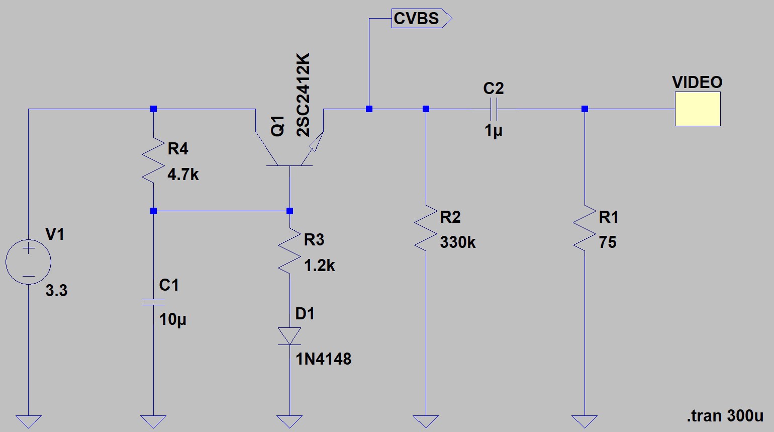
Using LTspice XVII I simulated the part of the circuit of the display module I didn't understand what its purpose was. For the composite video signal source, I used the NTSC voltage source published here by Bordodynov.

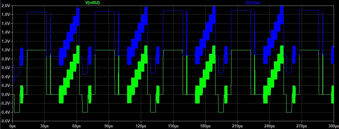
And here is the simulation results:

So it's look like this circuit is adding a small offset to the original signal, making it completely positive (no more signal falling under 0V). As I know nothing about video signal, I assume there is AC and DC coupling for video composite signal and that small module display works only with DC coupled signal?
To help me understand better, I looked for some litterature and found those:
- Analog - ADALM2000 Diodes and Diode Circuits (2e. AC Coupling and DC Restoration)
- maxim integrated - GET A GRIP ON CLAMPS, BIAS AND AC-COUPLED VIDEO SIGNALS
- Analog Devices - AN-1603 (Rev. 0) DC Restoration Circuit for an AC-Coupled Video Driver
- maxim integrated - How to Level Shift Video Signals for DC-Coupled Video Amplifiers/Filters
- RENESAS - AN1700 Video Driving Techniques for Mobile Devices
- LINEAR TECHNOLOGY - AN57 Video Circuit Collection
From what I understood, the composite video signal coming out of the mainboard should be AC coupled and that small circuit in the display module does a DC restoration before feeding the composite signal to the LC749880T (Image controller LSI for LCD-TV).
 Florian
Discussions
Become a Hackaday.io Member
Create an account to leave a comment. Already have an account? Log In.