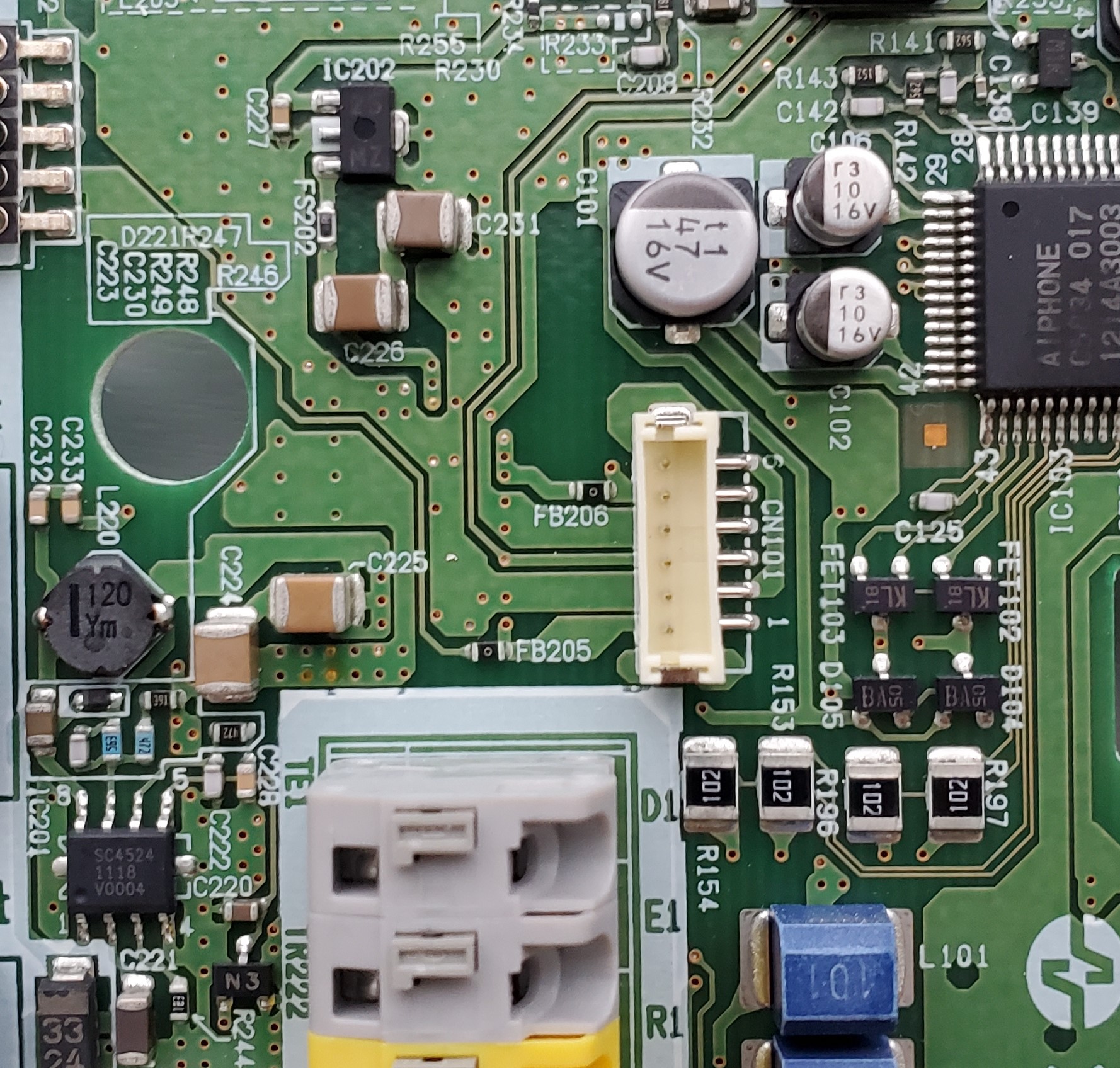
To confirm the power voltage of the display module and so the power generated by the step-down DC-DC regulator (LM2736YMK), I plugged the intercom to main power and did some measurements with my multimeter. I mainly focus my attention on the area where the display module connects to the mainboard, which is the following:

Unfortunately, despite the intercom being energized and being responsive when the front botton "通話/終話" was pressed, there was absolutely no voltage whatsoever in this area of the board. I thought something was wrong with my multimeter so I poked at the transformer and it's surrounding: my multimeter was working well.
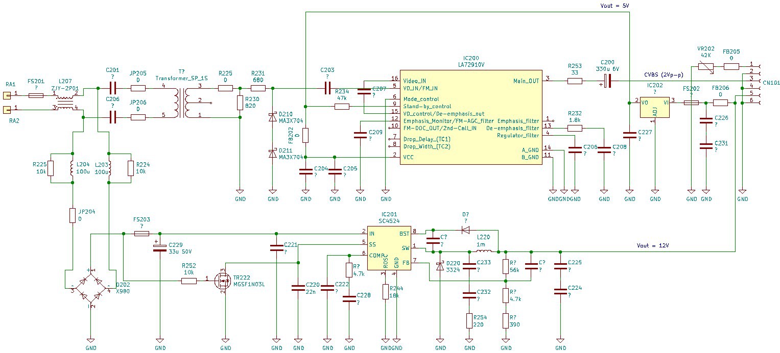
So after this infructuous result, I decided to reverse-engineer the traces going to this CN101 connector and damn that was a lot of work! But it was totally worth it as I managed to figure out:
- the mainboard provides 12V to the display module, which is generated from the video feed signal
- the LM2736YMK on the display module does generate 3.3V (calculated from the datasheet)
- the received video signal is FM modulated (demodulation IC is LA72910V from SANYO)
- pin 5 of CN101 on the display module is connected to the brightness control potentiometer of the mainboard
For more details, here is an image of the schematic I created but you can find the corresponding Kicad file in the FILES section.

My next course of action will be to simulate that circuit I didn't understand the purpose of and also see if I can connect that cheap 4.3" screen with double composite video input I bought quite a while ago. I hope it will be as easy as just connecting it to the mainboard video output to get it towork.
 Florian
Discussions
Become a Hackaday.io Member
Create an account to leave a comment. Already have an account? Log In.