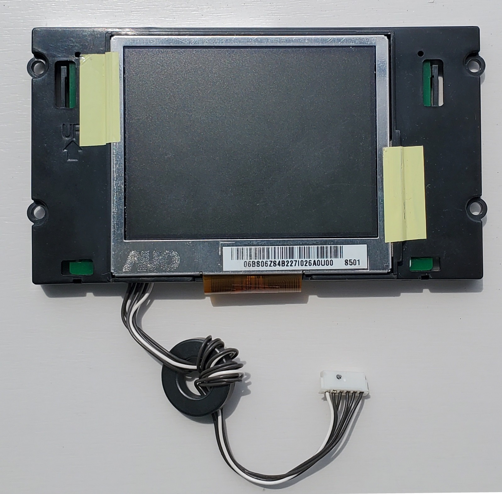
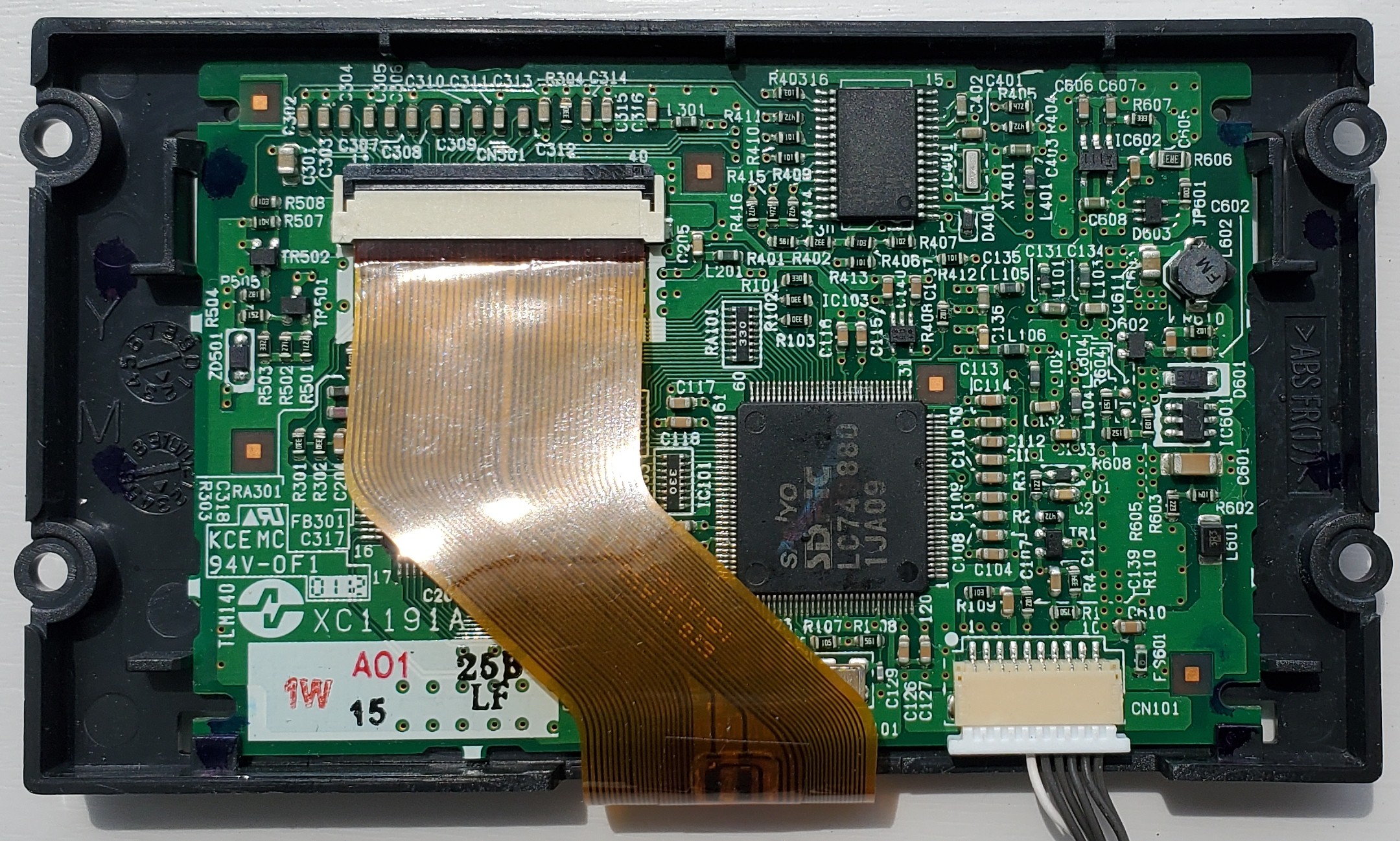
Let's see that display module in details:

it is labeled "TB10126 R" (frame top side), the TFT display itself is made my AUO and labeled "06B806Z84B227I026A0U00 8501". Those keyword returned nothing on Google so let's have a look on the back.

A 10 pin connector CN101, to which only 6 connections are made. Also, 3 big ICs (one is under the ribbon cable) which are:
- left to CN101 connector: SANYO LC749880T ➡ Image controller LSI for LCD-TV
- top one: 501S417 1146MK07 MYS ➡ unknown
- under the ribbon cable: XILINX XC9572XL ➡ High Performance CPLD
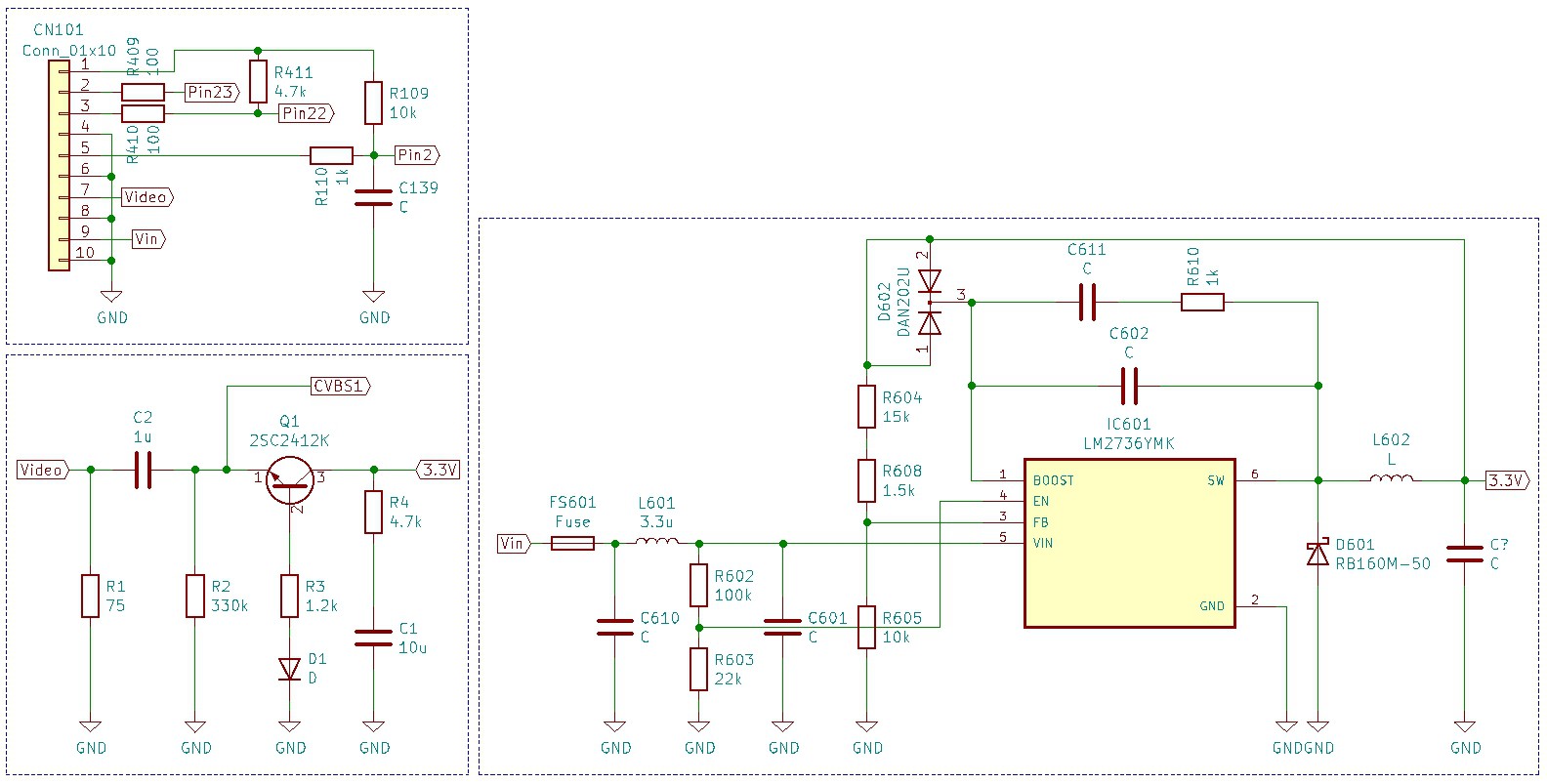
From the SANYO image controller datasheet, one of its feature is ”CVBS, S-Video,YCbCr/YPbPr input" and a closer look at the input table shows 2 CVBS inputs, one S-Video input and one YCbCr/YPbPr input. As this controller is right next to the only connector on this display module, I traced all the pins connection with a multimeter and came up with the following schematic:

To summarize:
- pin 4, 6, 8 and 10 are GND
- pin 9 is Vin (I assume 12V), which is step-down to 3.3V via a LM2736
- pin 7 is composite video input, which goes through a... I don't know circuit and then to CVBS1 of SANYO LC749880T
- pin 1, 2, 3 and 4 are unknown and are connected to respectively pin 2, 23, 22, 2 of the unknown IC
Next time I will confirm the input voltage of this display module, the ouput voltage of the LM2736, simulate the circuit between the composite video input and CVBS1 to understand its function and maybe analyze the intercom mainboard's circuit to which this display module connects.
 Florian
Discussions
Become a Hackaday.io Member
Create an account to leave a comment. Already have an account? Log In.