-
1How I soldered a PCB onto a breadboard
So I've been asked how I attached the breadboard to the PCB, the answer is that it was a pain in the ass.
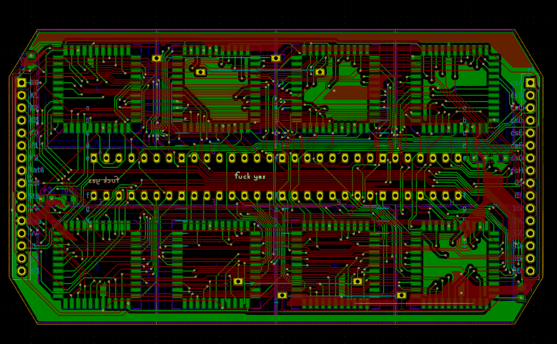
So in v0.1, I had those rows of plated through holes along the middle where I started by adding a blob of solder on each of those metal clips, then putting a fine tip on my soldering iron and sticking it through the hole from the other side to melt it and letting surface tension grab the PTH and bridge them together. It was a total hack that took forever and wasn't super reliable.
![]()
![]()
![]()
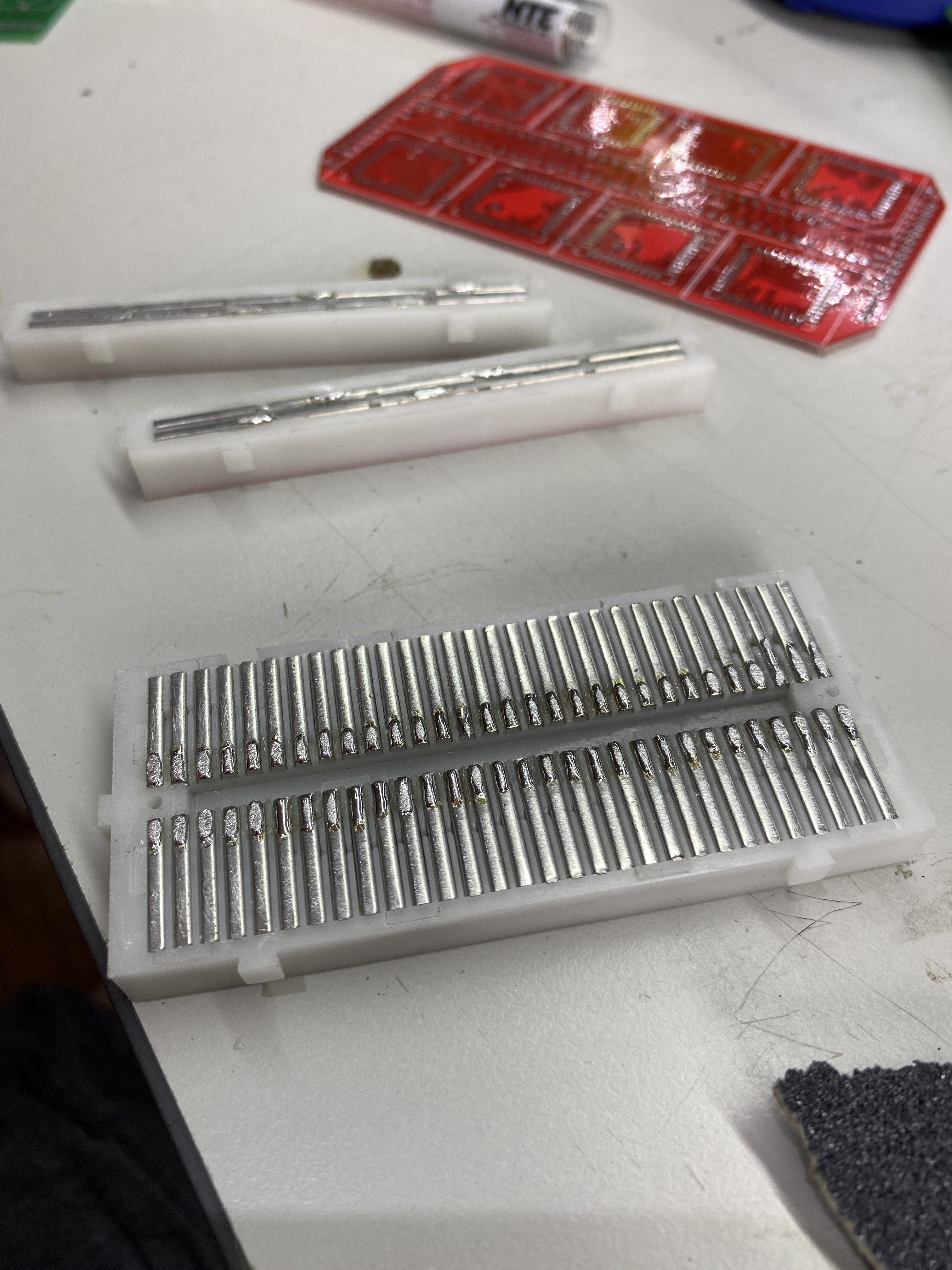
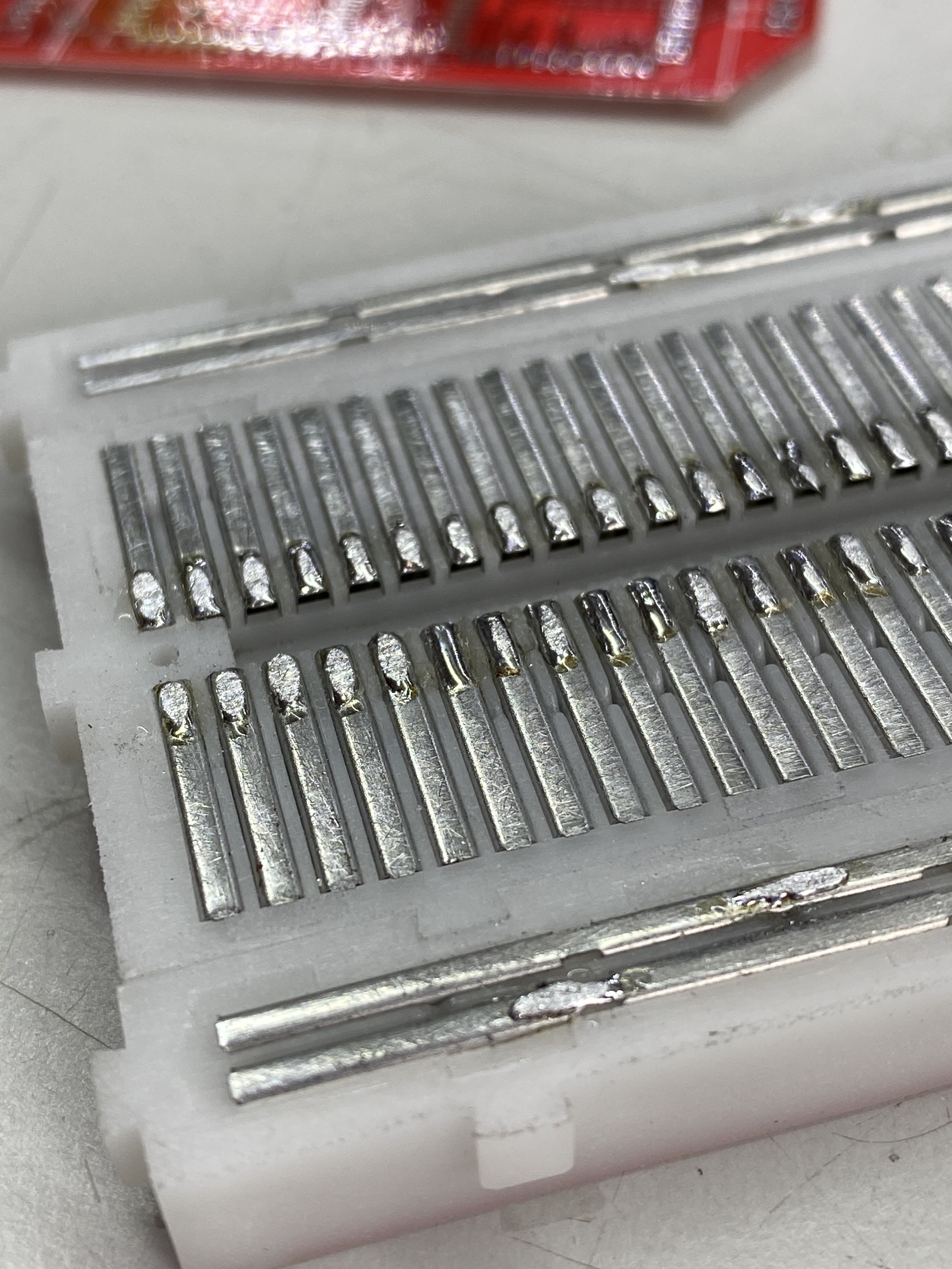
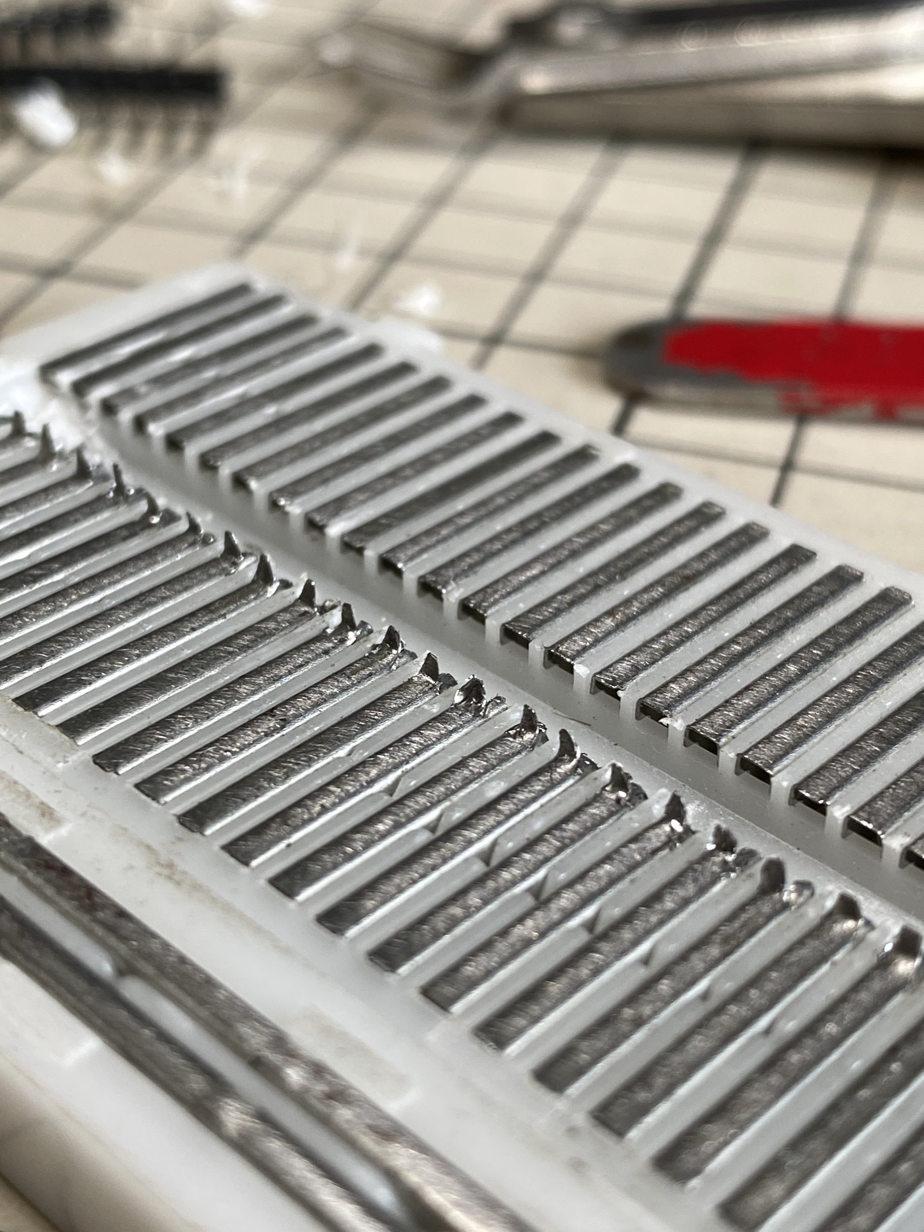
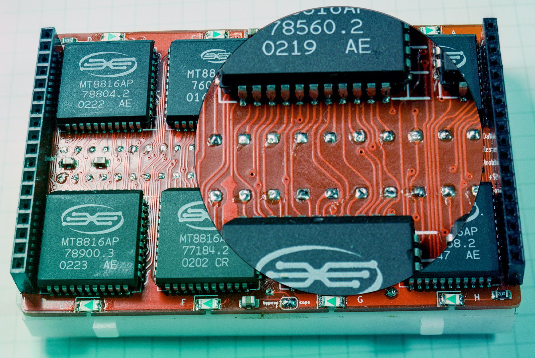
On v0.2, I made those middle rows closer together to roughly line up with the inner edges of those metal clips. I tried a few different things, drilling a hole in each one and sticking a wire through (I used that for the power rails), using 90° header pins to grab them from the side but the one that ended up working the best was pulling the metal clips out of the plastic breadboard and cutting a tiny tab into the inner side of each clip, bending them 90° and using that as a pin to solder into the holes. The pins only go like halfway through so from the back they just look like flat pads of solder, but it seems to be enough. In the pictures I've only done one side.
![]()
![]()
![]()
![]()
I should have taken more pictures of this process but getting those tabs to all line up perfectly straight and all fit at the same time was pretty finicky, and I never think to take photos when I really have to concentrate. It's weird because that means the easy parts are the best documented, and the parts people might have trouble following have almost none (you can see that effect in my code too, the function findPath() is ridiculously complicated and has 0 comments, sorry everyone)
 Kevin Santo Cappuccio



Discussions
Become a Hackaday.io Member
Create an account to leave a comment. Already have an account? Log In.