Kevin Santo Cappuccio
-
New Project Page!
05/23/2023 at 20:53 • 0 commentsIf you want to see future updates for this project, the new project page for Jumperless is here: https://hackaday.io/project/191238-jumperless
It's fundamentally changed enough that it's basically a new thing.
-
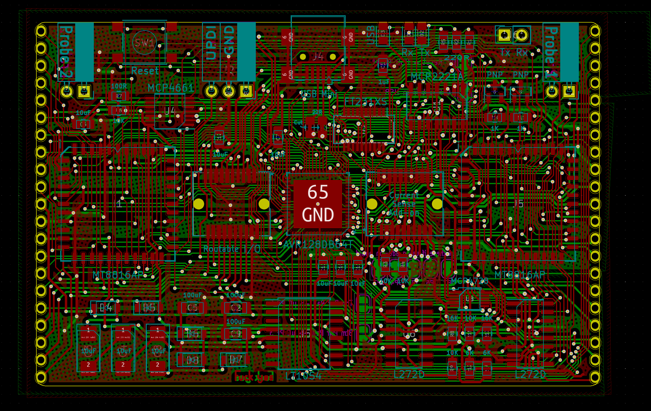
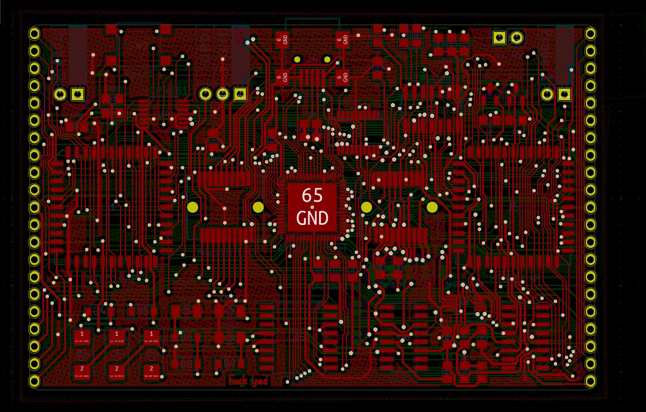
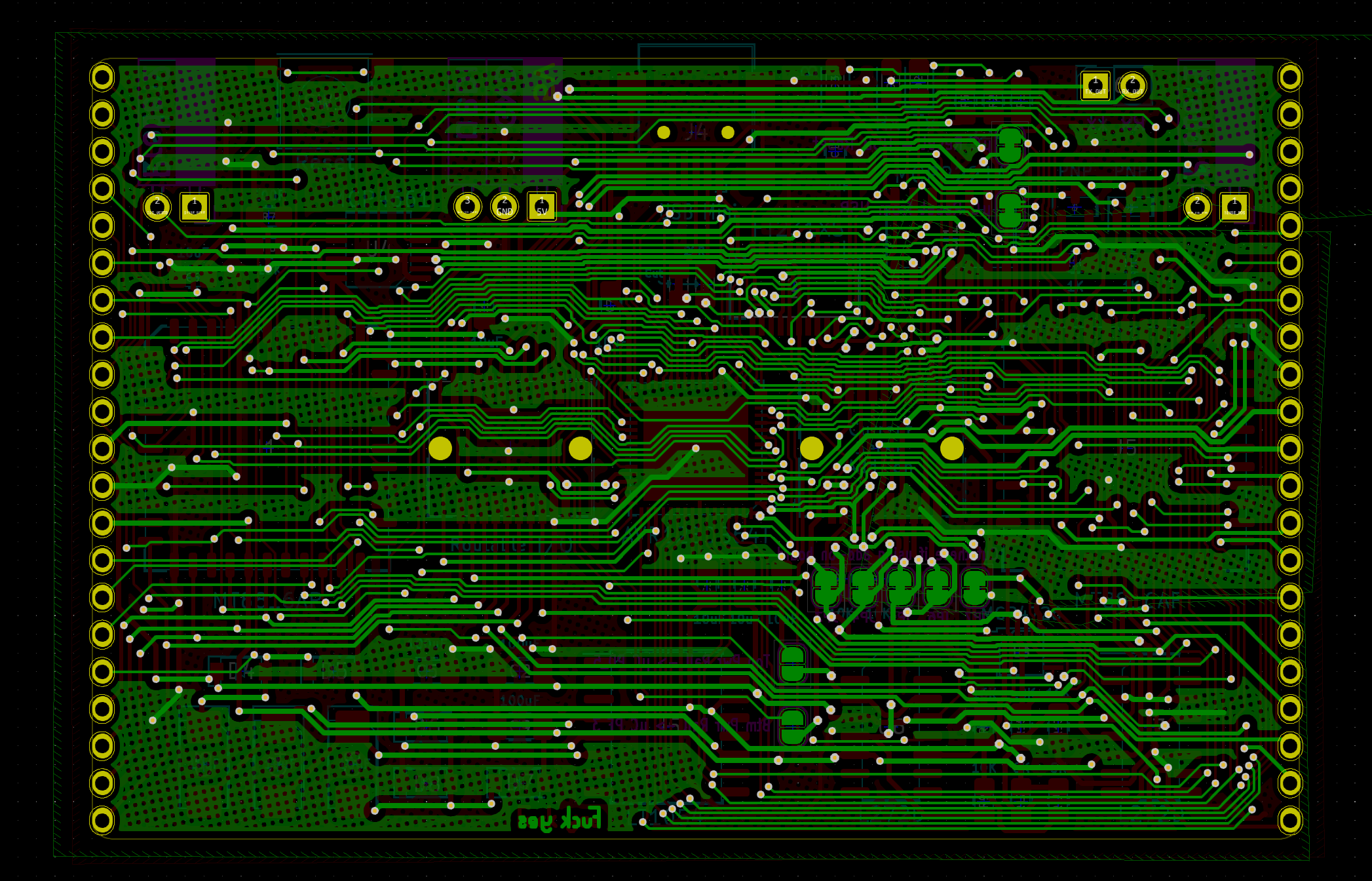
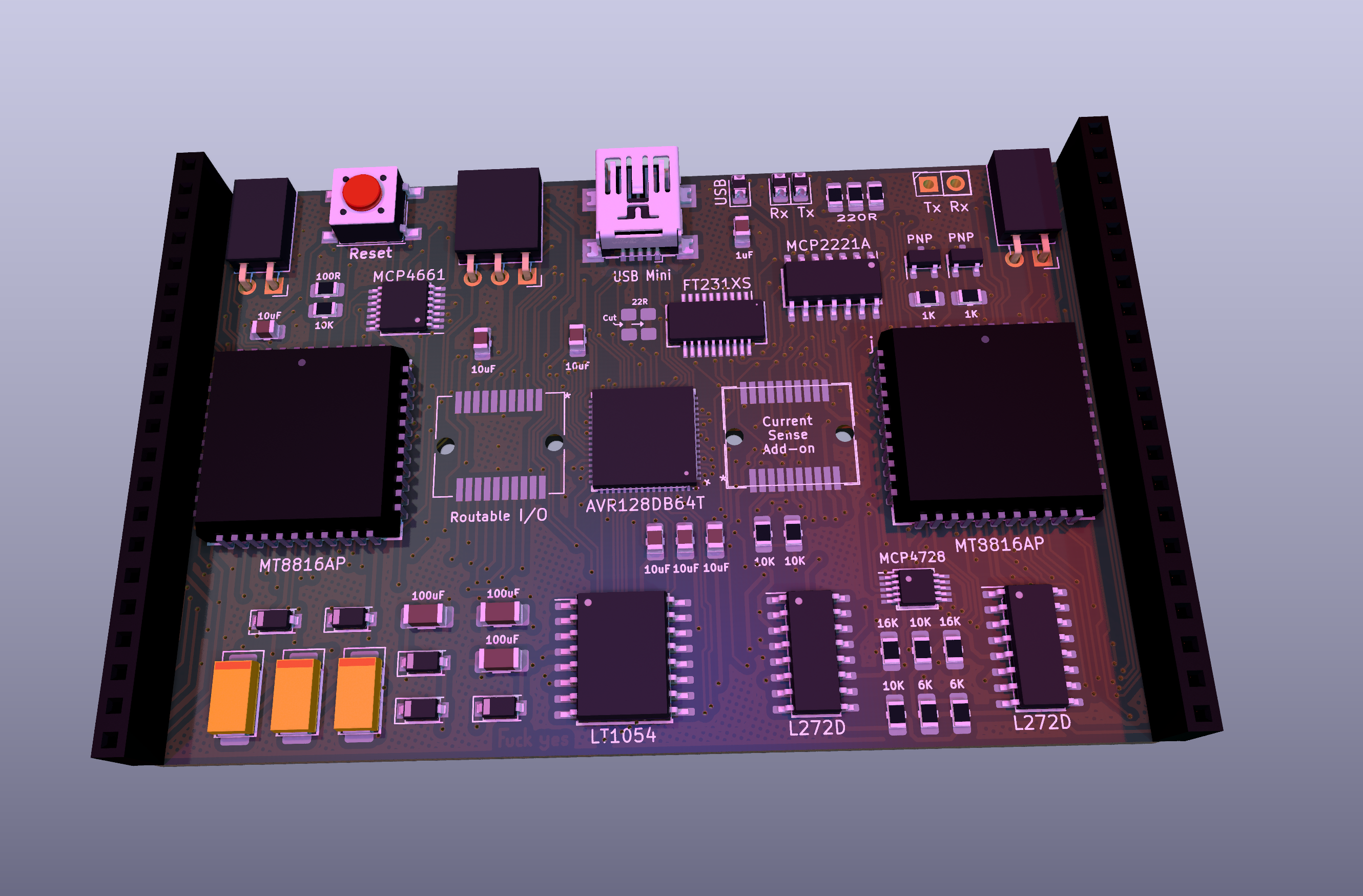
Control board routed!
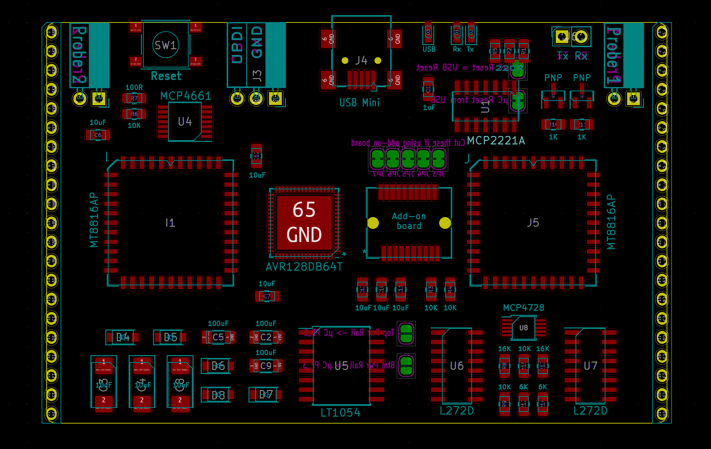
07/21/2022 at 16:52 • 1 commentPhew, that was definitely the densest board I've routed. I was really close to simply running out of room and having to make it a 4 layer board and start over.
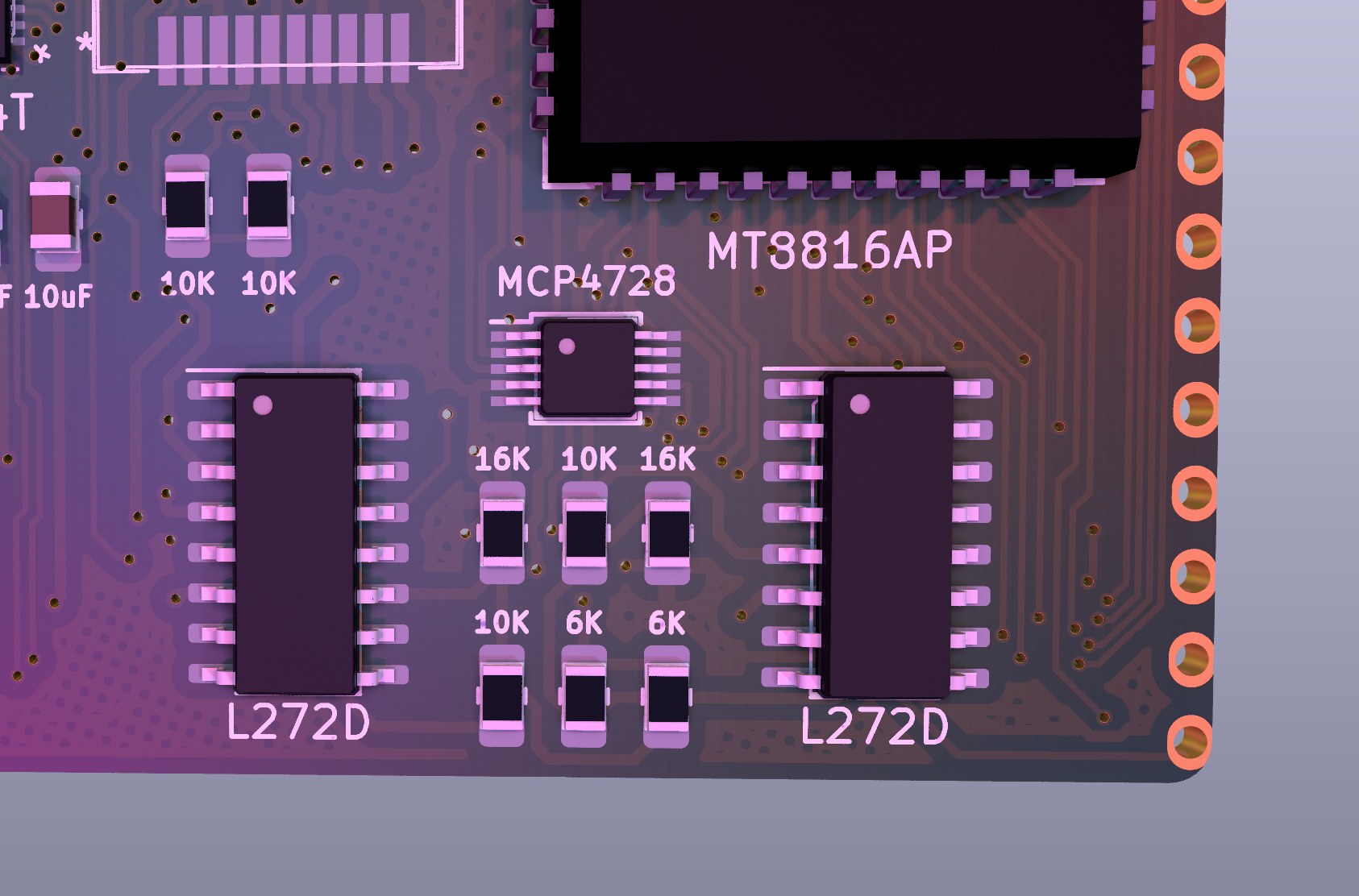
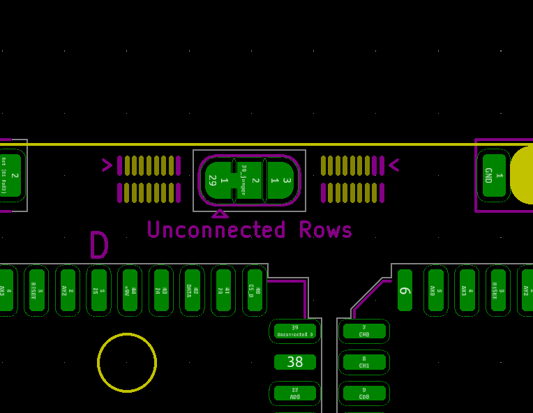
![]() And here it is after removing one of the D's
And here it is after removing one of the D's![]()
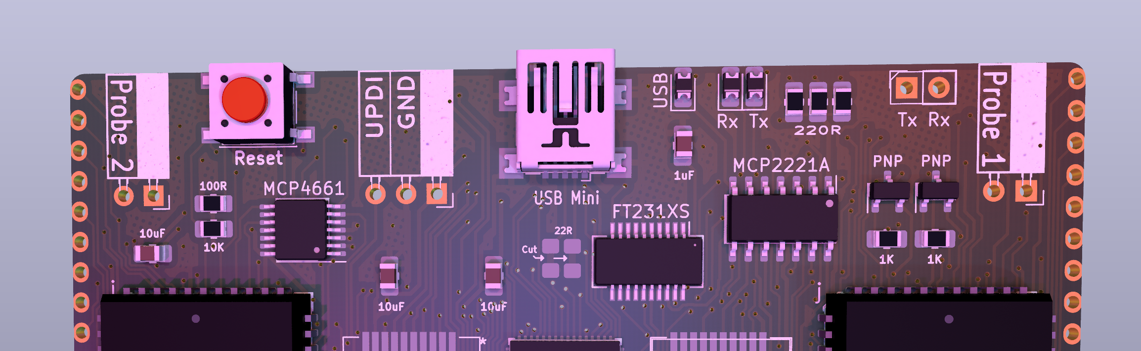
So I was talking to [Stephan Bourgeois] who is working on his really cool MicroMaster Mini (seriously, take a second to look at that firmware, it's ridiculously good and I'm super jealous) and he thought it would be nice to be able to plug it in to breadWare and get the much higher performance protocol analysis and injection stuff you'd get from a dedicated piece of purpose-built hardware. So I threw in another 20-pin card-edge connector that allows them to both speak UART to each other and route signals anywhere so we can eventually add support for that.
![]()
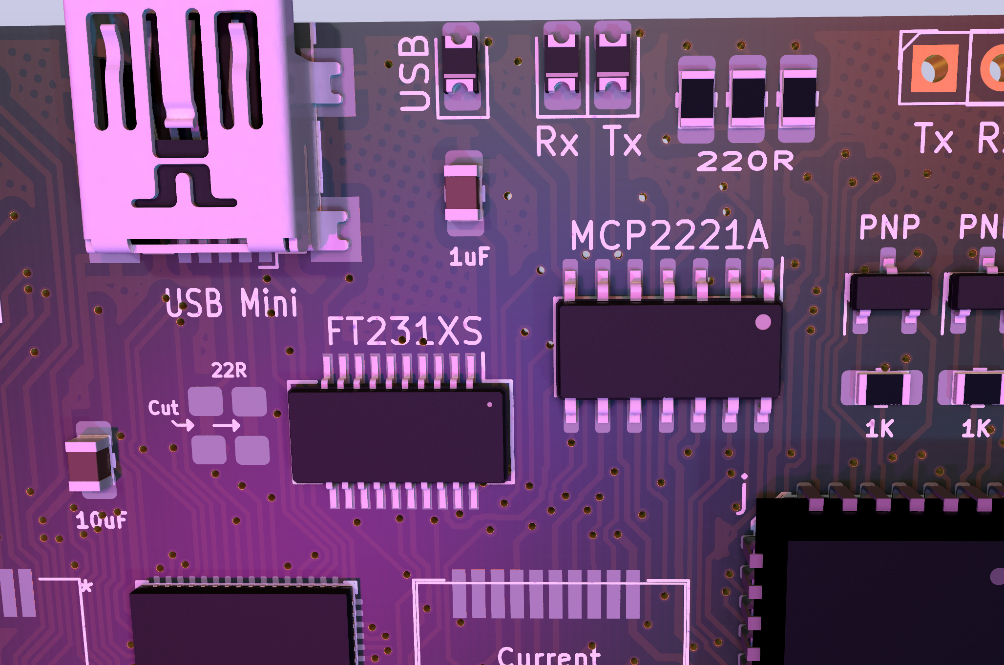
Also, I had forgotten about the chip shortage for a while until I was buying parts for this, and it turns out the MCP2221A UART-USB bridge might be impossible to get, so I added a footprint for the FTDI FT231XS just in case. The FT231X apparently wants resistors on the data lines while the MCP2221A doesn't, so I made a resistor footprint with bridged pads so we can have the option depending on which one gets populated. So hopefully I'm now half as likely to get screwed over by chip availability.
![]()
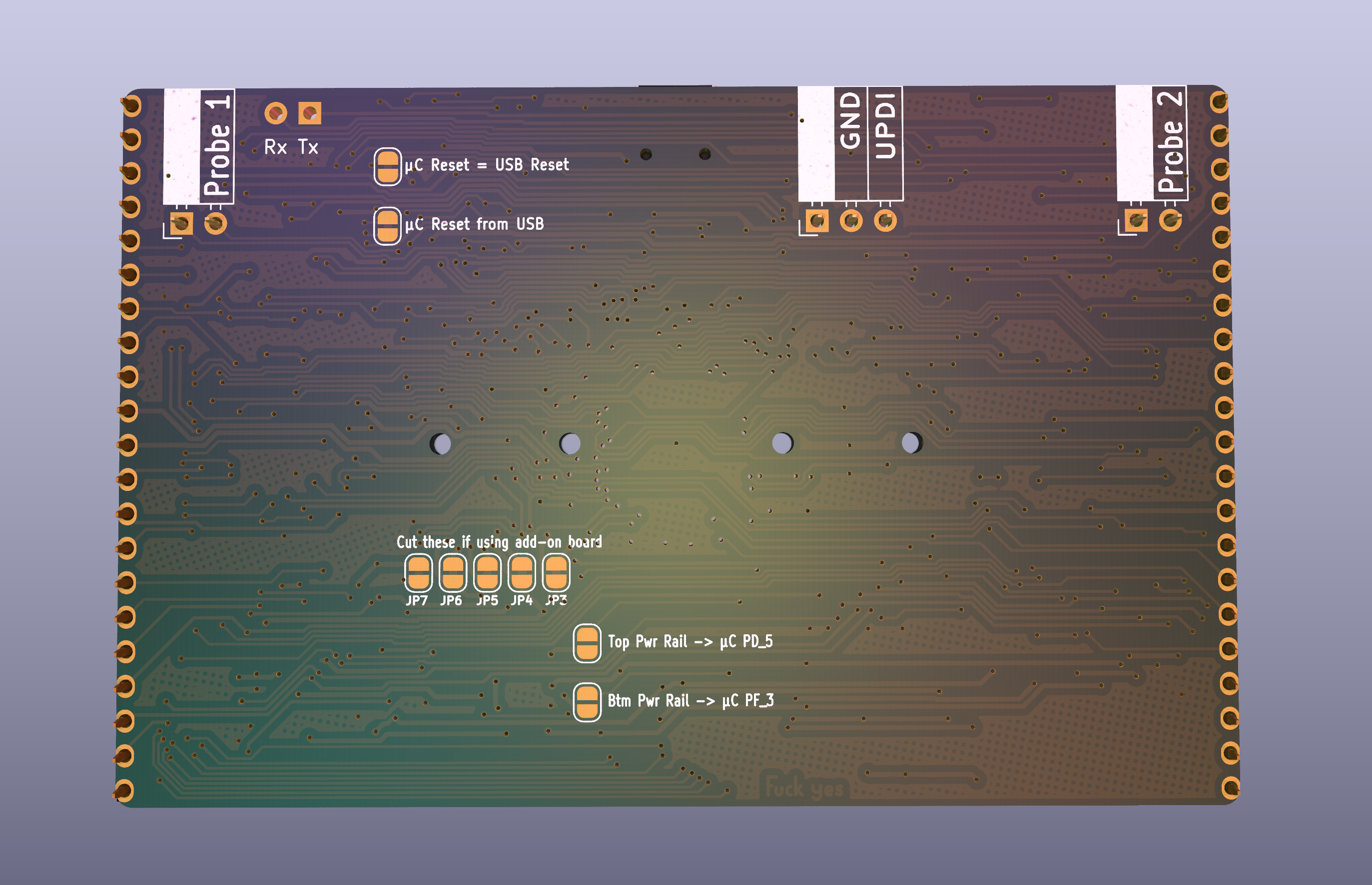
This thing should just come with an xacto knife for how many solder jumpers there are.
![]()
Chip availability might also be a problem for the MCP4728 and MCP4661 but I decided I'm just going to hope for the best with those instead of covering the board in unpopulated footprints.
![]()
![]()
And it's not like I had a ton of extra room for that
![]()
![]()
But it's finished, now I just need to do the top board (which will definitely be 4-layers, so it should be a little easier if I can get my brain to intuitively switch between 4 layers without having to think about it.
-
Finally some progress on version 3!!!
07/10/2022 at 23:28 • 0 commentsSo it's been a while since I actually did anything on breadWare, but it's always been in the back of my mind and everything I've worked on since has been helpful in figuring out how I should approach this next revision.
![]()
I haven't routed any traces yet so it's easy to change things, so if any of you Hackaday people see anything wrong (or even if you think something could be better) I would love to hear your armchair engineering.
![]()
Here's a list of the things I changed from version 2:
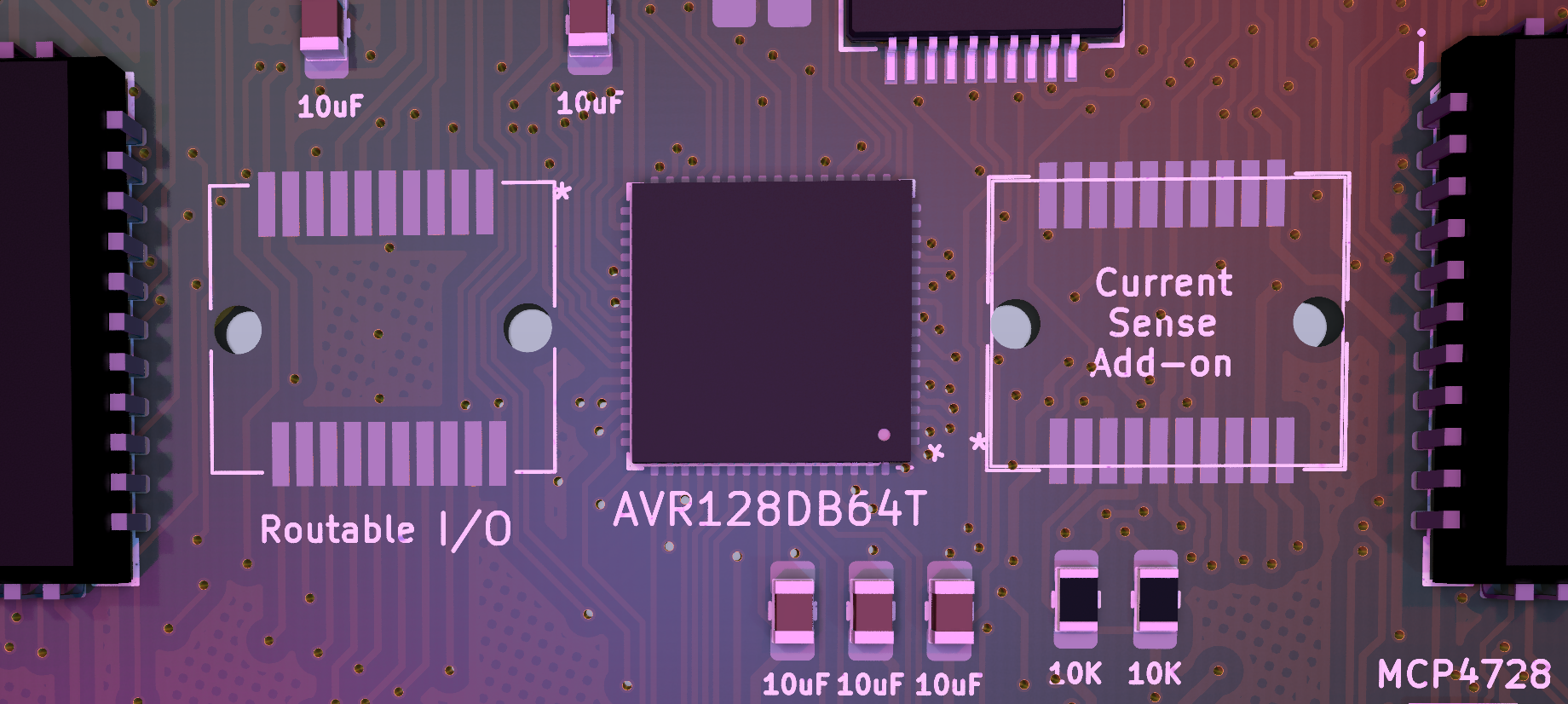
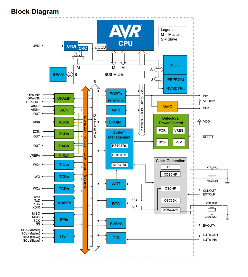
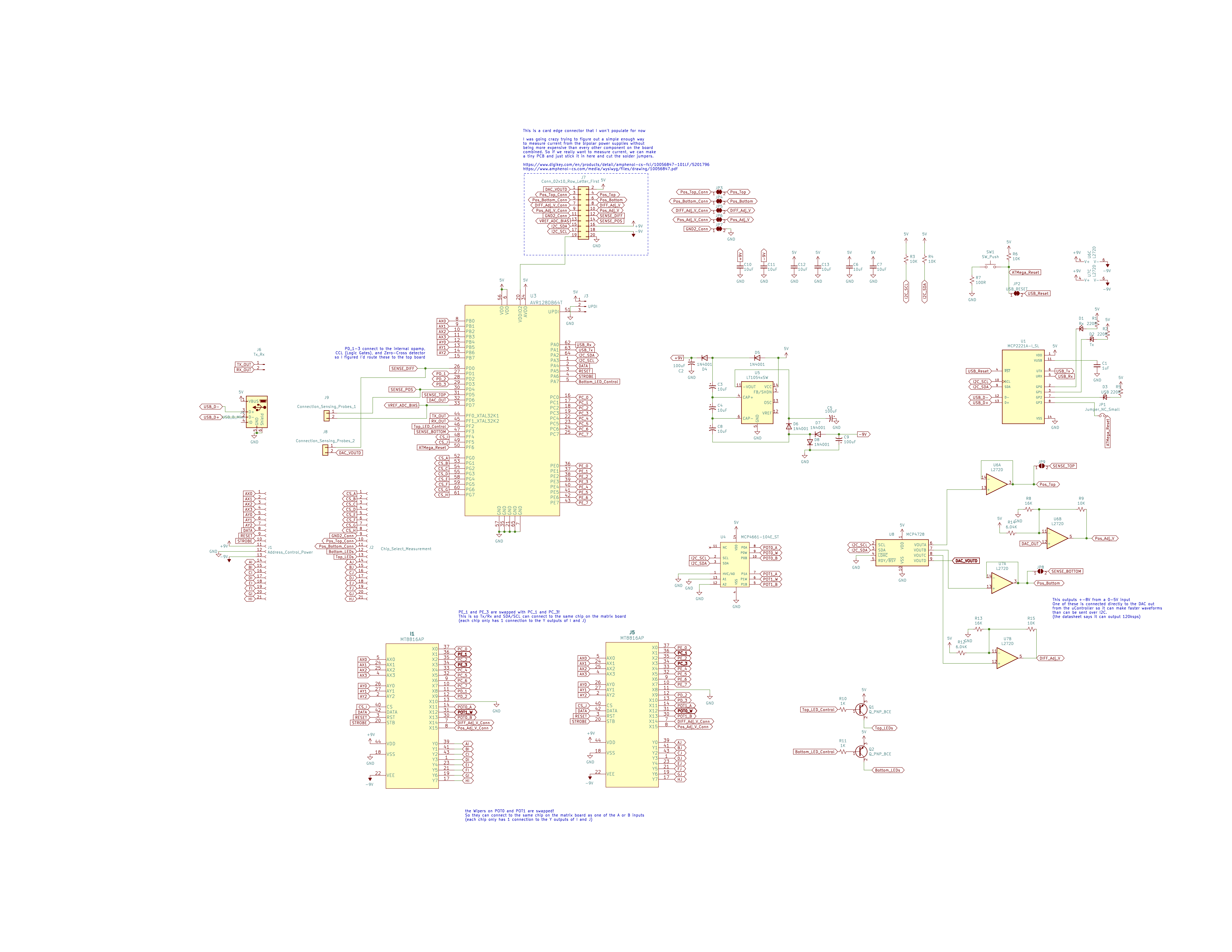
- I'm using an AVR128DB64 as the microcontroller instead of the ATMEGA "Every-tool-just-kinda-forgot-to-support-me" 4809. I've been way into these new series of chips Atmel has been coming out with. And having all the documentation from https://github.com/SpenceKonde/DxCore is super nice. [Spence Konde] and [MCUdude] deserve a frickin' Nobel Prize.
![]()
I managed to get a good deal of those peripherals on the left side connected to somewhere you can actually use them on the breadboard.
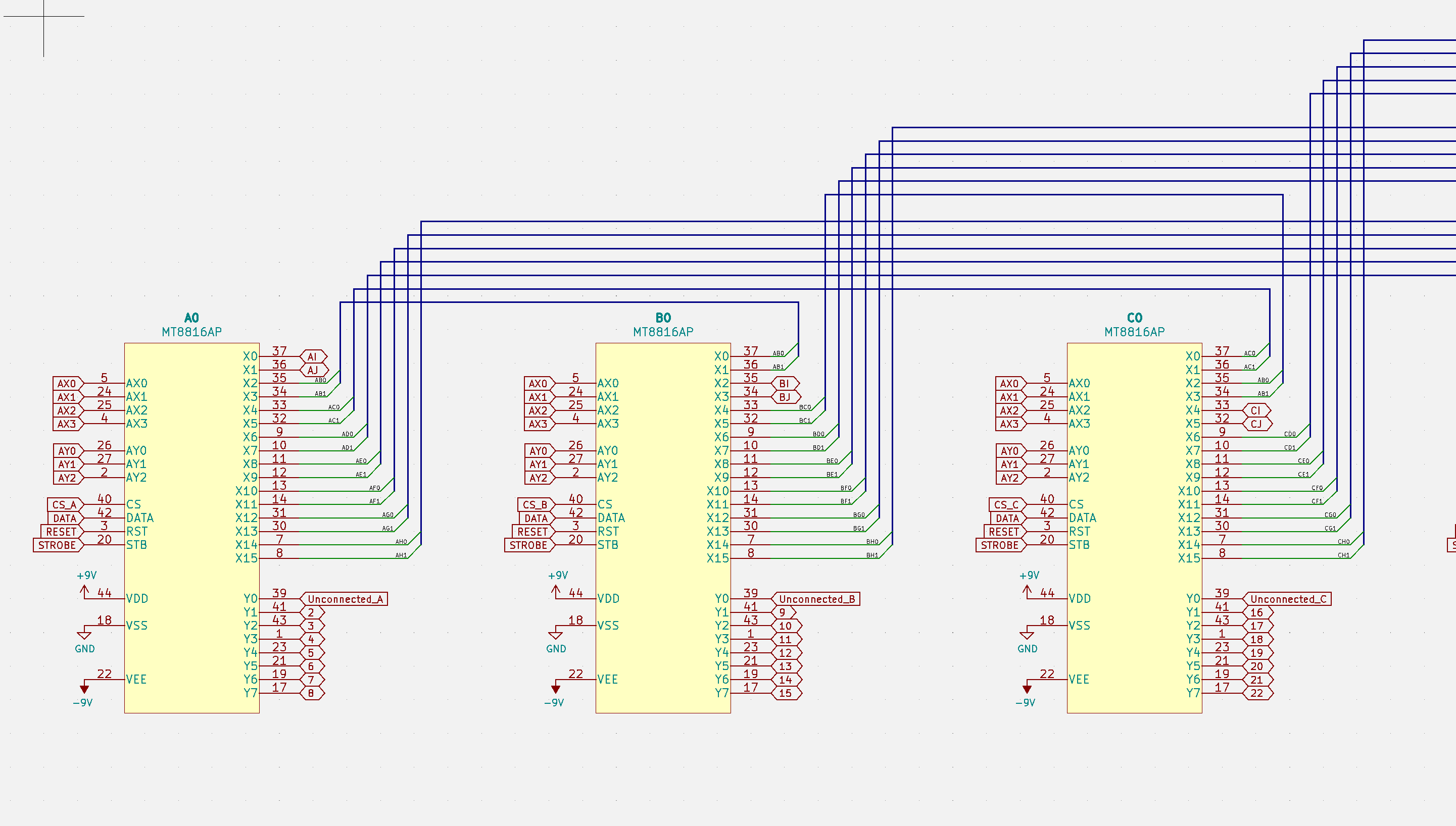
- Every crosspoint switch is connected to every other one on the board directly (but now there's only 2 direct connections between each chip) and the 2 extra connections are each connected to the 2 (instead of one) special function chips on the control board. I'm pretty sure this is a better way to do it than Version 2 but most of the problems come out when writing the code to handle the connections. So instead of spending too much time trying to guess every pitfall beforehand, I'm just going to try it and see where the new problems arise. (Once again, suggestions will be lovingly welcomed)
![]()
- Also every crosspoint (instead of only 4 of them) has an unconnected Y input because those were ridiculously useful to cover for times where there aren't enough direct connections or whatever. That also means there are 4 points on the breadboard that aren't connected to anything (which will probably be useful for sensitive/high voltage stuff) and their location is selectable with a solder jumper (corners or right side)
![]()
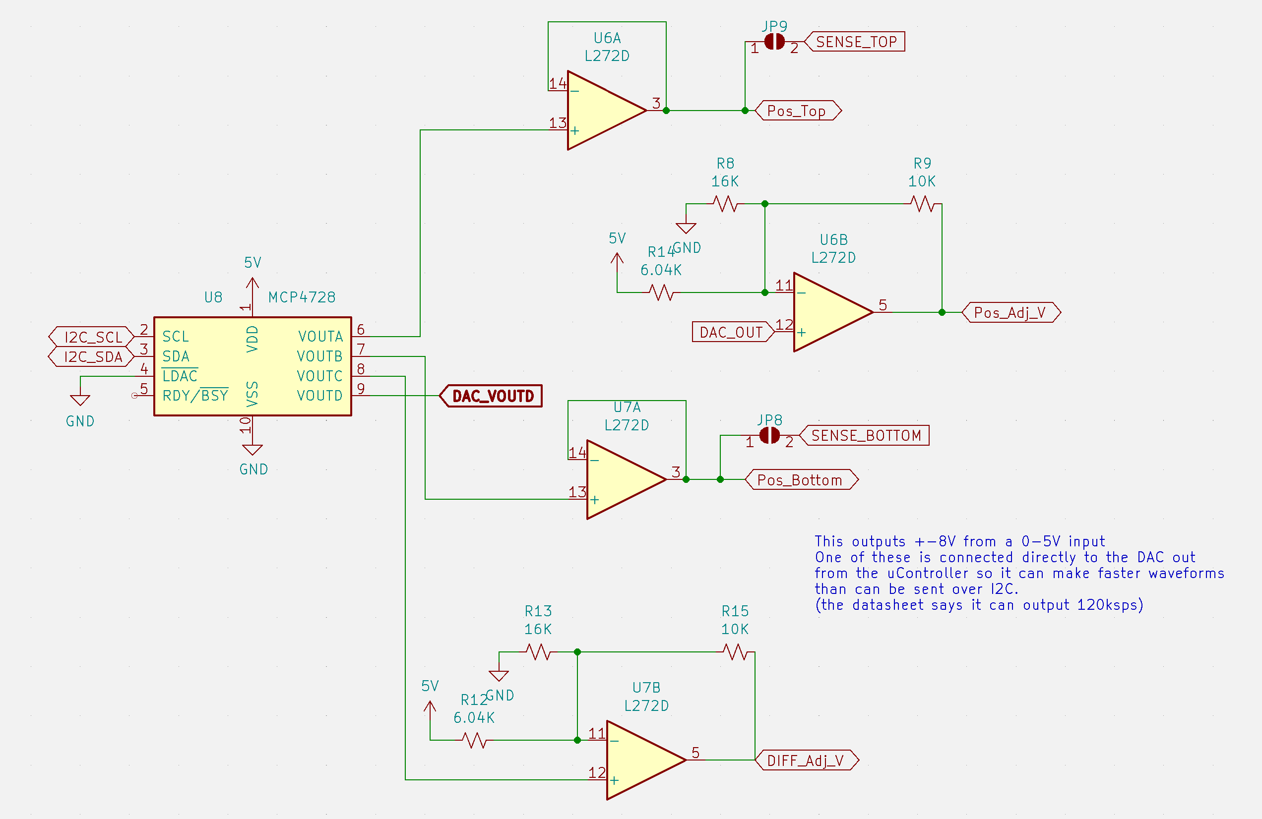
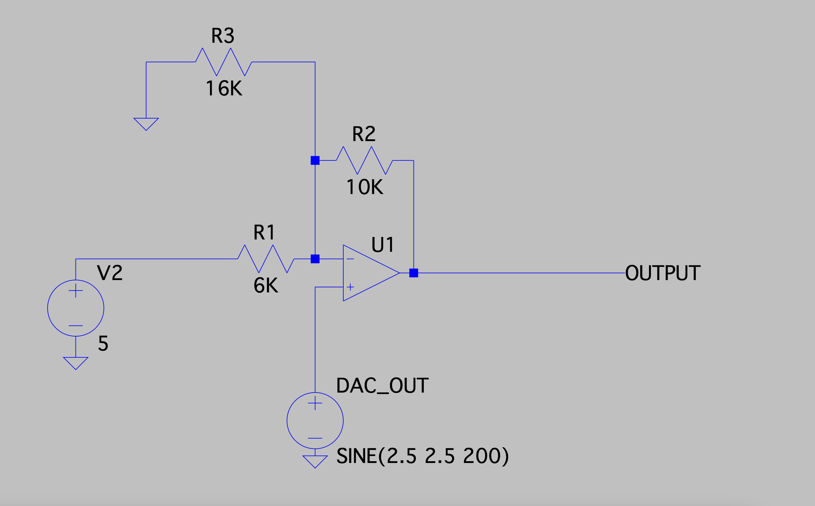
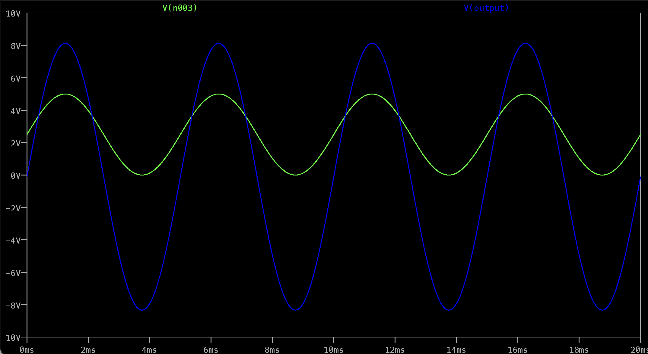
- I redid the power supplies a bit to get +-8V from the 0-5V DAC. And I also connected one of those directly to the AVR128DB64's built in DAC so I can use it as a function generator. The datasheet says it can output at 120Ksps, so if everything works basically like it does in LTSpice, it shouldn't be that bad of an arbitrary waveform generator for this purpose. (But if there's some analog ninja out there reading this, please let me know if this is going to blow up if my face.)
![]()
![]()
![]()
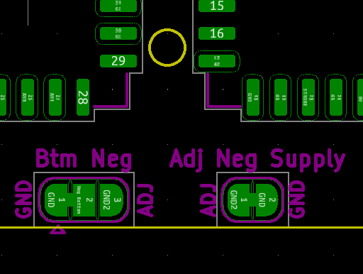
- The negative rails are directly connected to ground by default now because as I learned from the last version, switching grounds around with a ~65Ohm resistor in series sucks. And creating a "ground" by having a power opamp output 0V was a bad idea if you don't want it floating all over the place. But that can be changed to and adjustable voltage with yet another solder jumper. I went absolutely jumper crazy to avoid making any hard decisions.
![]()
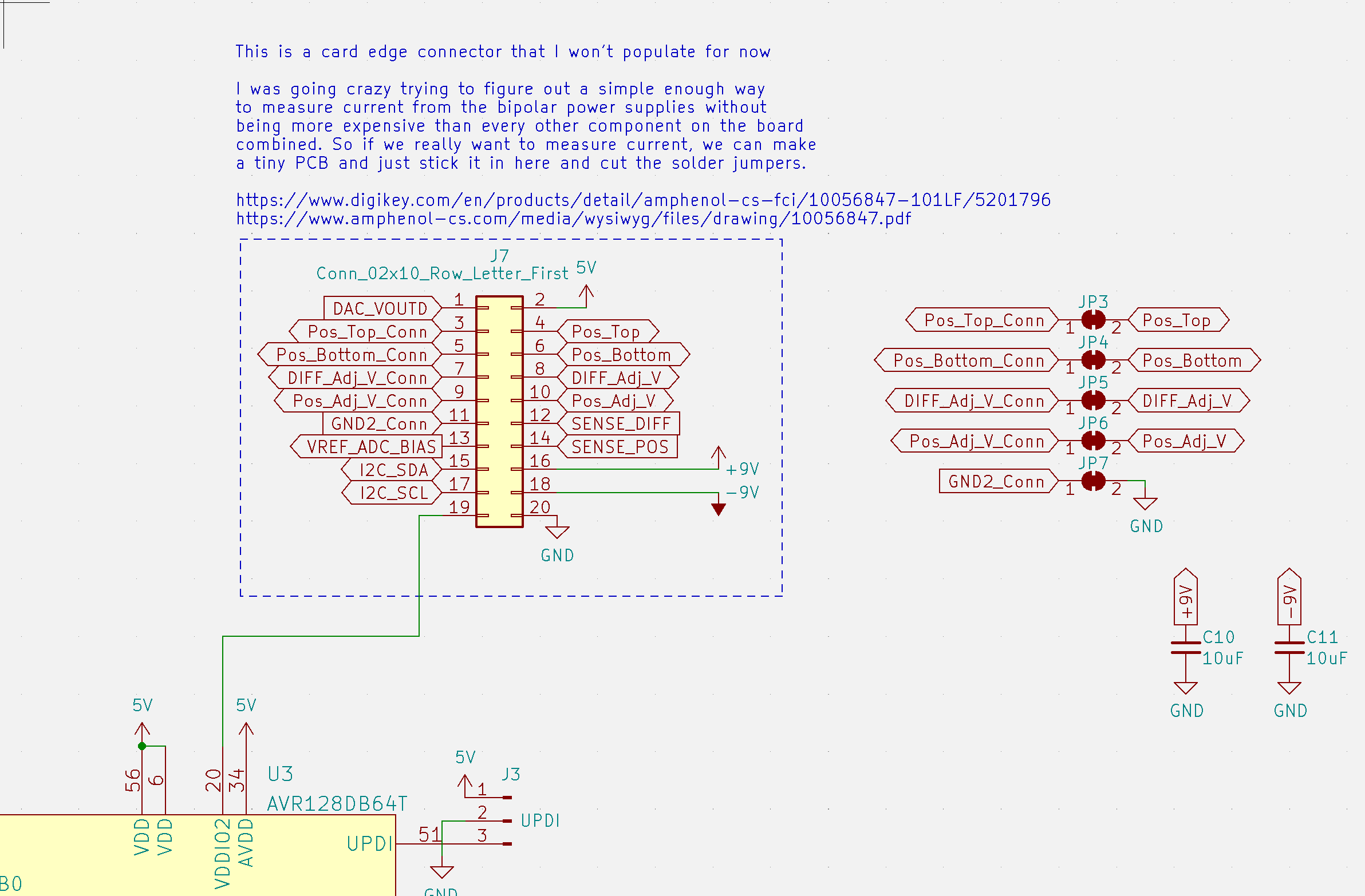
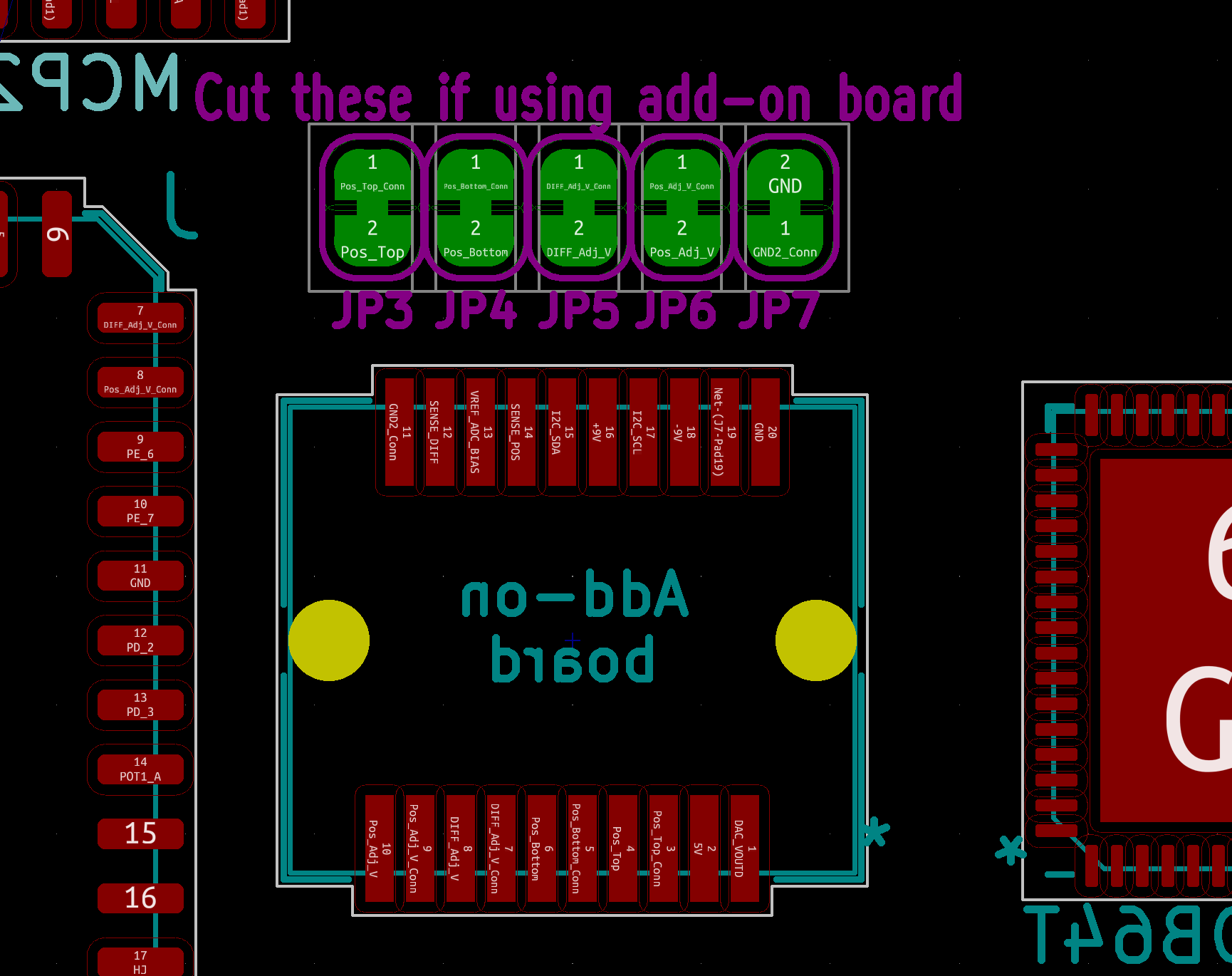
- Speaking of not making any decisions, I put an entire 20 pin card edge connector on the control board so if we ever decide to add current measurement (or anything else) we can populate it and throw in a little PCB to do that.
![]()
I spent about a week trying to figure out a way to measure current from the power supplies that was simple and cheap enough to be worthwhile. There's definitely some way to do this without adding a ton of parts or one really expensive chip, but I figured I'd leave that up to future us to deal with and just route every signal we might need to a connector.
![]()
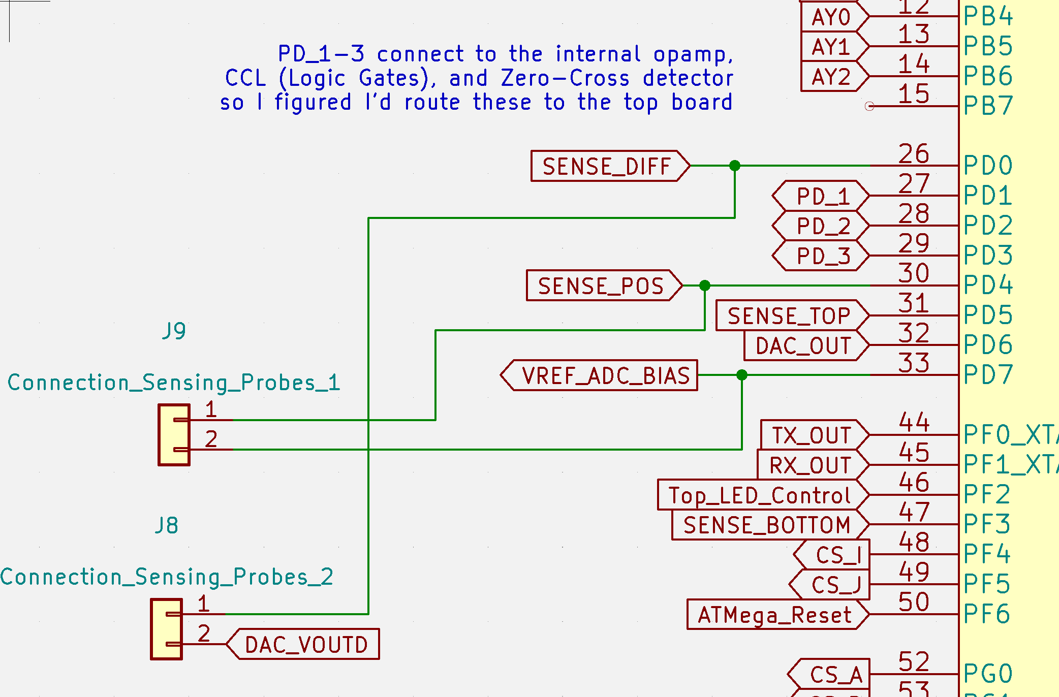
- I also added 4 probe outputs so you can just plug in a few jumpers and make connections by poking 2 points like I originally wanted to do for version 2. Probe 1 connects to the inputs to one of the AVR128DB's internal op amps, so there's a bunch of other things you'll eventually be able to use these probes for.
![]()
![]()
![]()
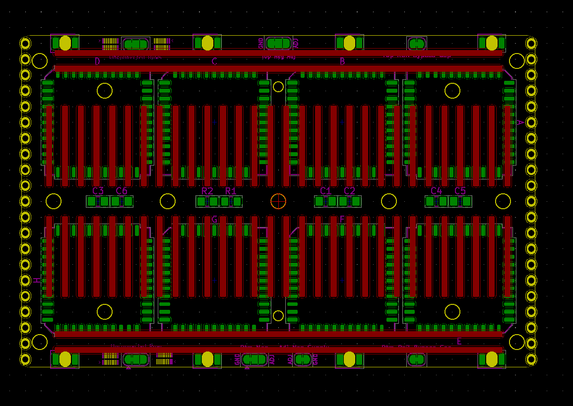
- The top board is now has holes to that line up with the holes on the back of a Jameco Valuepro breadboard so instead of painstakingly soldering the breadboard on with tiny holes drilled into the metal clamps, I can use Z Tape and to make the connections and use the screws to provide enough pressure to make that work. Or if I'm really lucky, I can use solder paste and hopefully melt it before the plastic melts too. But that seems unlikely. This is going to be a 4 layer board so I don't have to try to route around that breadboard footprint. (I'll post this KiCad footprint somewhere in case someone wants to use this approach for something else.)
![]()
Notice the clearances for those corner holes is so tight I had to rotate those chips to give me that tiny bit from the filleted corners. Hopefully I'm paying attention when I put these together.
![]()
I can tell already the firmware for this is going to be a nightmare, so it will probably be worthwhile to actually map out how everything's going to work together instead of just running in and writing code all willy-nilly like I usually do.
![]()
![]()
-
breadWare: The Movie
11/08/2021 at 11:49 • 0 commentsHere's my explainer video for breadWare
I hope it adds a little more clarity to what this thing does. Some (~40%) of the features I mentioned in the video haven't been coded yet. But we've been banging out a lot of code lately to make a majority of the things you see in this video real demos and not just lies.
-
Why not an FPGA?
06/22/2021 at 02:30 • 0 commentsI've received this question a lot, so instead of answering it in random comment threads I'll just do it here. I'm referring to research I did a year ago and didn't bother to look anything up for this to get any hard numbers. Take the things I say here with a grain of salt, because to be honest I'm not particularly learned in the ways of the FPGA. But I did learn enough to know that I don't need to learn any more about them for this project (one day I will have a project that actually needs one and isn't just crammed in for no reason, and I'm looking forward to it)
I considered something like this early on, but it turns out FPGAs won't work well for this particular use case. But on a super high level, breadWare is sort of an FPAA (Field Programmable Analog Array) built out of a bunch of discrete chips to make it work the way I had originally imagined they would.
Here are some fun facts about FPGAs (that weren't so fun when I learned them because it meant the design was going to be waayy more complicated):
-Although we think of them as routing signals through a bunch of logic gates, how they actually work is by sending the signals through LookUp Tables, so it basically simulates a logic gate by just reading places in memory that you've programmed with a bitstream. The LUTs are connected by a crossbar switch internally, but they know exactly how it's going to be used so they can simplify out a lot of the things that would make it "general-purpose." From what I understand, the input signals always go through a large set of LUTs (which is fine in a purely digital world, because they can just map 1 to 1 and 0 to 0 ) before they can go through the crossbar switch. So it's more like a Star Trek teleporter where it just scans and reassembles you on the other side.
-Nowadays it's really rare to find FPGAs with inputs that are even 5V tolerant, most are only like 2.8V tolerant, so you'd either need to be super careful with the connections or have 60 separate level shifters.
-You need analog signals to make even the simplest of digital circuits work, for example a 555 timer needs to read the voltage on a capacitor to generate a clock signal.
-I got really excited when I heard about FPAAs, but turns out they're basically unobtanium for less than $100 per chip, and they're usually only a few analog blocks thrown into a regular FPGA. Apparently JPL made a chip in-house for spacecraft, but I can't imagine a regular person could buy one.
So now I have a microcontroller and a digital potentiometer do those extra things, and the ATmega4809 I'm using does have a built-in hardware logic gate they call a "Configurable Custom Logic" cell, as well as a ton of other fun things to mess around with.
But yeah, an FPGA version could probably do some awesome things that this one can't.
-
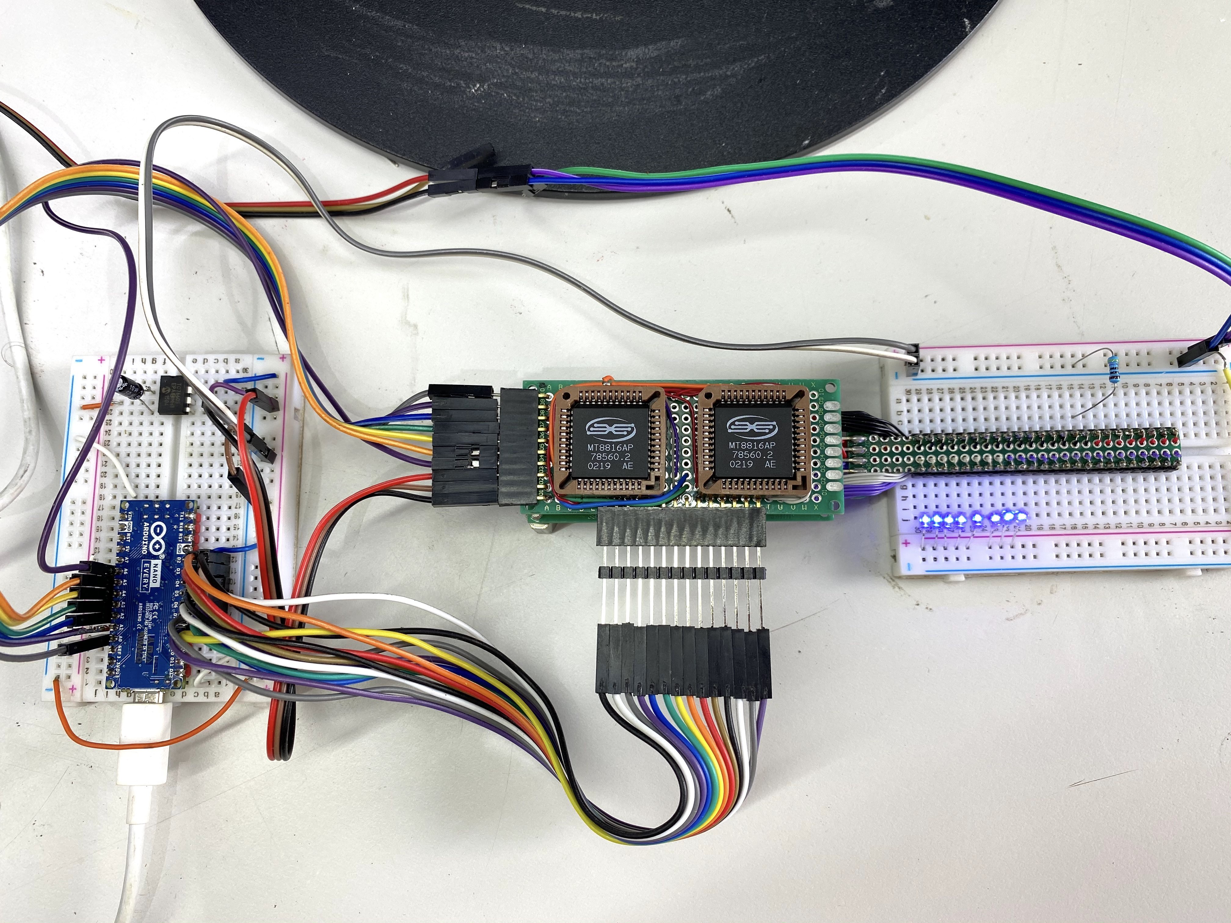
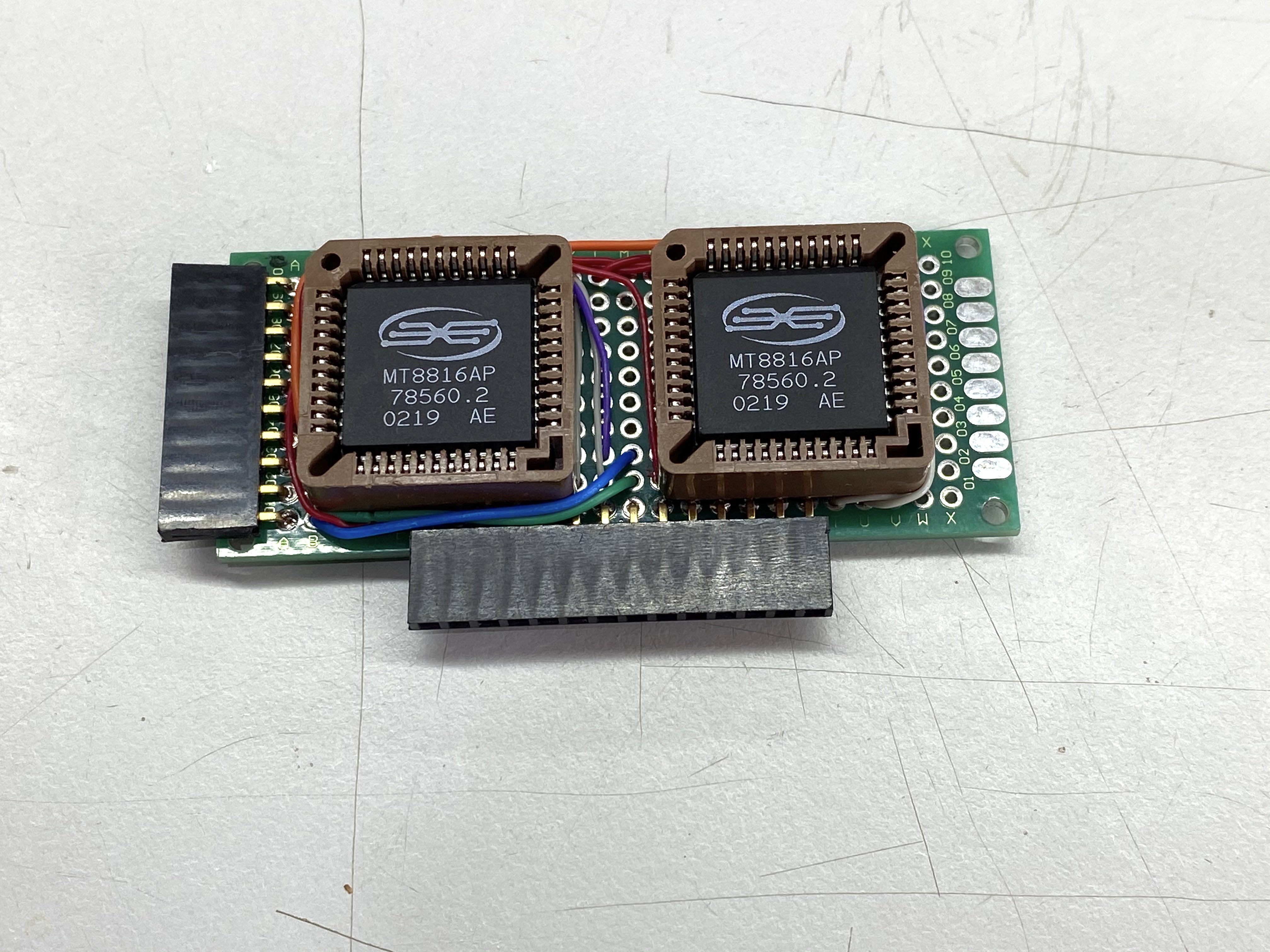
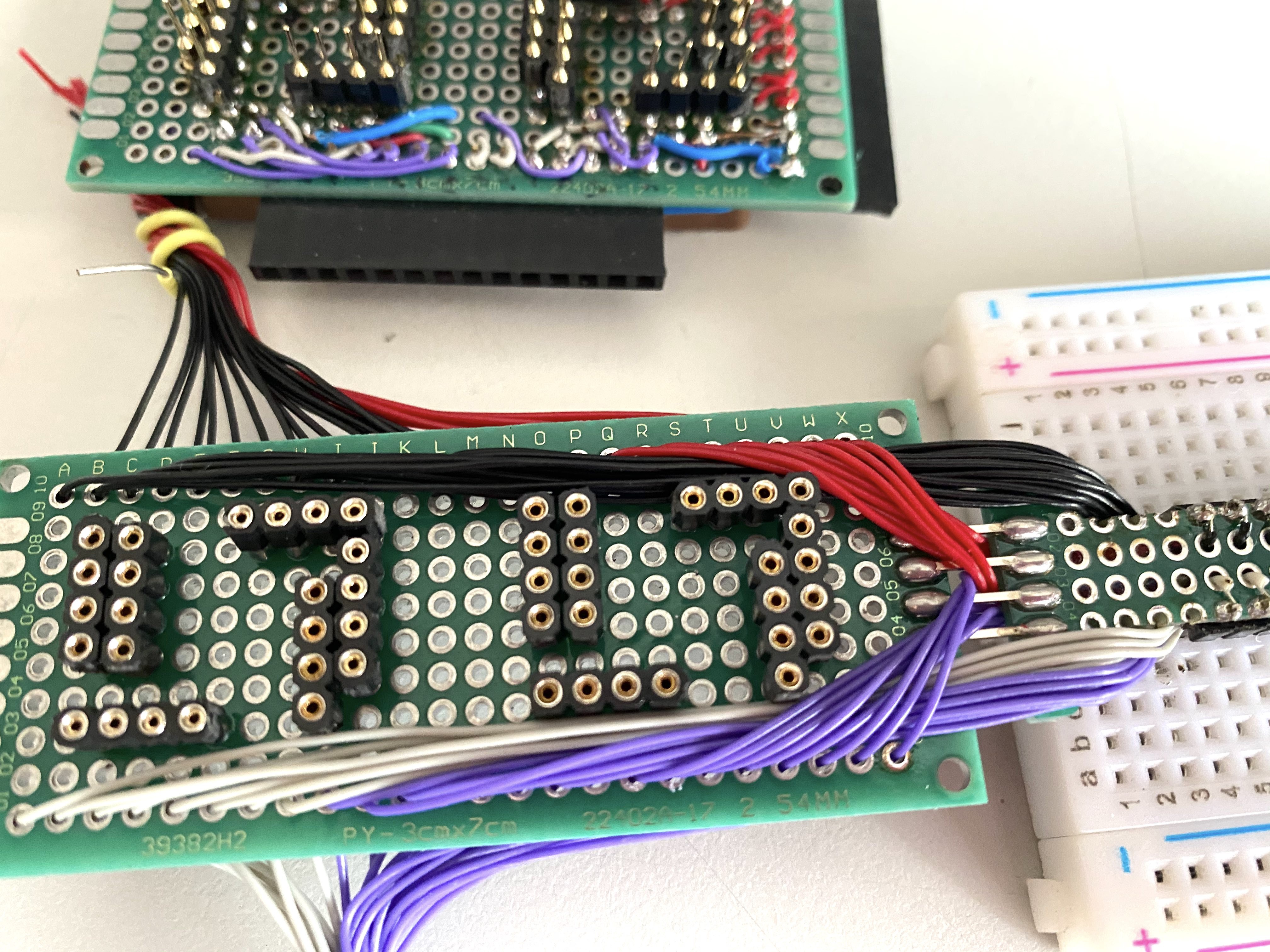
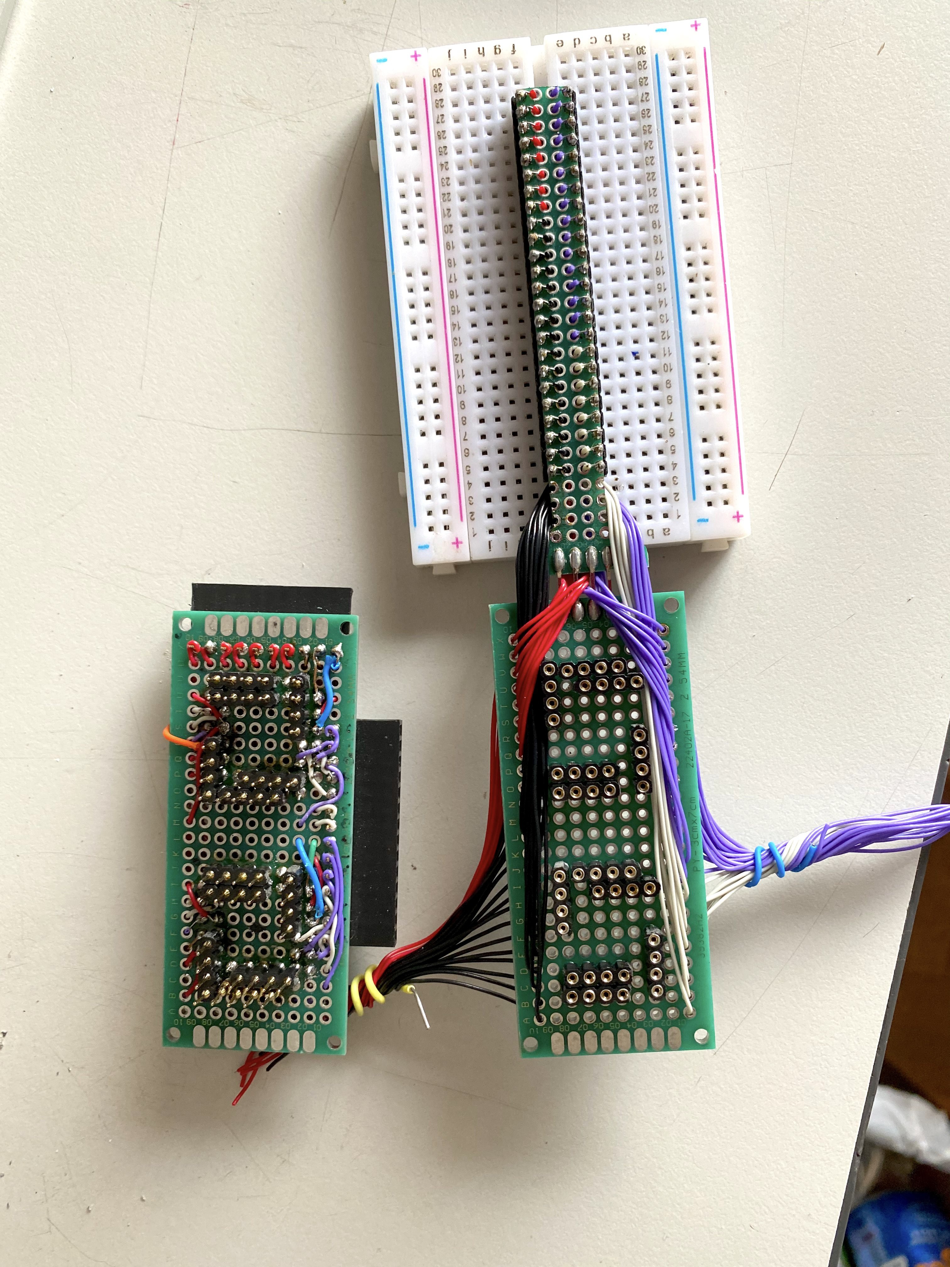
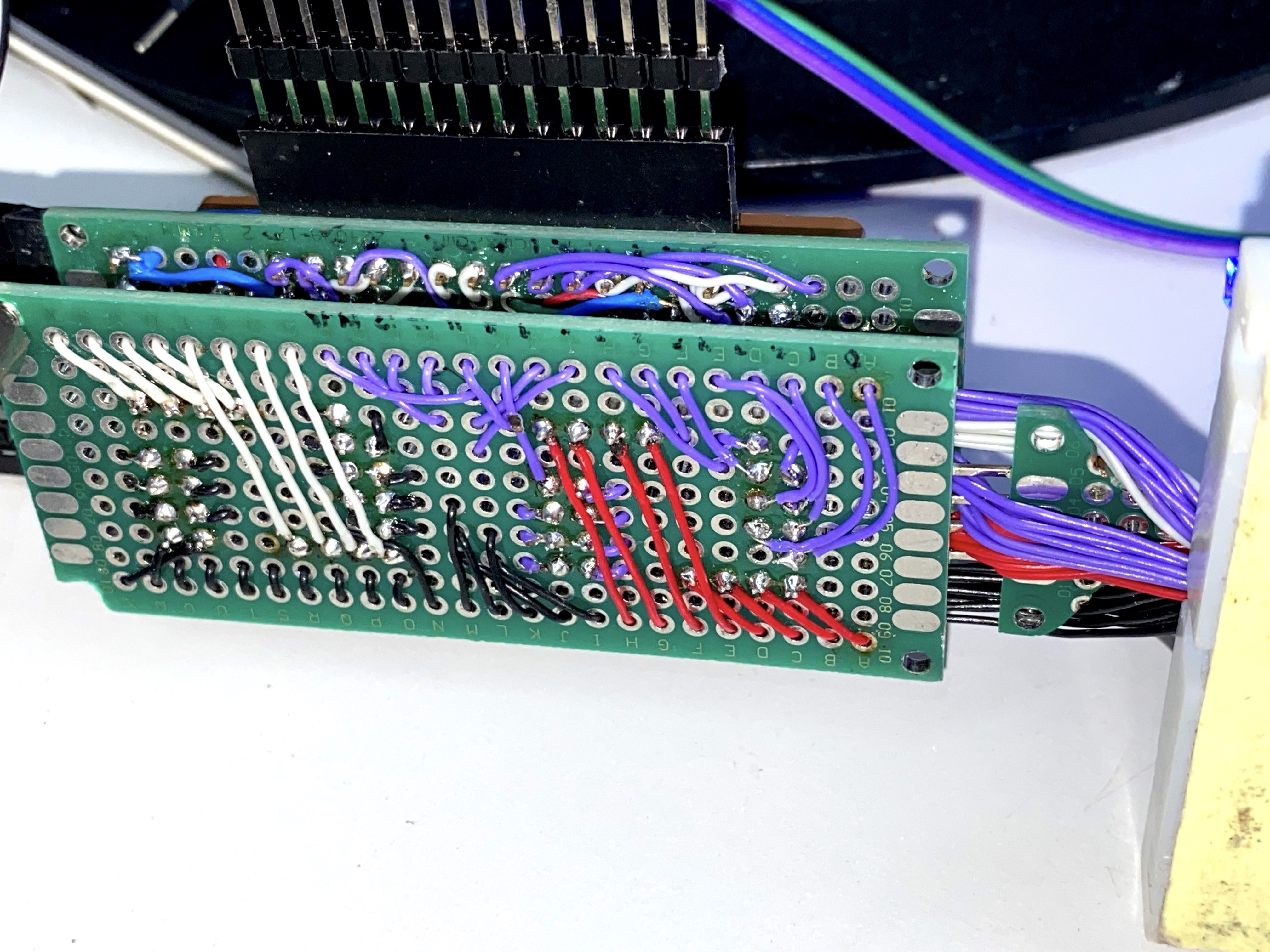
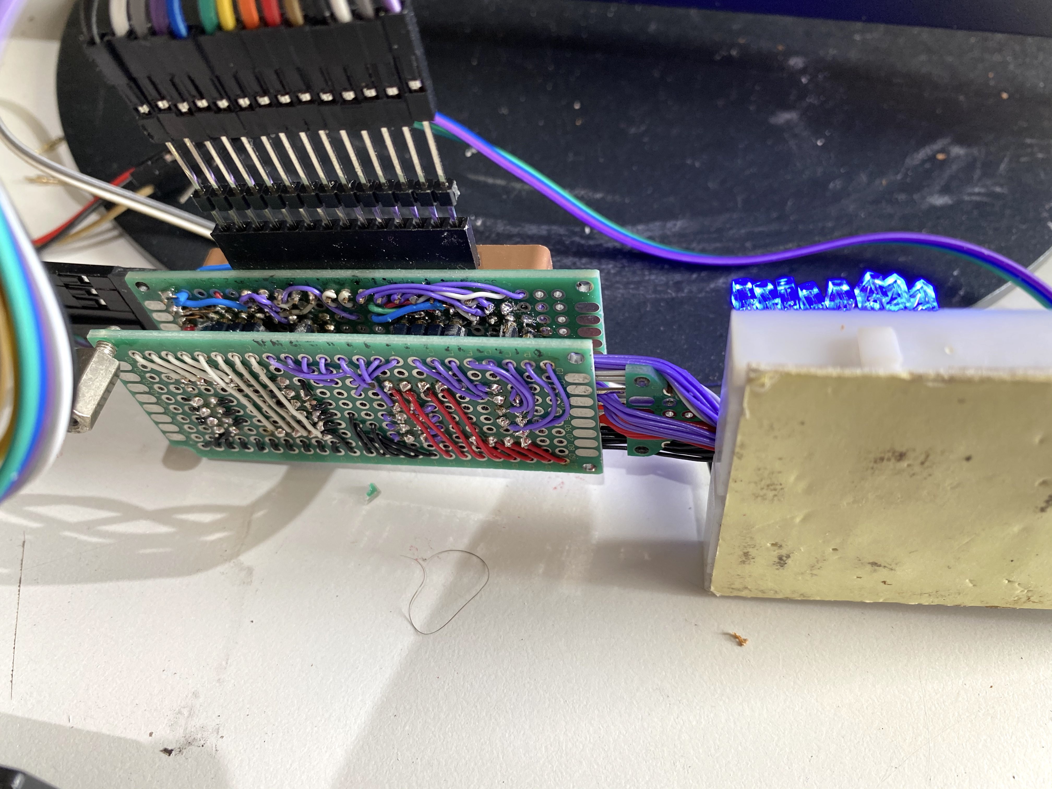
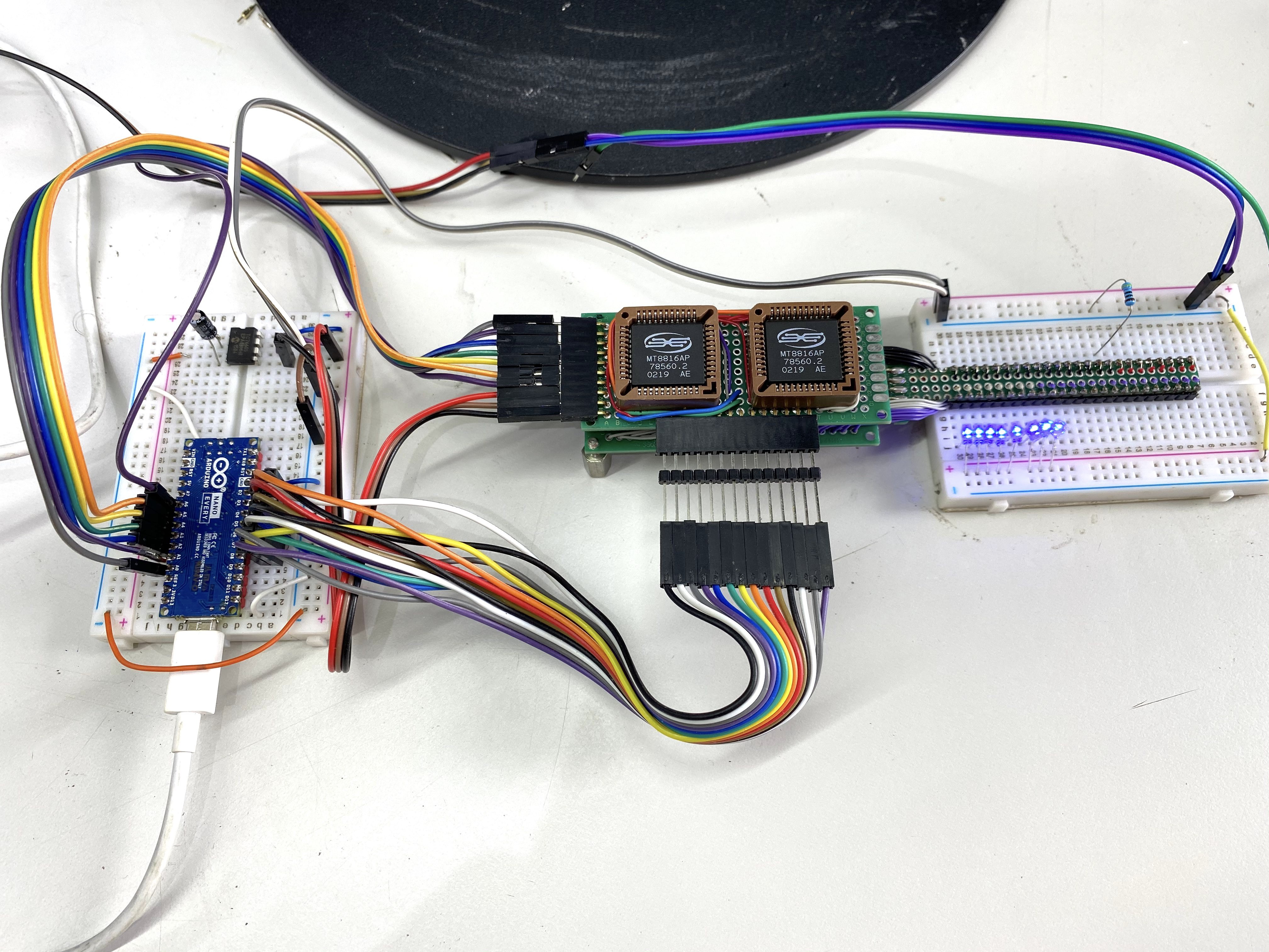
Dual Matrix Test
06/16/2021 at 12:18 • 0 commentsAfter seeing that a single MT8816 would work, I wanted to make sure you could route a connection through 2 of them and still have a reasonably good connection. Because using a single 32x32 crosspoint wasn't gonna happen, I think they actually might exist (it's been a while since I looked into it), but they're in the few hundred dollar range per chip, and they're generally for HDMI switching so they don't really have the qualities you'd want in a general purpose analog switch.
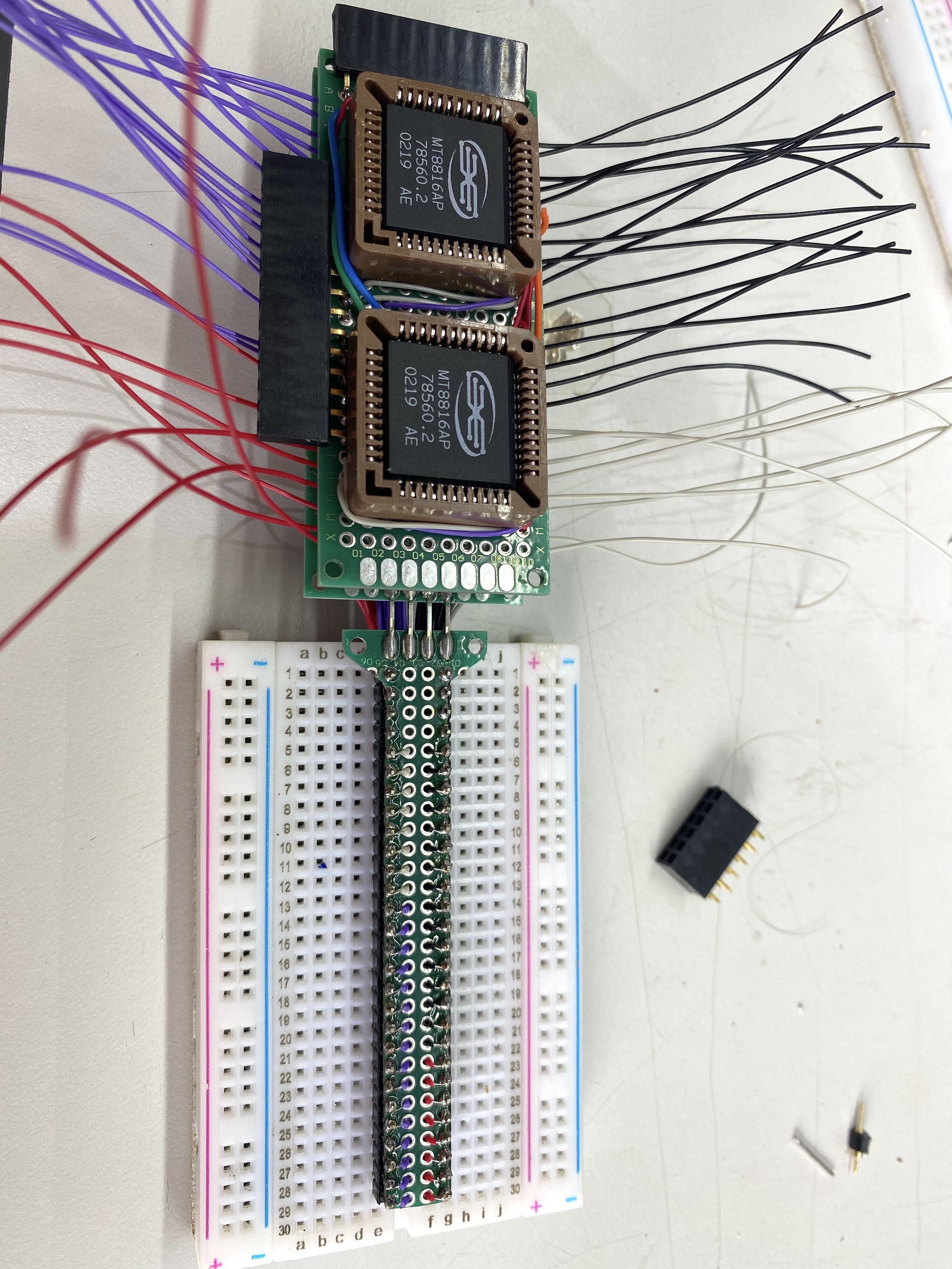
I also wanted to make it not take up the whole breadboard so I could actually test it on real things.
Disclaimer: what I wrote above is a lie, the real reason I made this is because I had just discovered the joys of wire-wrap wire and I needed an excuse to use it.
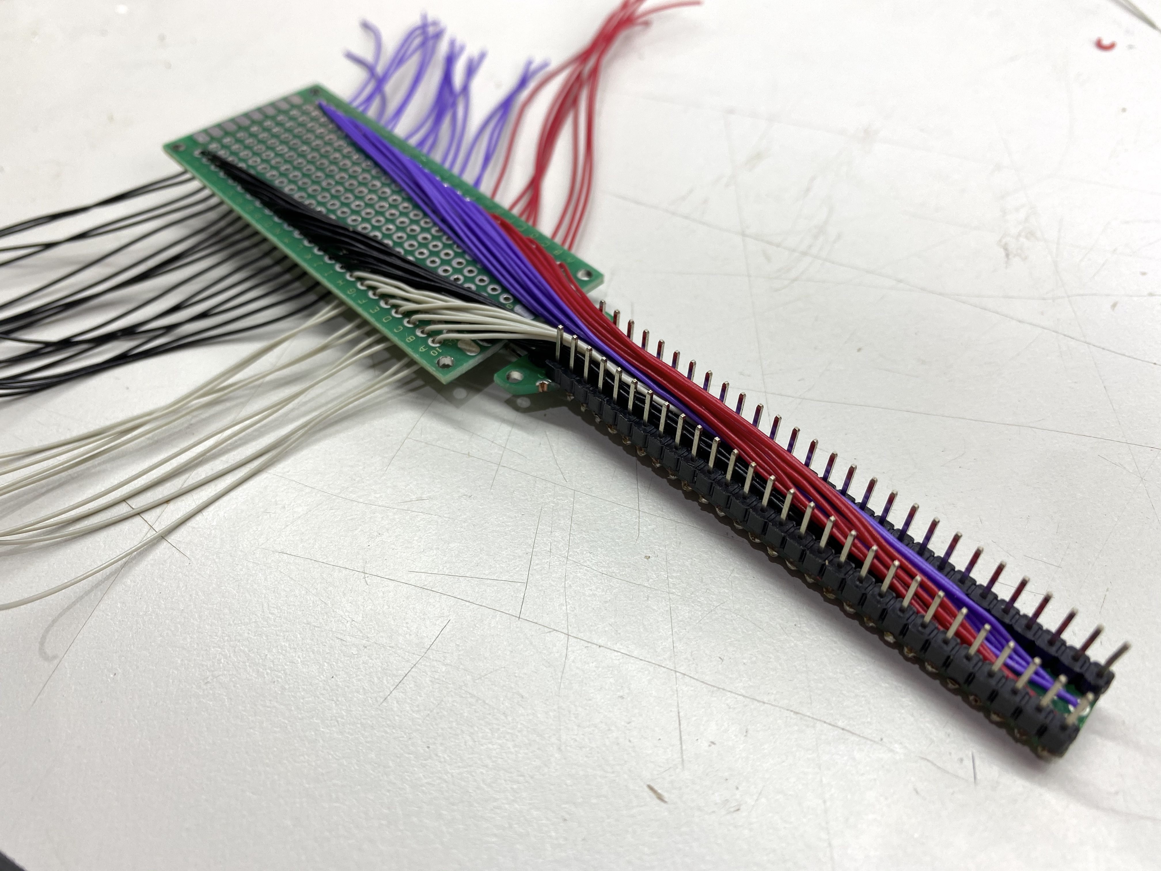
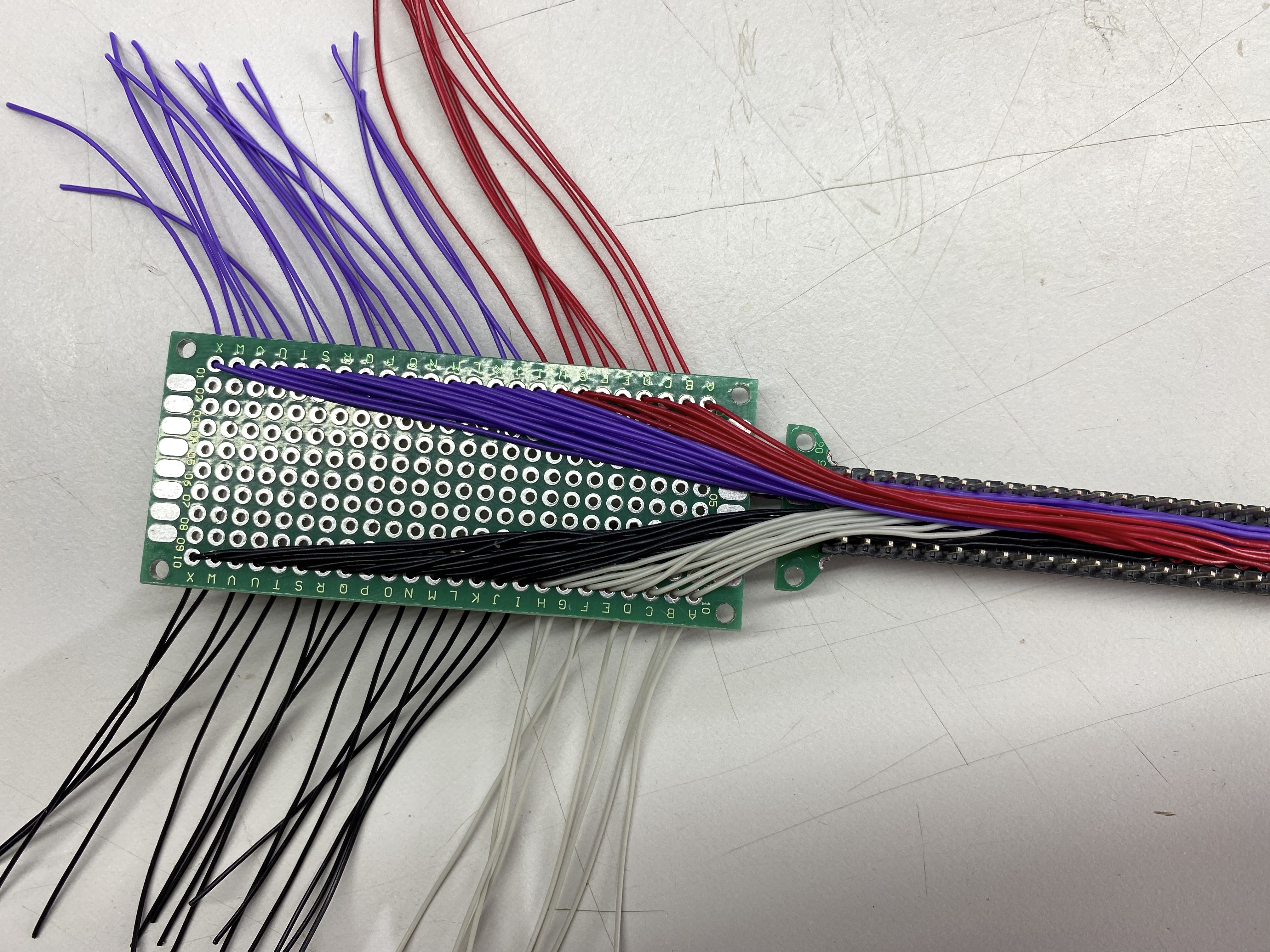
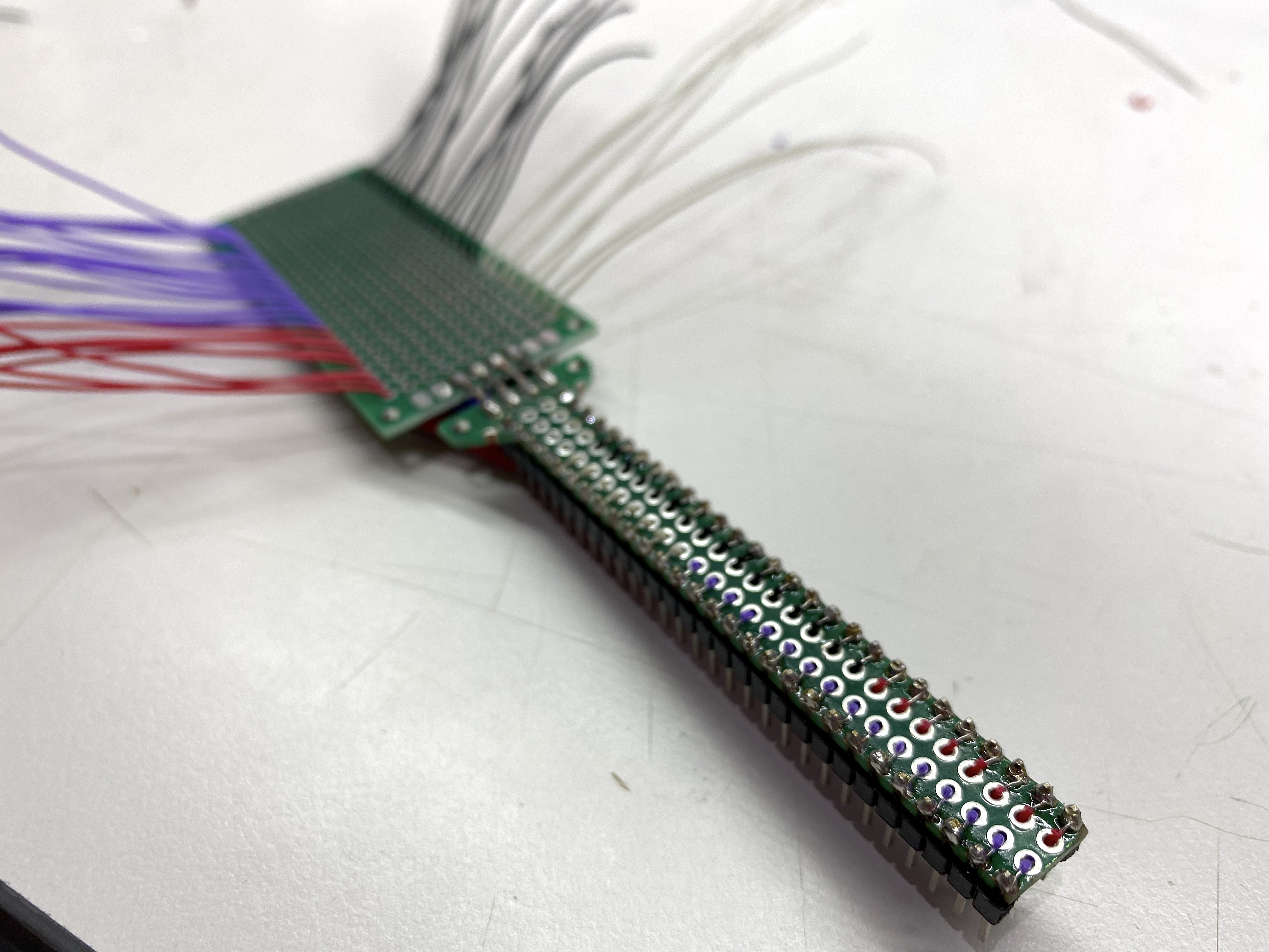
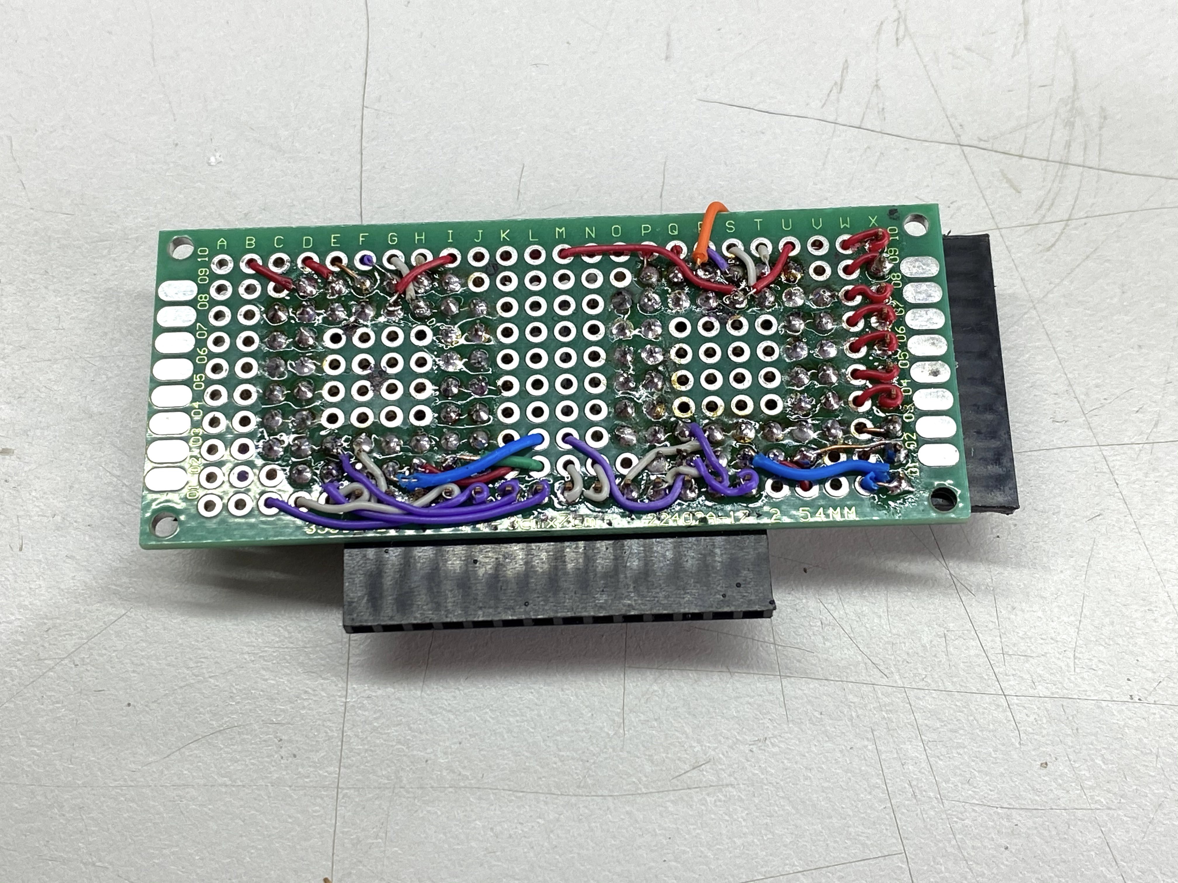
What follows is basically a slideshow of me building this thing.
![]()
![]()
![]()
![]()
![]()
![]()
![]()
![]()
![]()
![]()
![]()
![]()
![]()
This is the pinout for the rows of wires going to the Arduino Nano Every
Control Lines (top to bottom) (left side of board)
CS A
DAT A
STB A
RST AB
CS B
DAT B
STB B
Vdd +
Vss GND
Vee -
Address Lines (left to right) (bottom of board)
Y0 A
Y1 A
Y2 A
X0 A
X1 A
X2 A
X3 A
Y0 B
Y1 B
Y2 B
X0 B
X1 B
X2 B
X3 B
-
Early Proofs of Concept
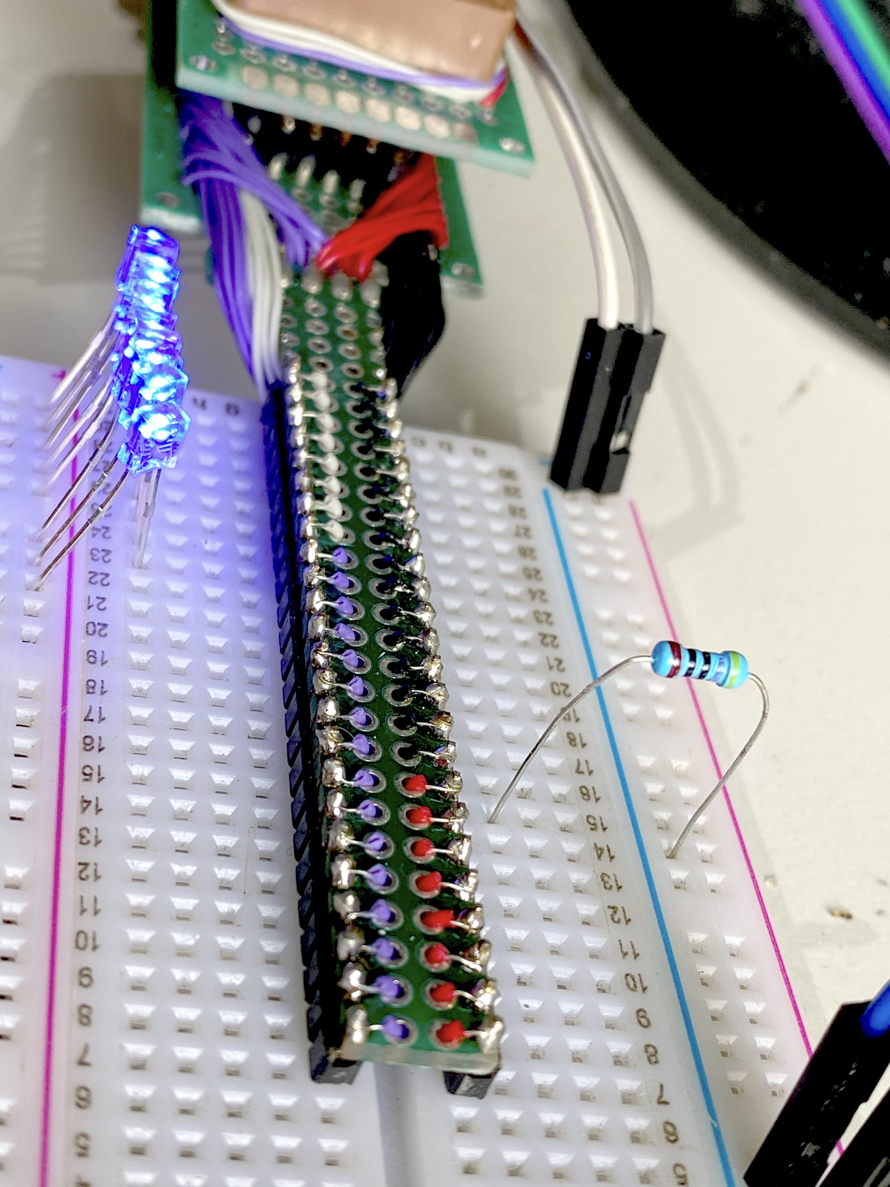
06/16/2021 at 11:40 • 0 commentsHere are some photos and videos of early proofs of concept to make sure you could actually use a crosspoint switch to make a reasonable stand-in for a physical jumper. I was expecting this not to work, but surprisingly, it did.
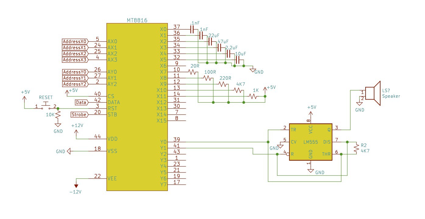
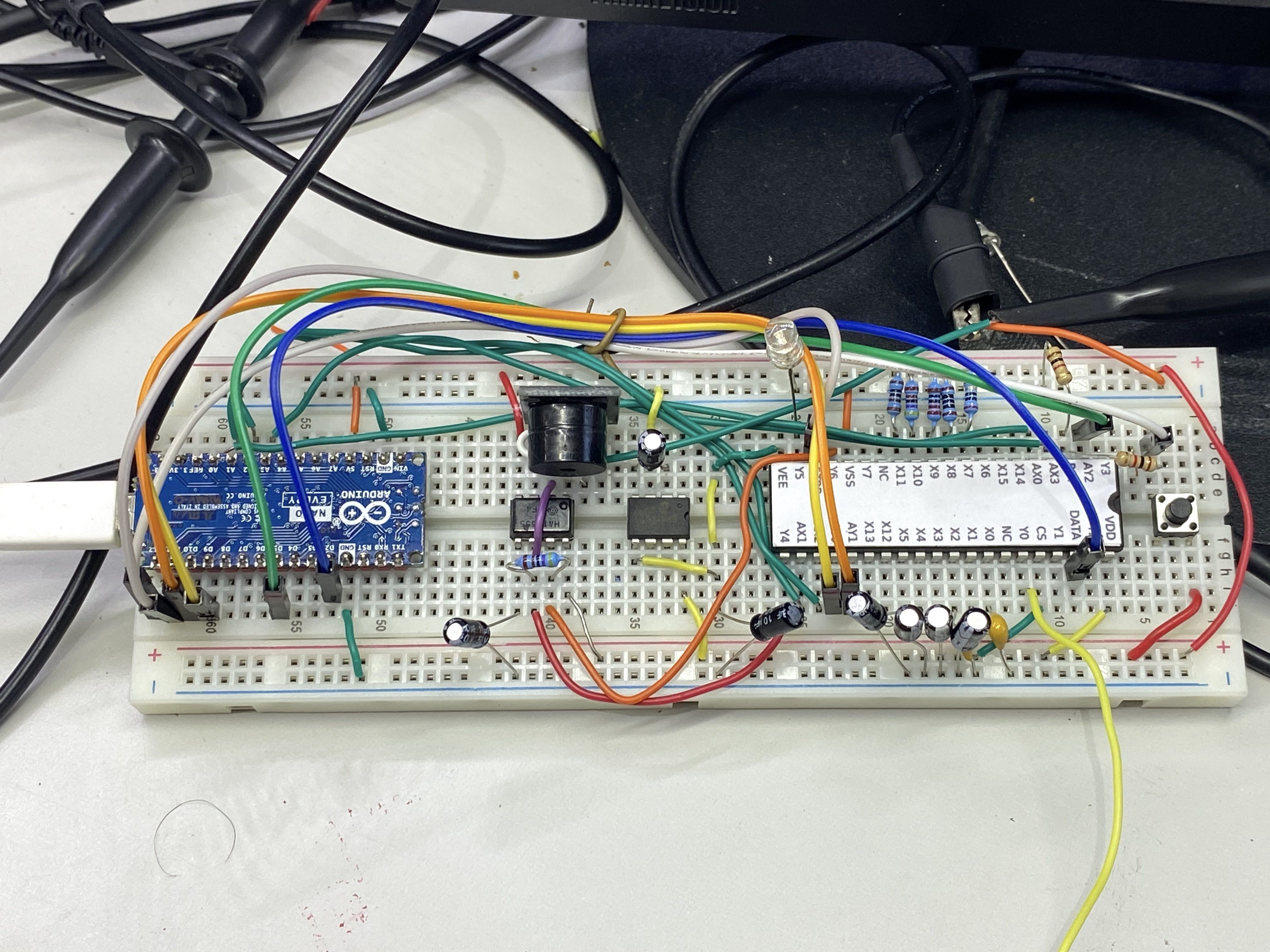
Here's the 555 test setup. I'm using a DIP version of the MT8816 which was really handy for this early testing stuff.
![]()
![]()
and here it is working here's the code for this
What I'm doing here is using the crosspoint switch to change the resistors and capacitors in the 555 circuit to change the frequency.
That other 8 pin chip on the left is a charge pump to make the -9v power rail.
Then I realized I should probably do something more intuitive for the students so I set this up with LEDs
 And here it is after removing one of the D's