Introduction
Quantum mechanics is a fascinating subject, among other things because it introduces truly random processes. In classical mechanics, all movements are deterministic. So while we cannot predict the outcome of a coin toss or throw of some dice in practice, in principle it is possible to know exactly what will happen if all the forces acting on the coin or dice are known. The outcome of a single quantum mechanical measurements on the other hand is (for all we know) actually truly unknowable in advance. Only probabilities can be predicted.
The aim of this project is to harness this property and create a true Quantum Random Number Generator. As a source of quantum randomness, I have chosen the radioactive decay of Americium-241. It is readily available as the ionisation source for ionisation chamber smoke detectors. In fact, the ionisation chambers can be used directly.
Principle of operation
The idea is simple:
- Apply a voltage to the ionisation chamber and amplify the current.
- Measure the variations in the current caused by random fluctuations of the radioactive decay.
- Turn the current variations into a bit stream.
The devil, as always, is in the details. And it took me quite a bit of experimenting to get this working.
The ionisation chamber
The ionisation chamber with the Am-241 was easy to come by for a few bucks on eBay. It consists of a metal body (1), a central electrod (2), and an electrode that holds the Americium (3):
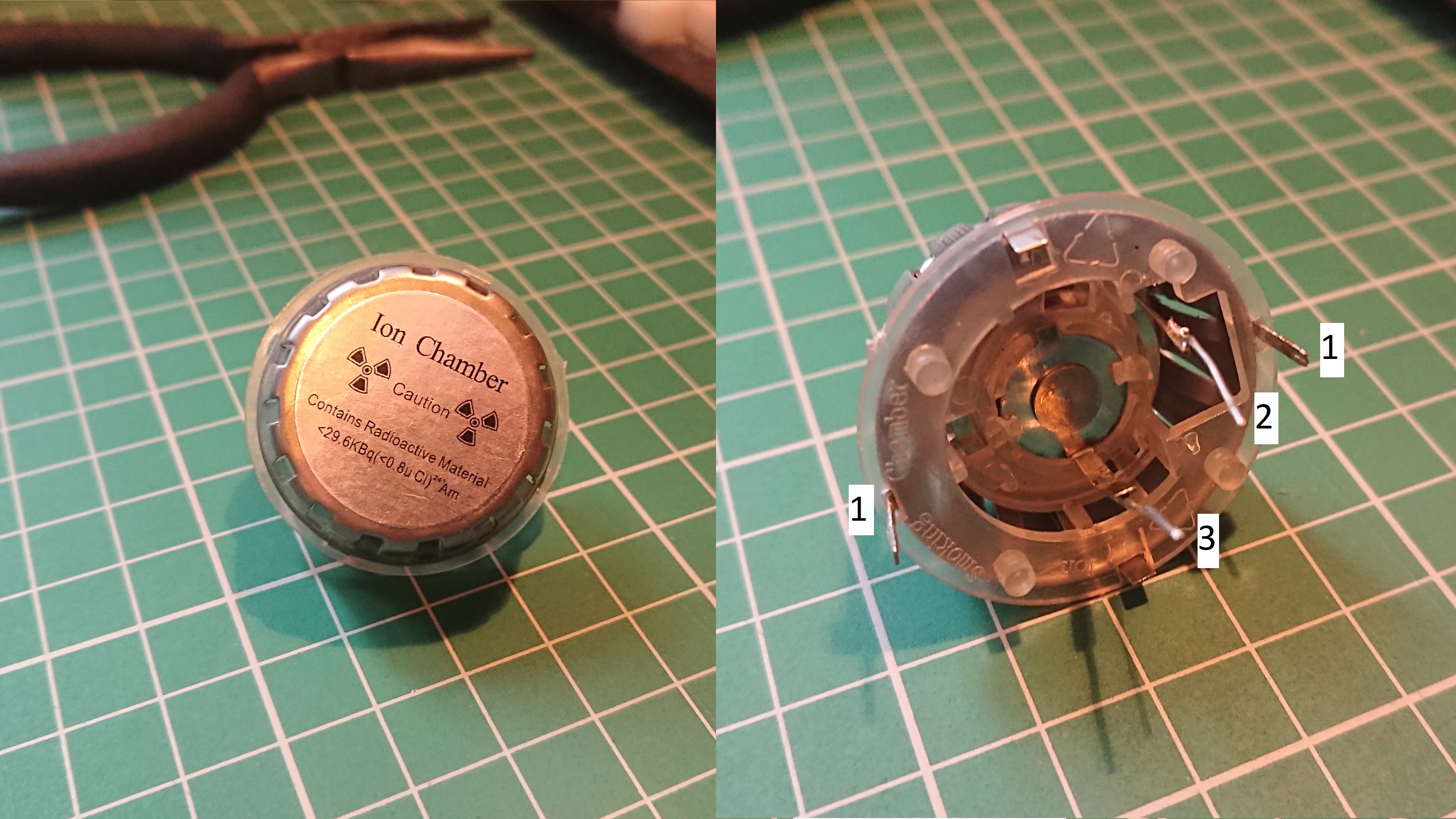
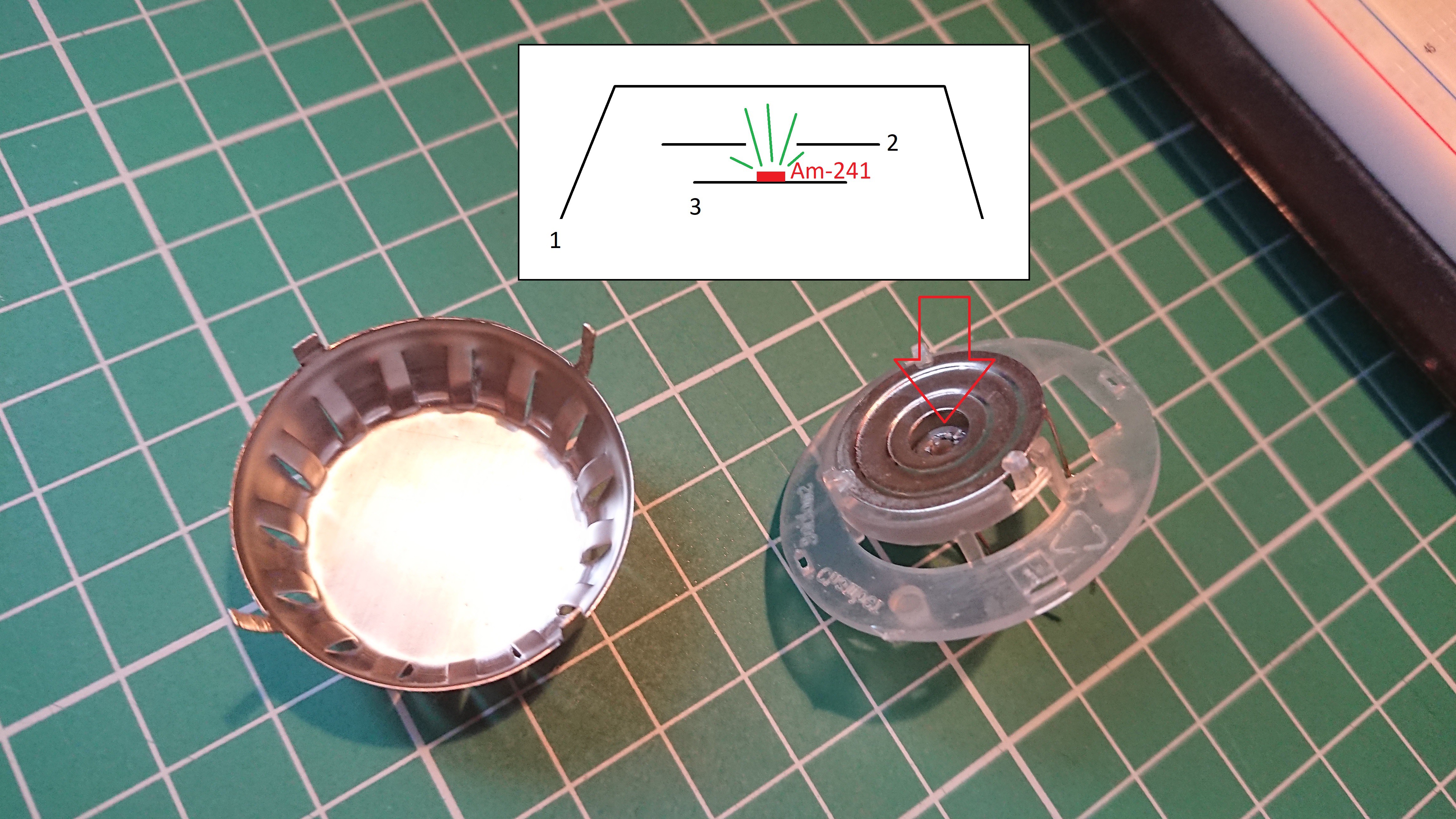
Americium-241 is an alpha radiation source. The alpha particles (shown in green) ionise the air inside the chamber and make it weakly conductive. When applying a voltage between the electrodes and/or the body, a tiny current flows. The amount of current depends on the amount if ions in the air, which in turn depend on the number of Am-241 decays per second. The radioactive decay is a truly random process and thus the current should fluctuate accordingly.
The preamplifier
The current through the ion chamber is tiny. To get it to a measurable level, I put together a preamplifier using bipolar transistors:
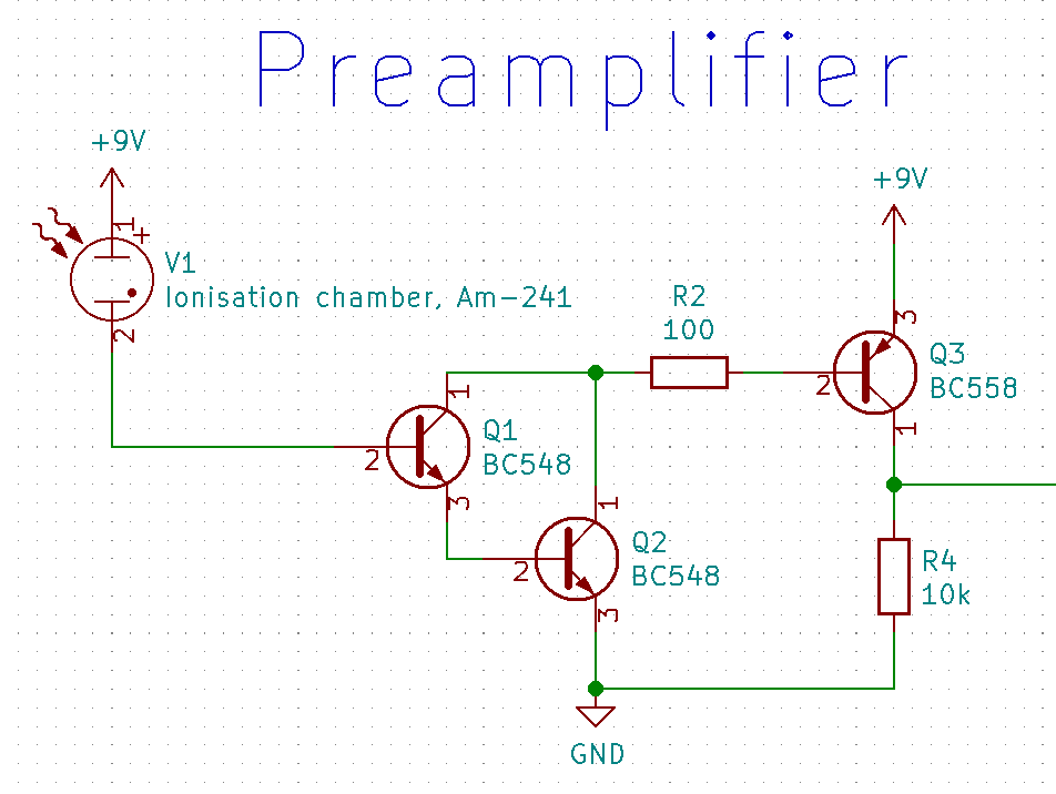
The transistors Q1 and Q2 are configured as a Darlington pair for a large current gain. Q3 adds an additional amplification stage and together with R4 turns the current signal into a voltage against ground. R2 limits the maximum current through Q1, Q2, and Q3, since even small currents could make the Darlington pair become fully conductive.
This circuit is very sensitive. Without shielding it picks up the 50 Hz noise of all the appliances around it:
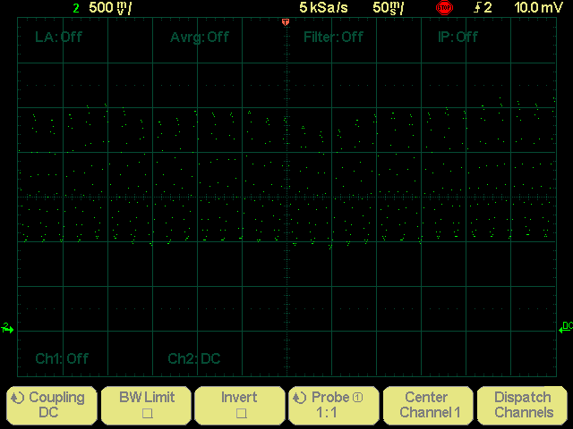
And with proper shielding it produces a signal with a mean value of about 1.5 V and variation in the order of 100 mV:

The low-pass filter
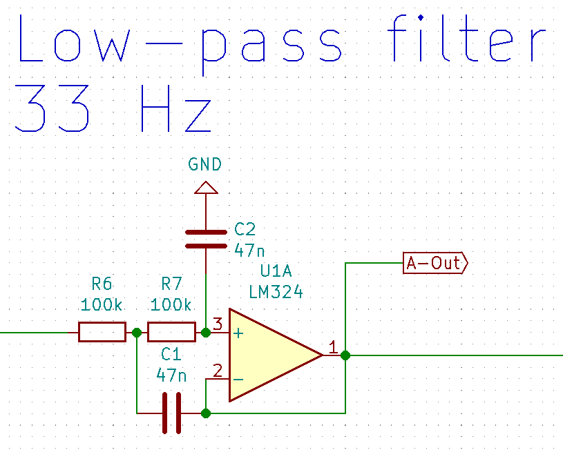
To get rid of any noise that makes it past the shielding, and to turn the high-impedance output of the preamp into a low-impedance signal, the next step in the signal path is an active low-pass filter. I used this very handy online calculator to design it. It has a cut-off frequency of 33 Hz.
The comparator
The analogue output of the low pass needs to be turned into a digital signal somehow if we want to use it as random bit stream. For this I am using an OpAmp as comparator.
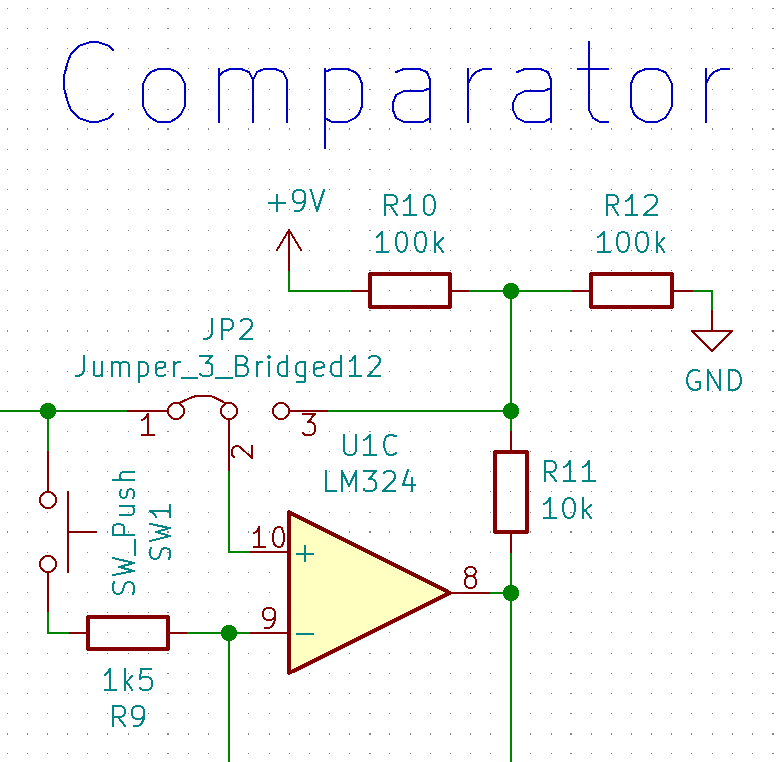
The output goes high if the input signal (coming in from the left) is above the reference voltage (coming in from the bottom left) and goes low when it is below. The switch SW1 is there to jump start the reference voltage generation when powering up the circuit. Jumper JP2 as well as R10, R11, and R12 are used when fine tuning the reference voltage generator. This will be explained in more detail later.
 Lukas Koch aka Ast






 Jan Waclawek
 Evangelos Petrongonas
 Grant Giesbrecht
 Mitsuru Yamada
hello, I would like to discuss with you your project about a quantum random number generator, to be honest, I don’t understand why one thing is written on the diagram and a little different in the photo, for example, 2 diodes were used there although they were not in the diagram at all. Or a variable resistor that is located next to americium. I would be glad if you answer the questions or at least respond to the message