-
Rev 2 board manufactured and assembled
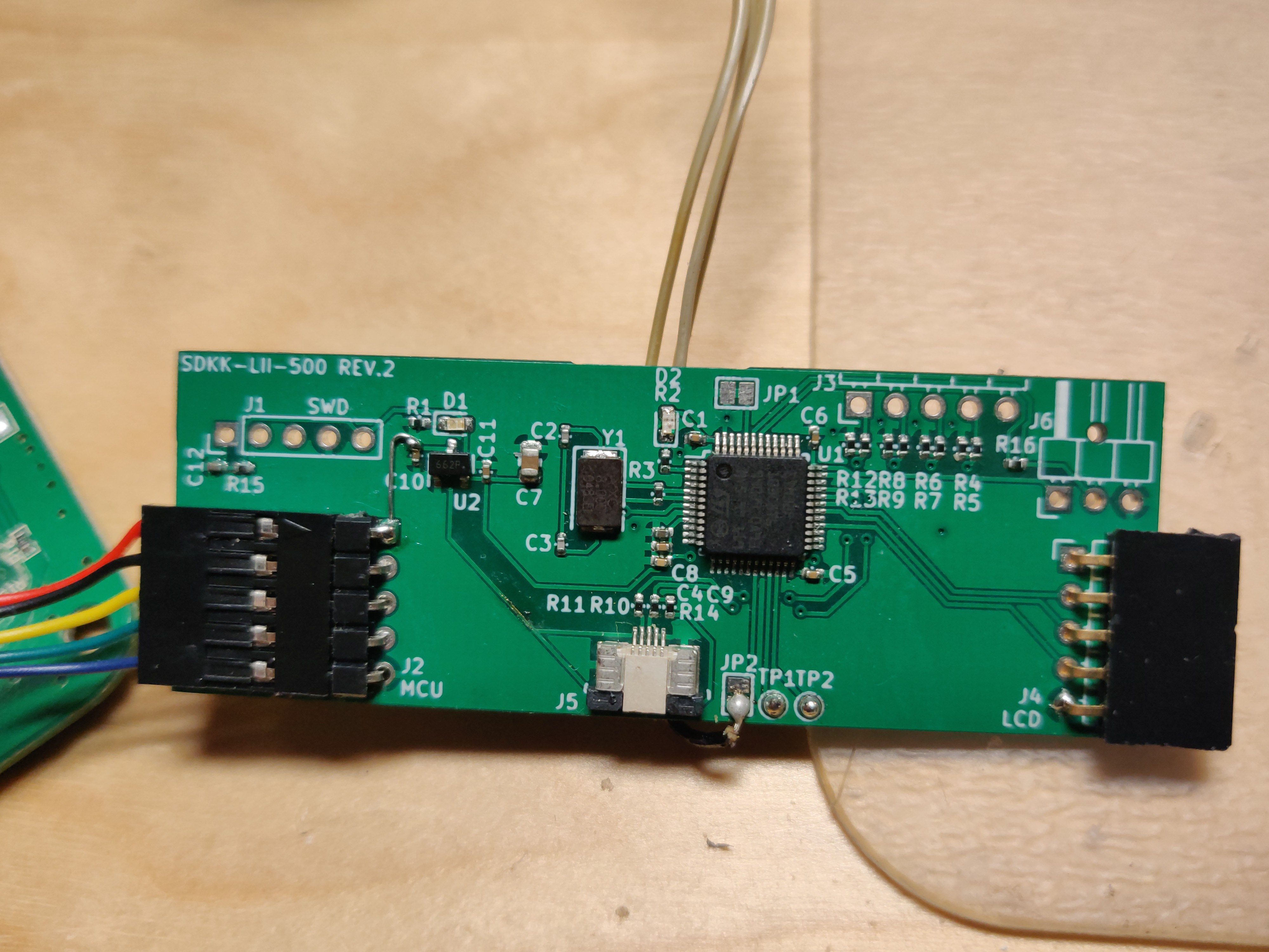
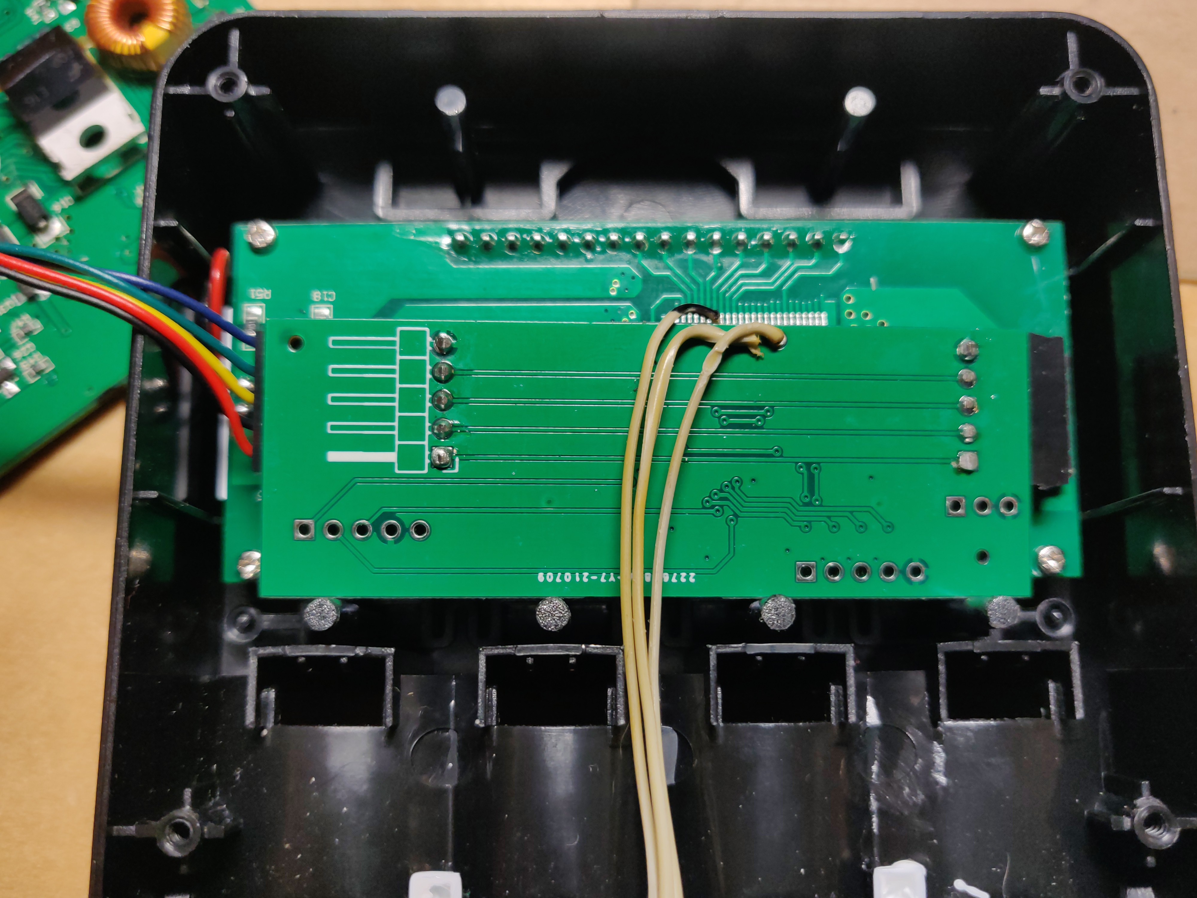
08/05/2021 at 20:35 • 0 commentsThe REV 2 board has been manufactured and has been lying on my desk for a while now. Today I finally had time to solder connections, flash firmware and assemble everything:
![]()
Unfortunately I found out that I have made two rather big mistakes with the board:- The FPC connector for the USB cable should be 1mm pitch not 0.5 mm.
- I put the LCD and MCU connectors "backwards" :).
The board was plugged into the LCD on the back and connected with a serial port instead of USB, the firmware now allows you to choose :).
![]()
-
The sidekick board
07/03/2021 at 22:53 • 0 commentsIn order to make the entire idea easier to use I have began developing a custom PCB with streamlined connectors and small footprint. The board is basically a STM32 Blue Pill remixed for this application. The Kicad project of the REV1 board can be downloaded here.
-
LCD Controller Identified
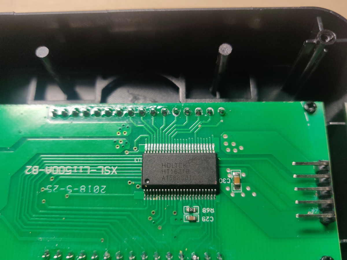
07/03/2021 at 11:26 • 0 commentsBy disassembling the next charger I discovered that it's LCD module contained a marked chip as the LCD controller:
The chip is Holtek 1621B the datasheet is easily found. As I have previously reverse engineered the protocol from scratch I was happy to find that everything matches with what the datasheet describes. The LCD driver chip has much more features than are used by the MCU (for example a watchdog timer). The one interesting tidbit is that the LCD driver chip contains no GPIO pins to drive a transistor controlling the backlight. What the designers choose instead is to reuse the buzzer outputs for the backlight driver. When the LCD backlight enable command is sent the buzzer output is configured to output a 4 kHz tone for the buzzer which I assume drives the backlight transistor.
For posterity I have left all of the reverse-engineering process description in the project details.
-
USB now supported
06/27/2021 at 12:47 • 0 commentsThe code now supports sending the SPI data directly via USB with a CDC-ACM serial port profile.
Li-Ion Charger Automation
Automate cell information readout from a Liitokala Lii-500 charger by tapping into it's LCD interface
 Enki
Enki

