Alain Mauer
-
A Small Bug
10/13/2021 at 11:04 • 0 commentsAfter a few weeks of continuous operation, I noticed a small bug. The power low output is sometimes too late. When the voltage is at the minimum and then the voicemodul starts, it can happen that the BOD of the Atmel switches off the processor. I still have to do some tests to reproduce the error and then I will adjust the software. So stay tuned.
After recharge, everything works fine again.
-
The Board Misused
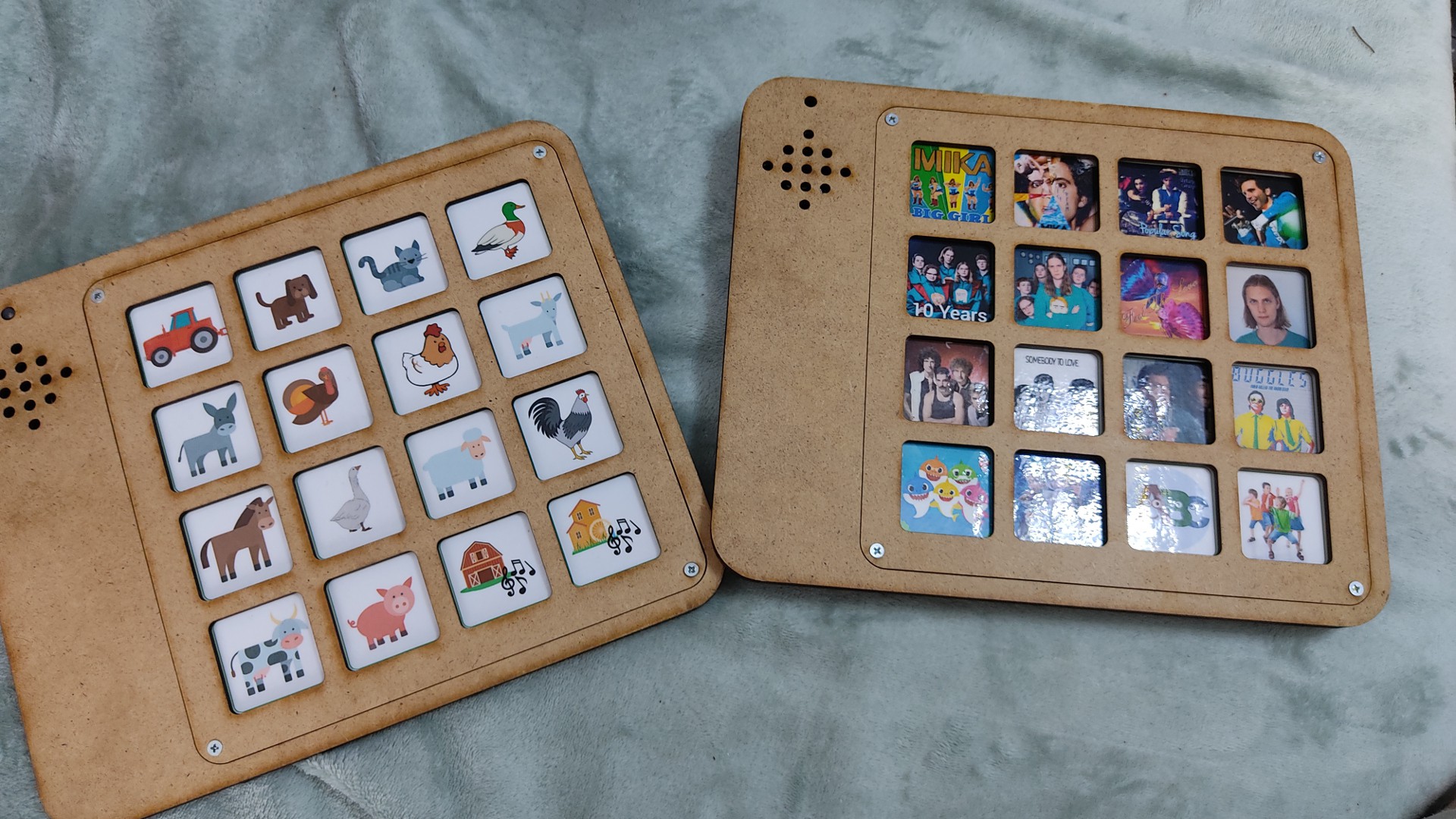
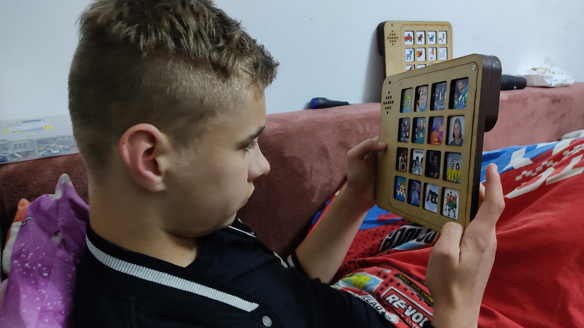
08/17/2021 at 16:09 • 0 commentsScott is still having some problems using his boards as they are meant to be used. That's why they were turned into a game tablet and a music tablet at short notice. In any case, he can keep himself busy with it.
![]()
![]()
![]()
-
Pecs Board = Old Mc Donald
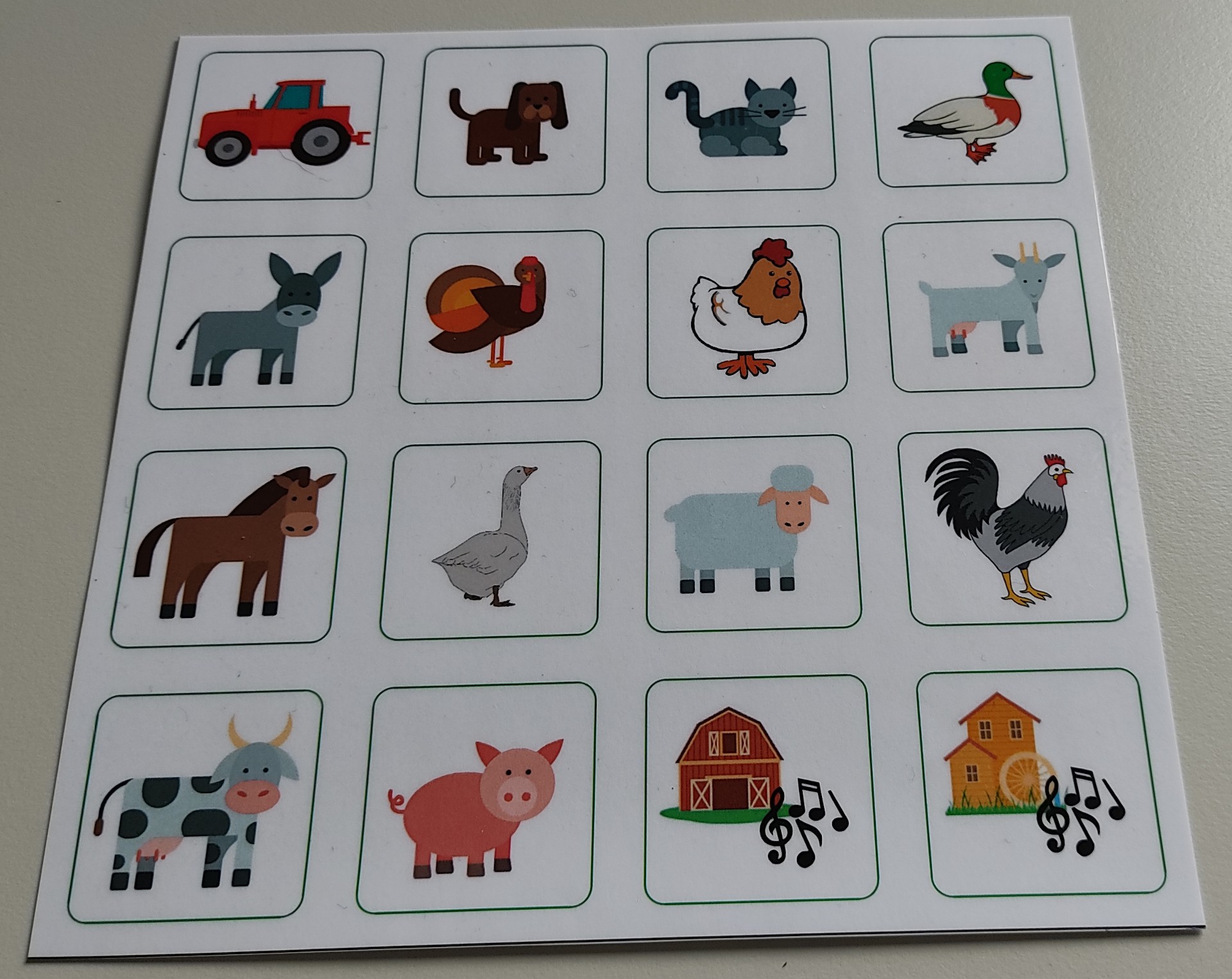
07/27/2021 at 05:24 • 0 commentsScott is still having some problems, understanding, how to use the PECS board. In the meantime, we use it to keep him busy. This time with animal sounds. We have had children's books that made music or sounds, but their survival time with our son was very short. For tonight we have farm sounds and songs.
![]()
-
New Features
07/22/2021 at 13:26 • 0 commentsHello,This should be the final version for the PECS board on GITHUB.
https://github.com/awall9999/ScottCom
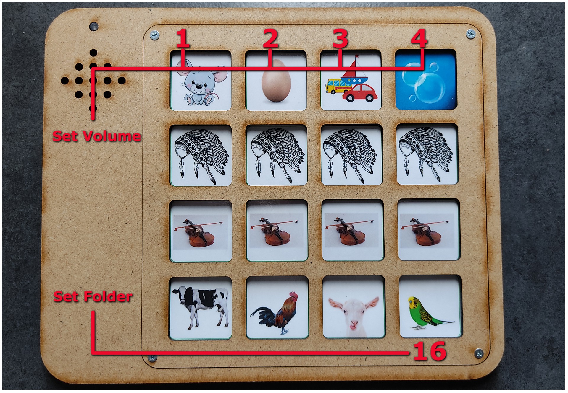
Pecs board_V1.4
- By holding button 1,2,3 or 4 for 2sec, the power LED goes out.That means you have successfully changed the volume, where 1 is the minimum volume and 4 is the maximum volume.
- Selecting a folder is now possible via software. If you keep key 16 pressed for 5 seconds, the power LED goes out. You are now in programming mode. By pressing a key from 1 to 16, you select the corresponding folder.
![]()
-
New Software
07/19/2021 at 07:12 • 1 commentHello,
I have just released the new software for the PECS board on GITHUB.
https://github.com/awall9999/ScottComPecs board_V1.3
- Stop a music file by pressing the same button again.
- Adjust the volume in four steps. Simply press button 1,2,3 or 4 for 2 seconds, until the music file is played as confirmation. 1 stands for silent and 4 for loud.
- The volume setting is stored in the internal EEPROM.
-
The Function LED
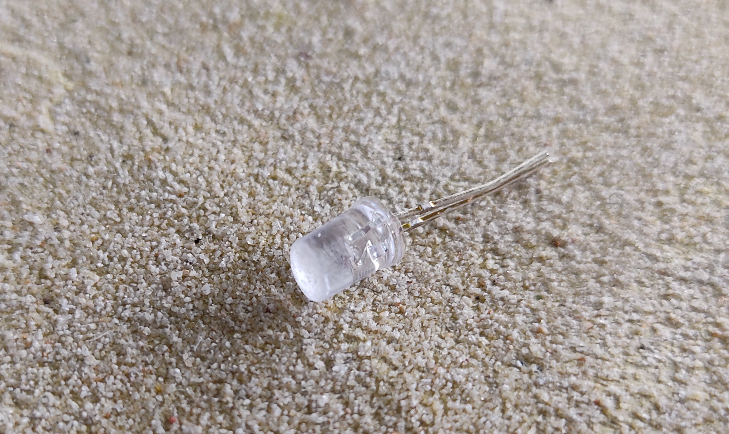
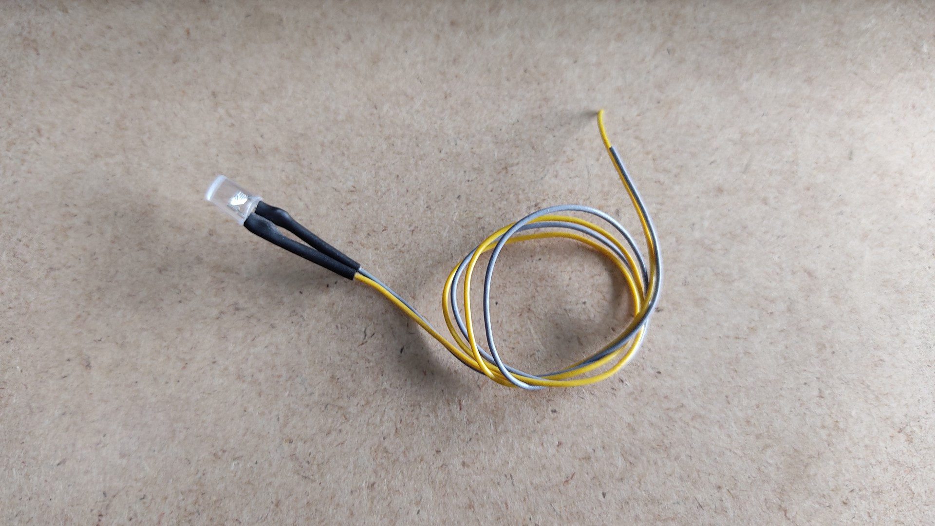
07/16/2021 at 12:32 • 0 commentsFor the moment, the LED only indicates whether the device is switched on or not. But since it is connected to an I/O port, it is also possible to display a programming status, for example.
The LED was grinded at the front, so that it doesn't protrude, and because it is diffuse now, it doesn't dazzle anymore.
Then it can simply be glued in.![]()
![]()
![]()
-
New enclosure
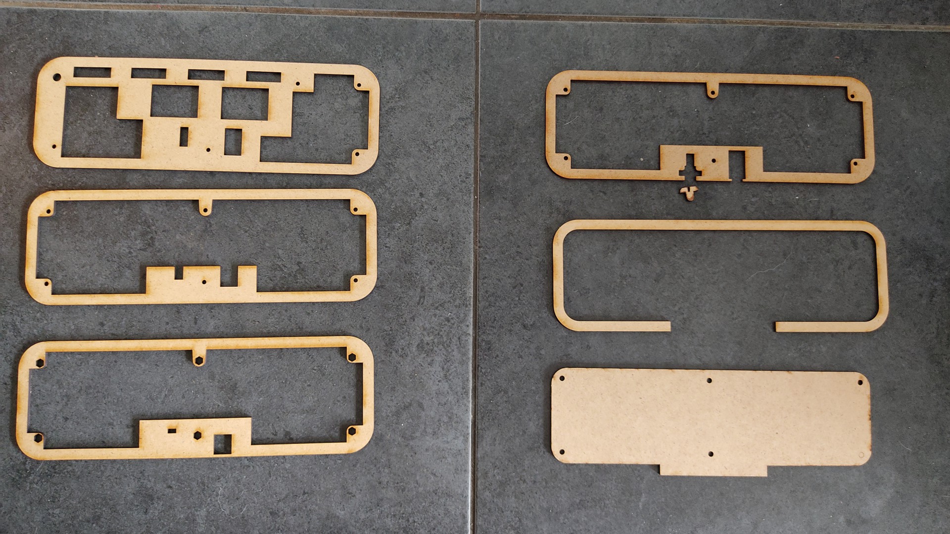
07/16/2021 at 12:25 • 0 commentsI have made some changes to the case. The current plans can always be found on my GITUHB,
I think this way it is easier to assemble the whole thing. Check the BUILD INSTRUCTIONS.
![]()
-
Drawings or photos?
07/09/2021 at 08:58 • 0 commentsPECS pictures are usually simple drawings. However, I have found that Scott does not understand them very well. So I started taking photos of objects, and Scott seems to recognise them more.
So over the course of the week, I'll take pictures of drinks and food and see if Scott can tell me what he wants.Will try to make a video of it
-
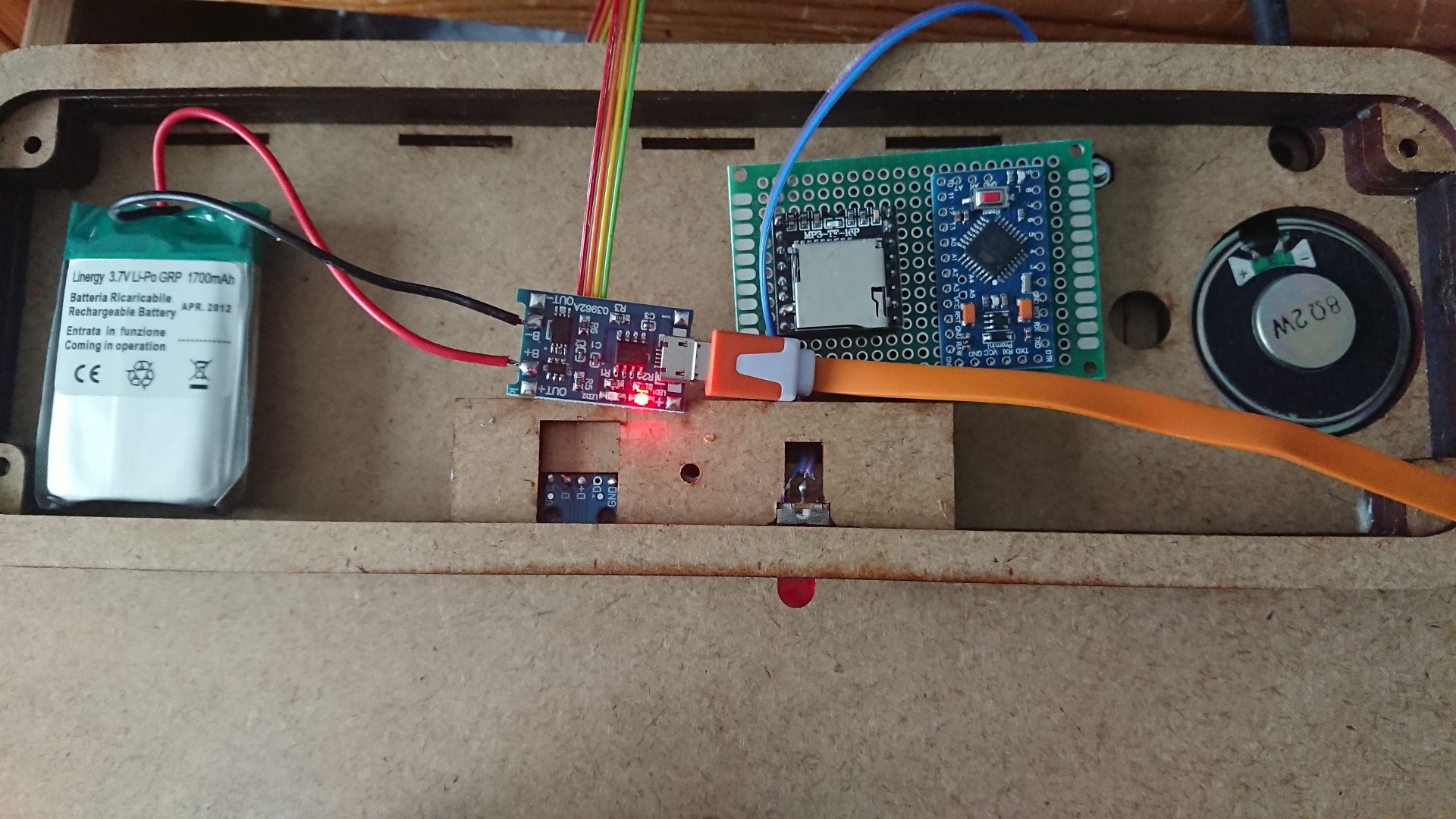
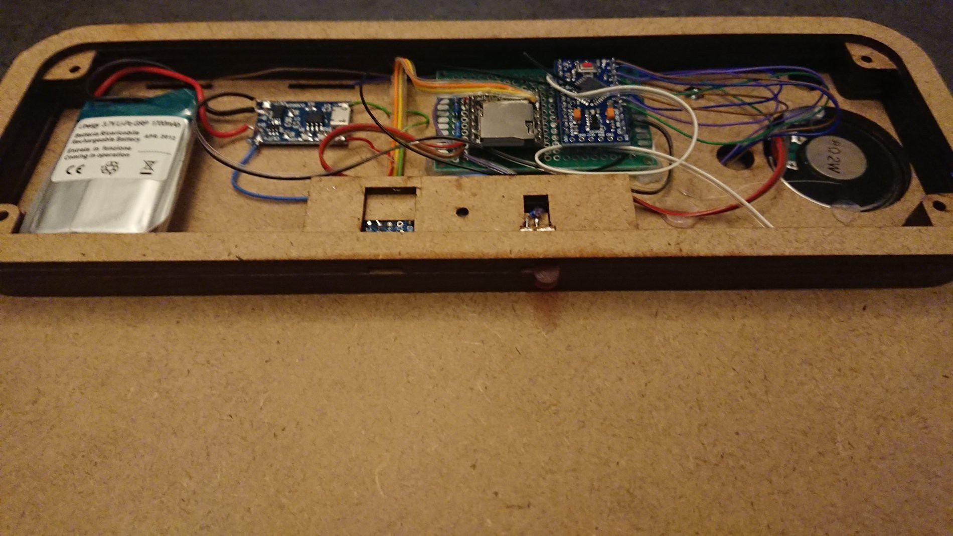
Inside the PEGS Board
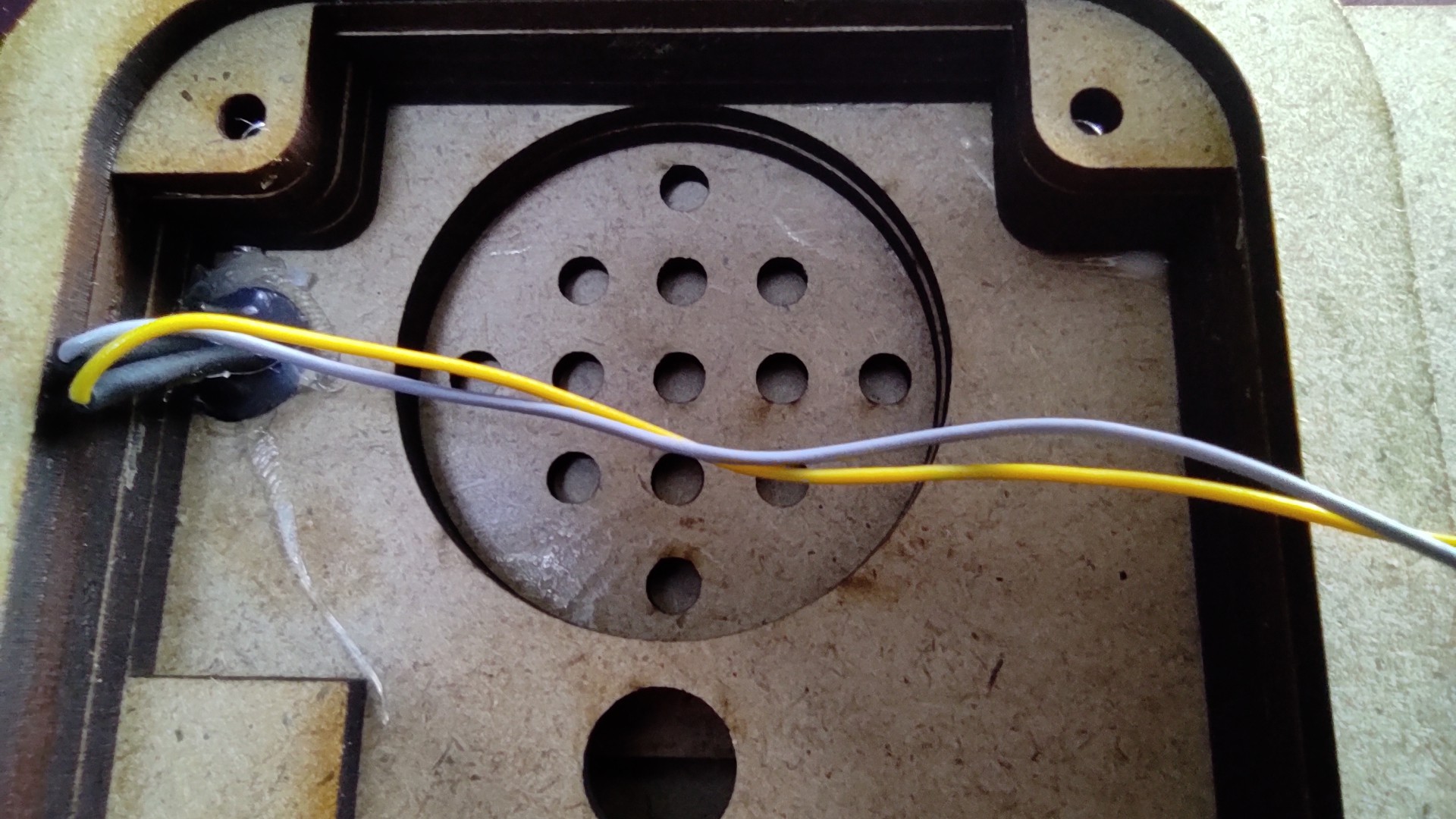
07/06/2021 at 10:29 • 0 commentsAll the electronics are mounted on the back of the PECS board. The heart of the whole thing is an Arduino Pro Mini that runs at 8MHZ, so it only needs 3.3V. A DF mini player with micro SD card is responsible for the sound. A TP4056 charging module charges and controls the battery.
The DF mini player has 2 Watt output power, which is quite sufficient. Its TX and RX lines are connected to the Arduino. This allows the microcontroller to retrieve the files directly.
I have written a small manual for the DF mini here.
Its USB+ and - lines are soldered to the USB connector. This way the MP3's can be written directly from the PC to the SD without having to remove it. At the same time, the battery is charged via the USB connector.
The 8 wires of the matrix are also soldered to the Arduino. A voltage divider on the microcontroller monitors the battery status, and at 3.4V it issues a "Battery Low" warning.![]()
![]()
-
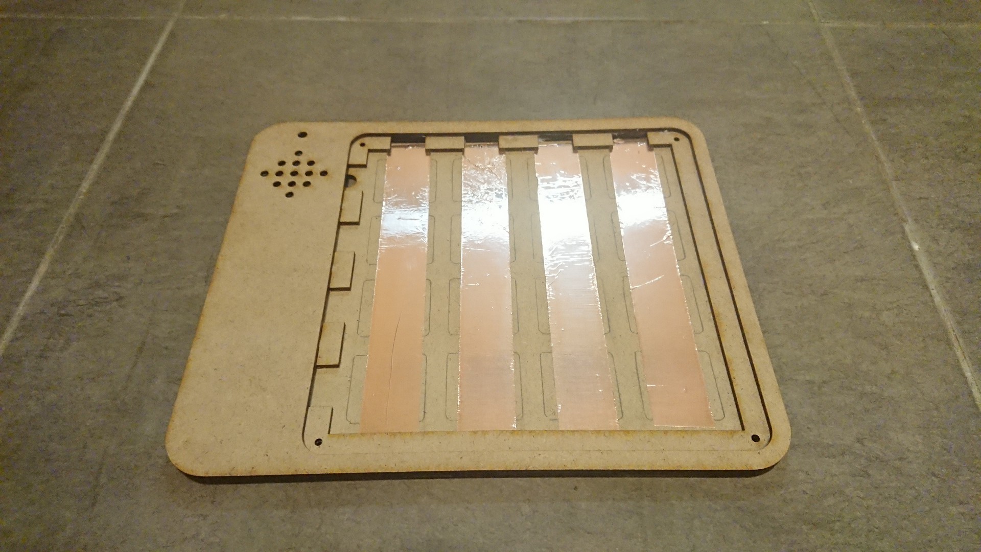
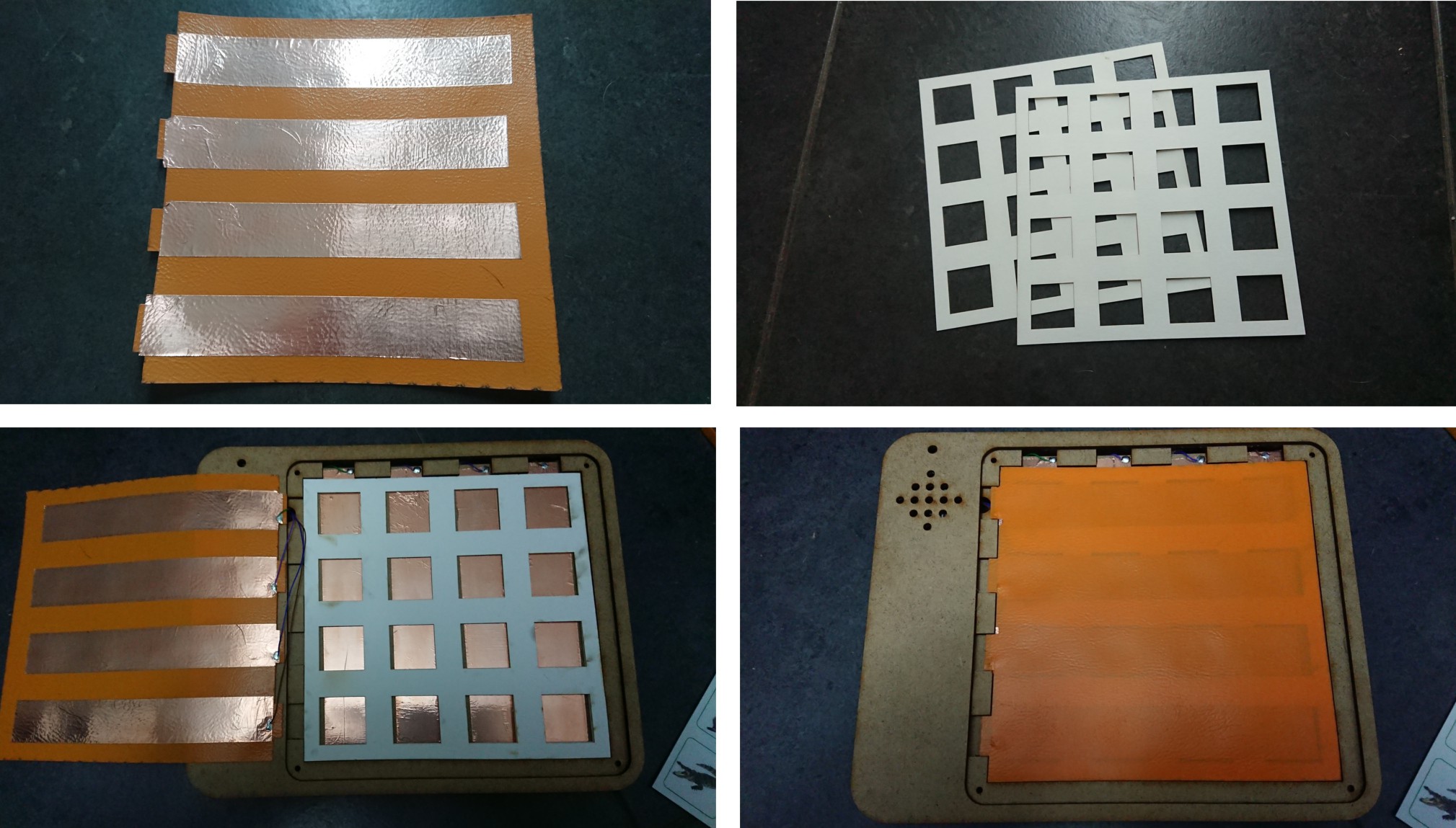
The Buttons
07/06/2021 at 06:02 • 0 commentsFor the sixteen buttons, I built a DIY membrane keyboard. Self-adhesive vertical copper strips are glued to the underside.
The upper side consists of adhesive copper foil applied horizontally to a plastic sheet from a loose-leaf binder. Cardboard was used to separate the two foils.
Then the wires could now be soldered to the copper strips, four to the back and four to the membrane.
![]()
![]()
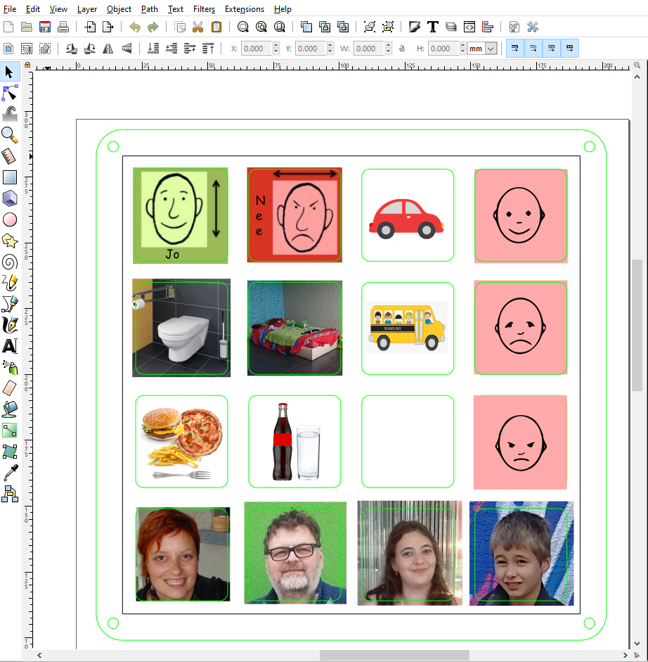
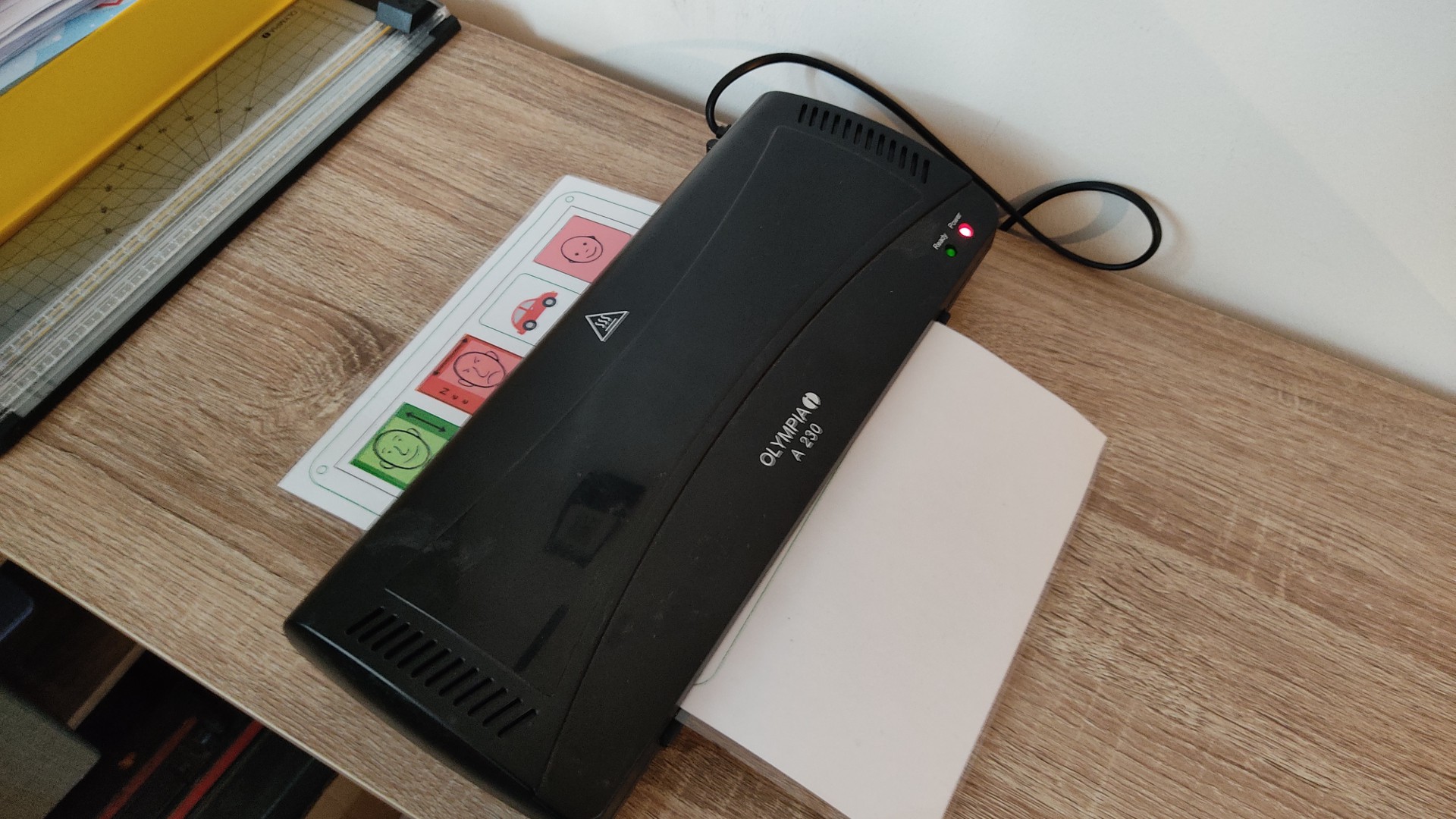
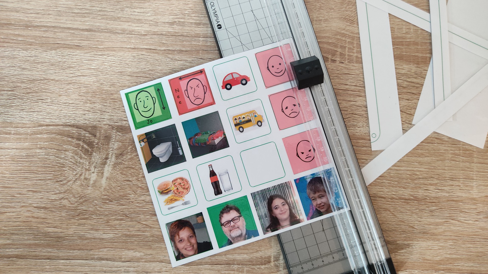
The cover sheet with the pictures is simply a printed picture for which a template has been created so that you can make them yourself without any problems. Afterwards, the sheet is simply sealed in laminating foil so that the pictures are protected against abrasion.
![]()
![]()
![]()
PECS Communication Board
It's a Picture Exchange Communication System (PECS) for my non verbal Son