Jonathan
-
AC Phase Controlled Humidifier: Part 1
09/18/2021 at 16:35 • 0 commentsHumidifier Test: 100% RH
Controlling Fan Speed:
To control the humidity, the humidifier fan throttles up or down to reduce or increase the amount of humidity released into the chamber. The Fan speed is controlled by a single channel AC phase control module (Dimmer), the dimmer is connected to an Arduino Mega2560 that receives serial commands from the Raspberry pi zero W. The phase control module uses a zero-point cross detector and a triac gate to track every single wave of the 60Hz AC entering the device. For each half of an AC wave the Arduino Mega sends a value indicating how long the triac gate should wait till allowing current to pass through to the device. The longer the wait the less power is output, if there's no wait at all the device will be running at full power.
In the below video I'm running the fan at a medium, low, and then high speed by changing the value returned from the Arduino Mega. The Humidity PID controller will send higher or lower command values to the humidifier fan as the process dynamically responds and eventually settles into the set-point (target) humidity. The medium command was 250, low was 300, and faster was 175; so you can see a smaller wait time correlates to more current and a faster fan.
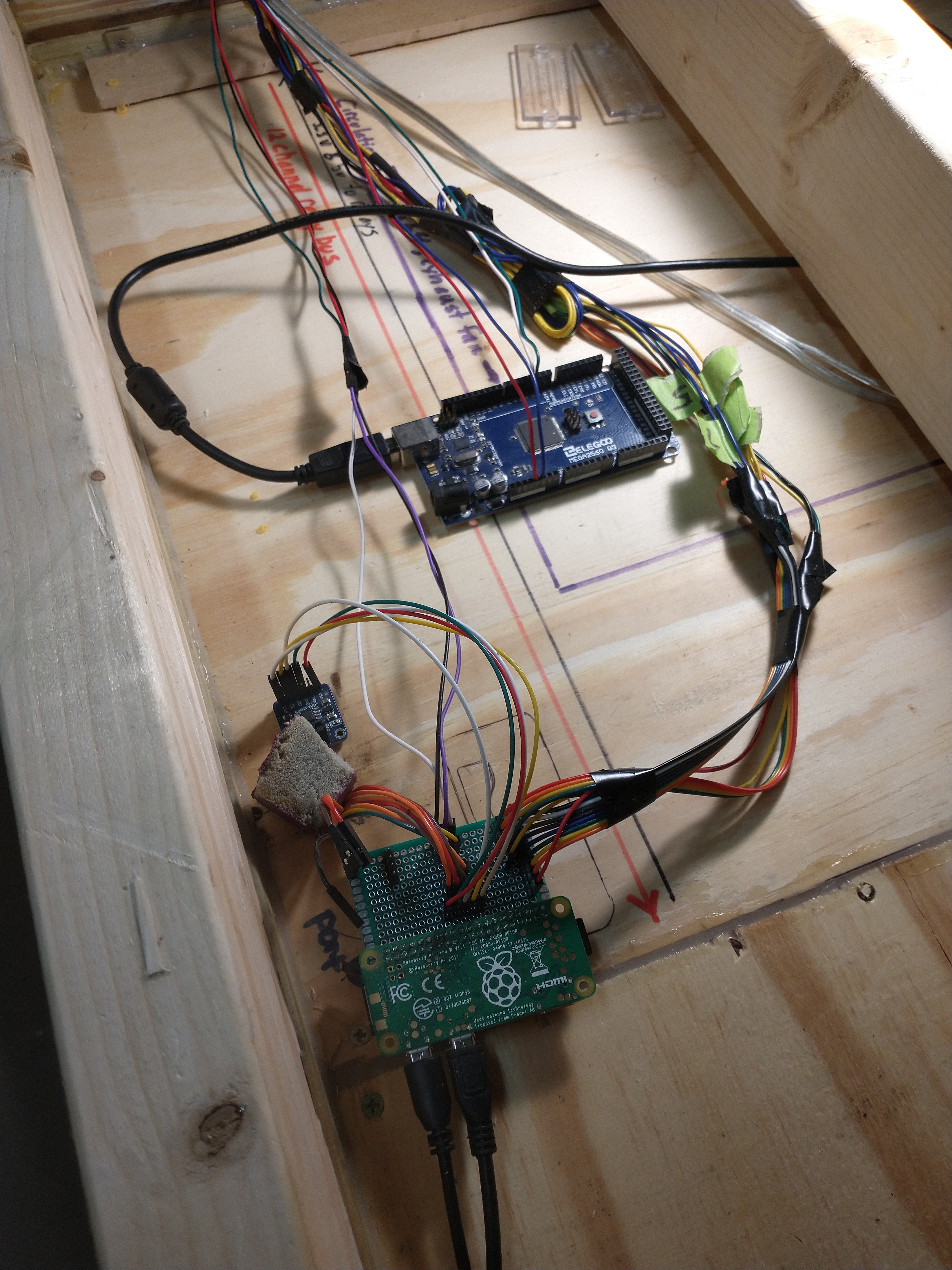
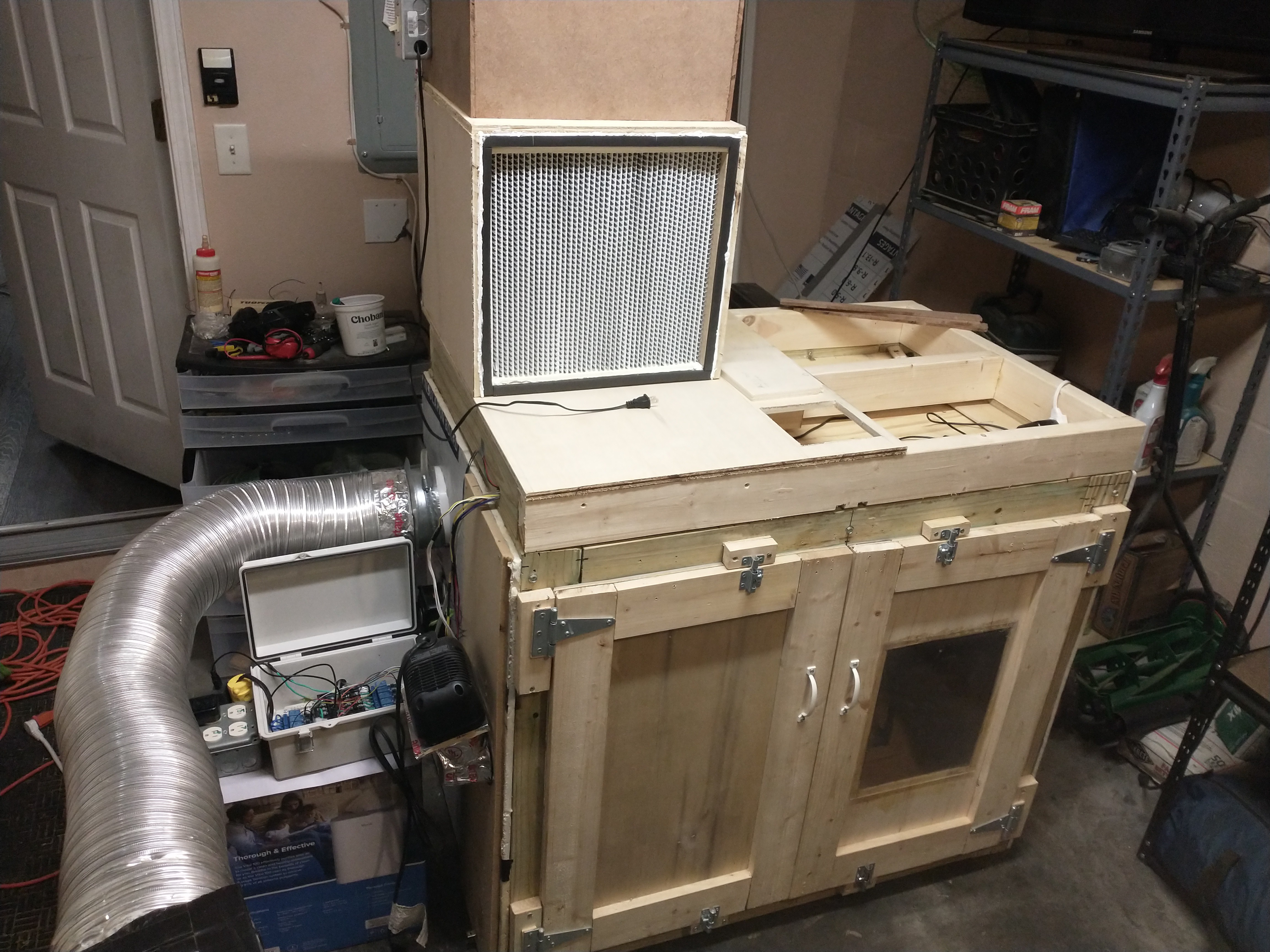
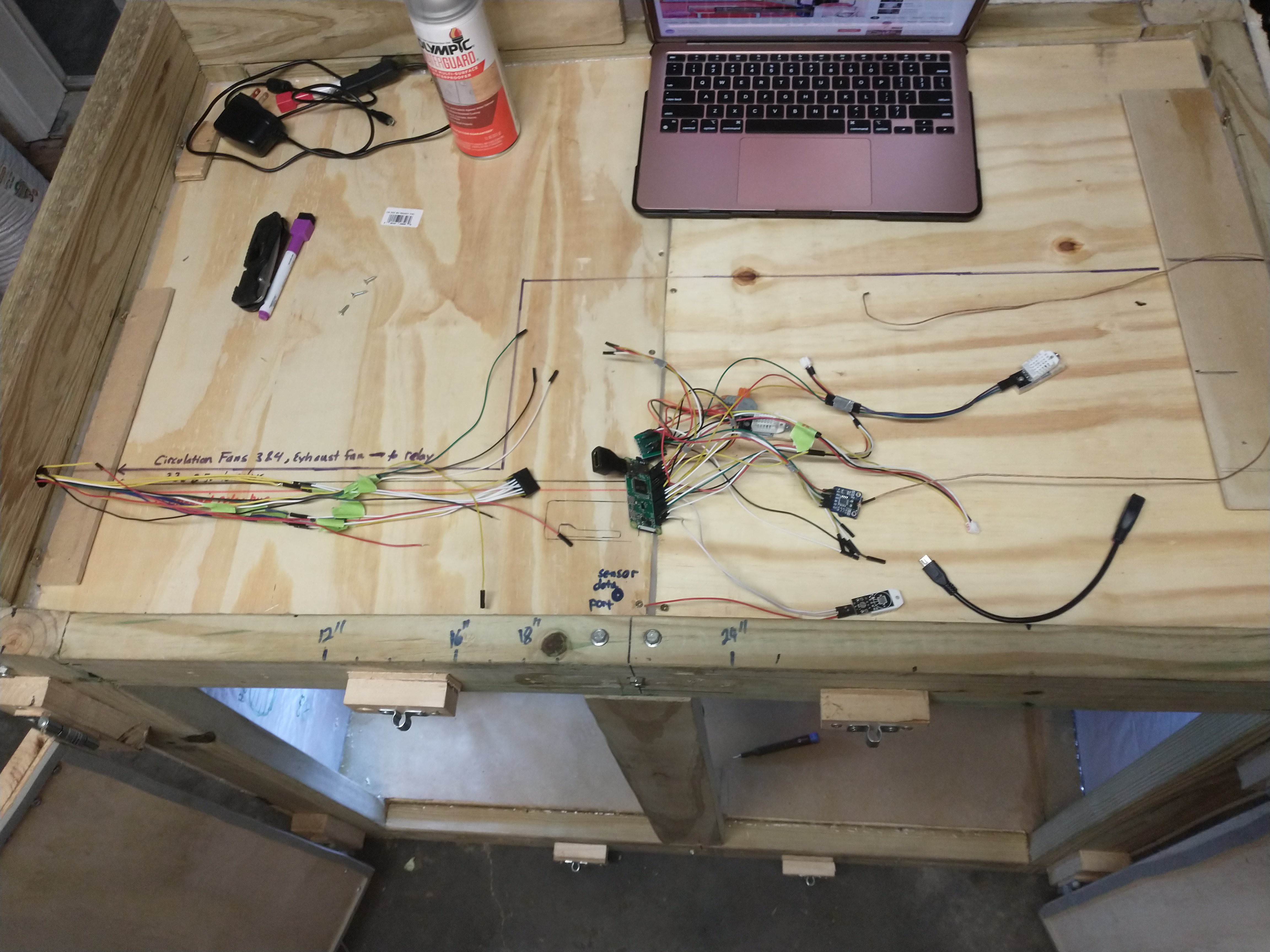
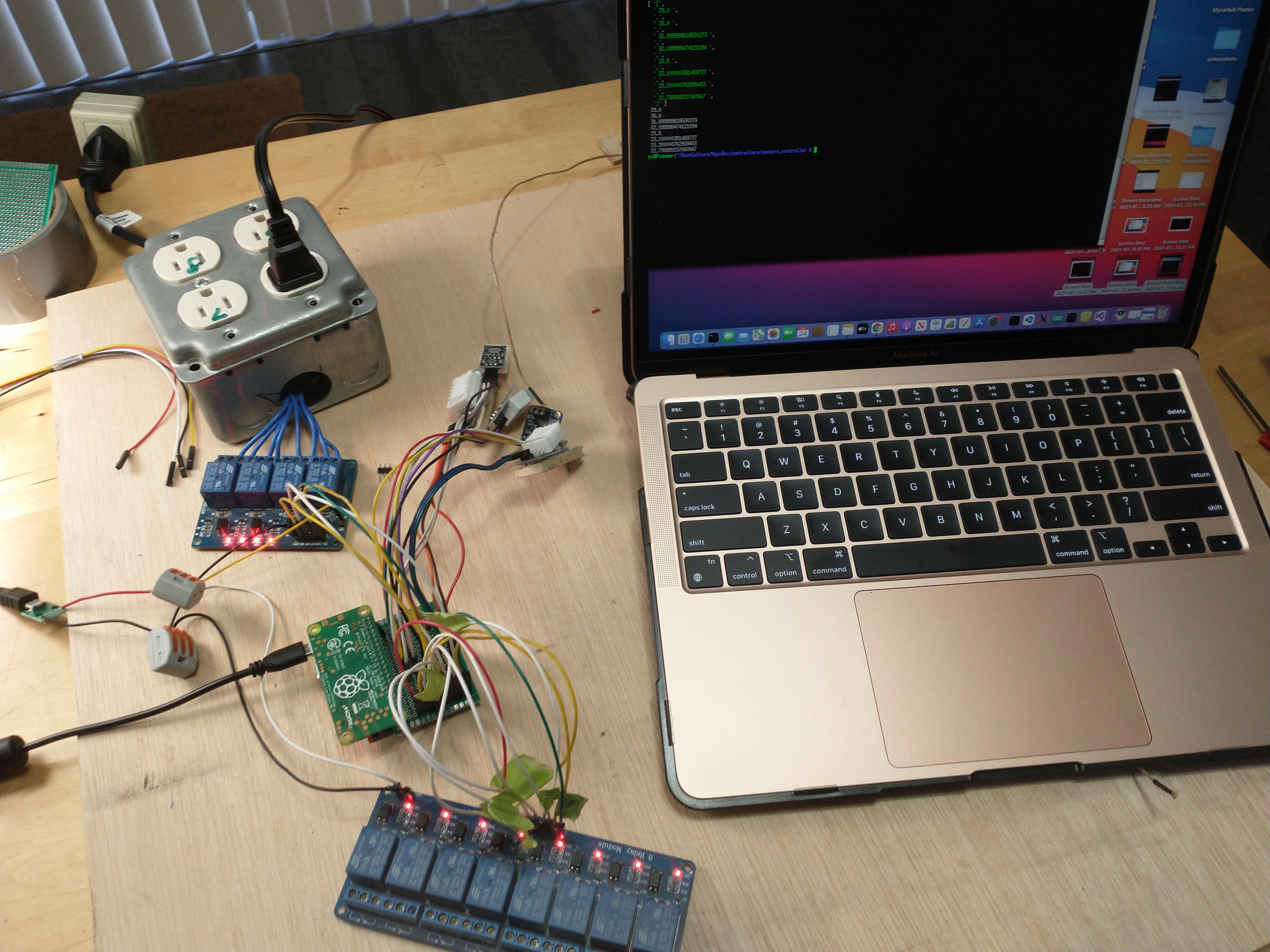
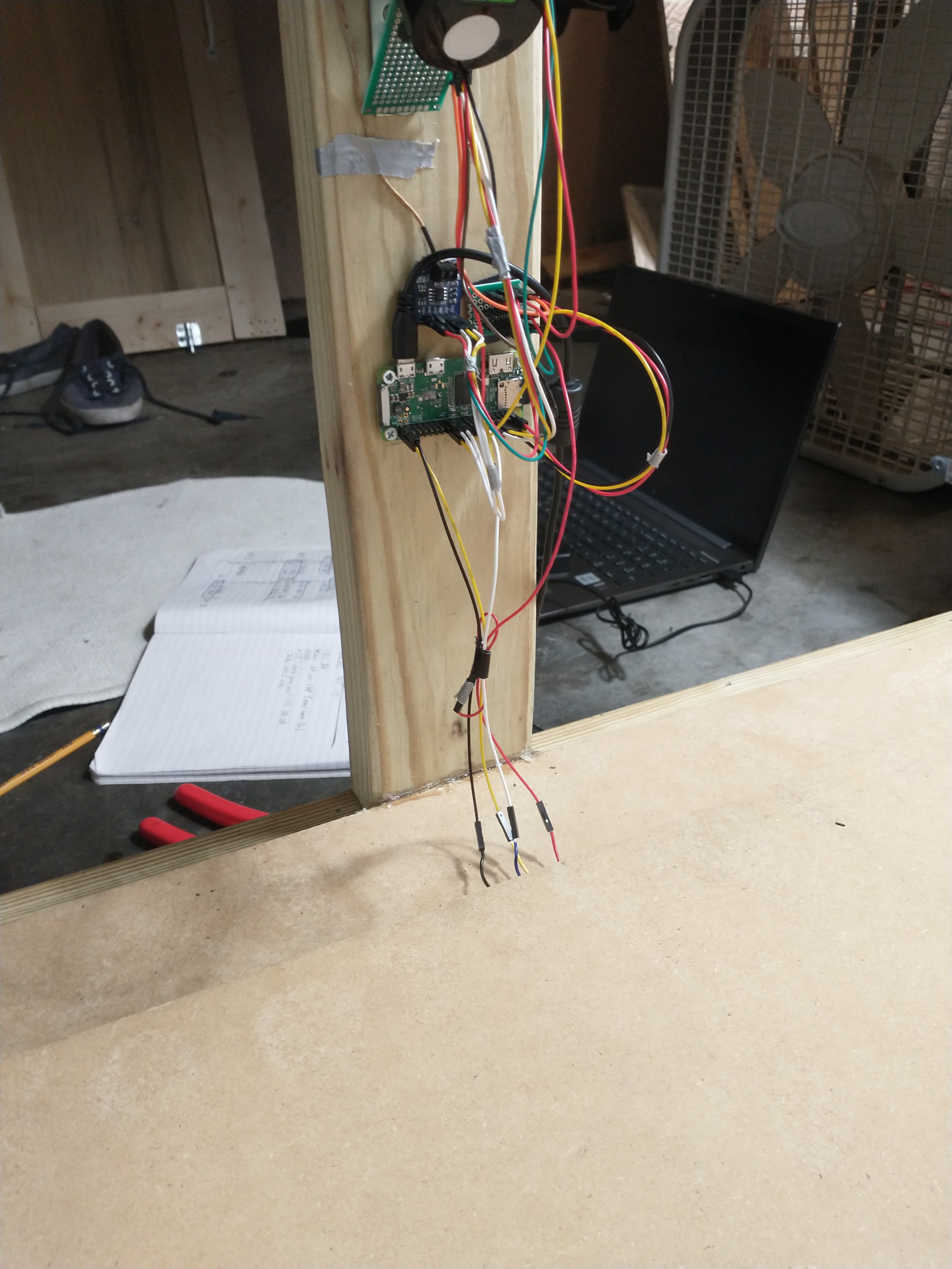
To communicate with the dimmer module it was necessary to increase the amount of GPIO available to my Raspberry PI, So I have attached an Arduino Mega2560 via usb for serial communication. (The usb cable is wrapping around out of the picture)
![]()
The raspberry pi will send serial commands to the Arduino Mega that correlate to each PID controller; e.g. "H 105", "I 200", "E 175", "CB 105", "CT 105". Each letter indicates which controller the command value is for; H = Humidifier, I = Intake Fan, E = Exhaust Fan, CB = Circulation Bottom Fan, CT = Circulation Top Fan. The value corresponds to how much current is being delivered to the actuator. I am considering also migrating all 4 of the sensors to the Arduino Mega as well, in hindsight I should have been using the raspberry pi to command the Arduino Mega for it's more expansive GPIO capabilities from the start. I will make another breakout board for the Arduino Mega, this way all of the sensors and AC phase controllers will be neatly on one board. I will leave the relay control tied directly to the Raspberry Pi, I've already built that and that feels like an appropriate use of the Raspberry Pi's GPIO.
Adding the AC Phase Controller to the Relay
![]()
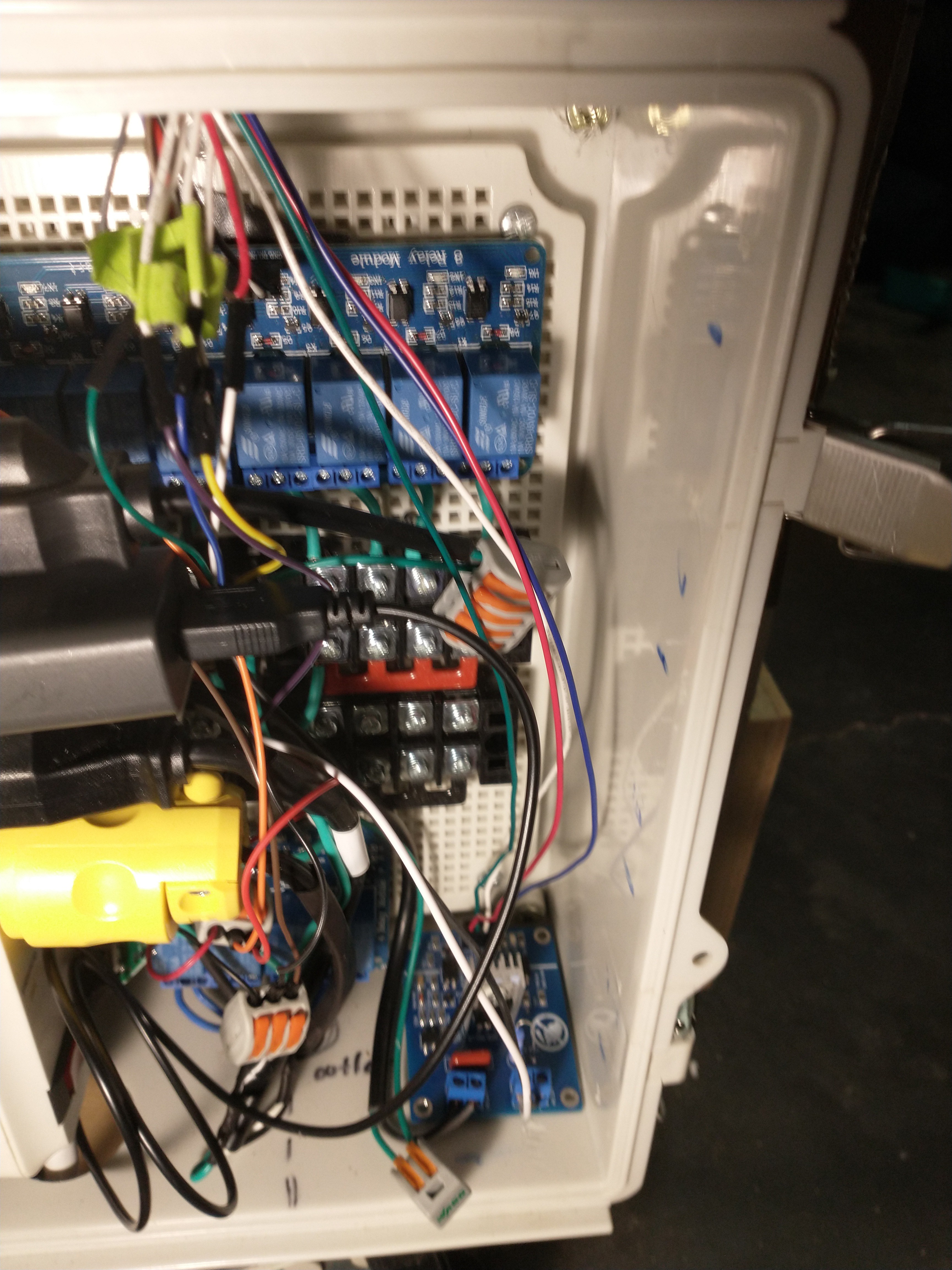
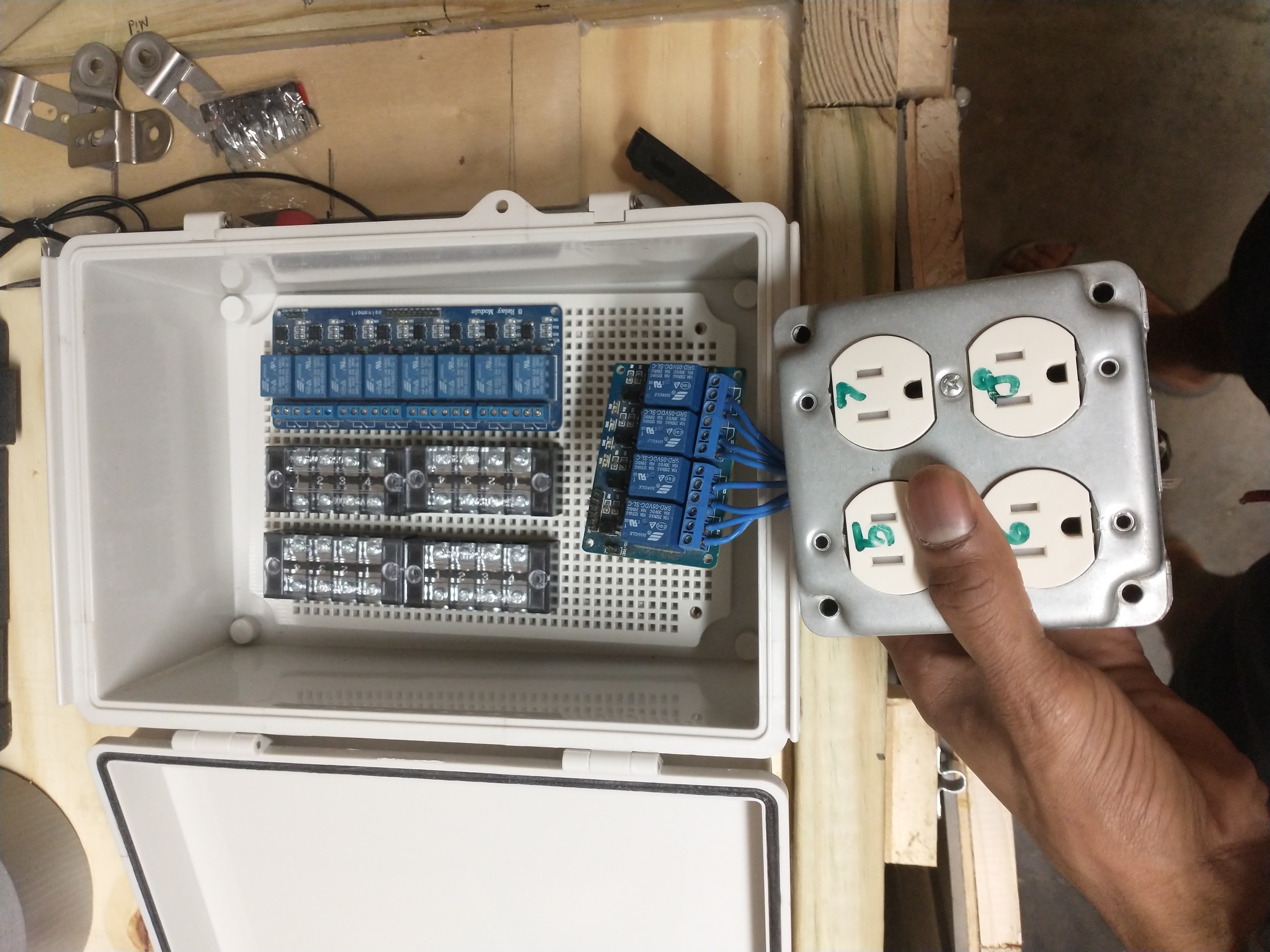
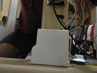
The blue board in the bottom right corner of the relay box is the controller I'm using for now. If you look at the right side of the box you'll see little blue markings where I was planning on including more of these modules. However I found a better option, an 8 channel AC Dimmer module, which is a single board and much cheaper and space efficient (however, before I found this amazing board on amazon I already regrettably ordered 6 boards from Ebay that are taking forever to get here and I can't cancel ). The red, white, blue, and green wires leading to the board are the digital control and power wires connected to the Arduino Mega.
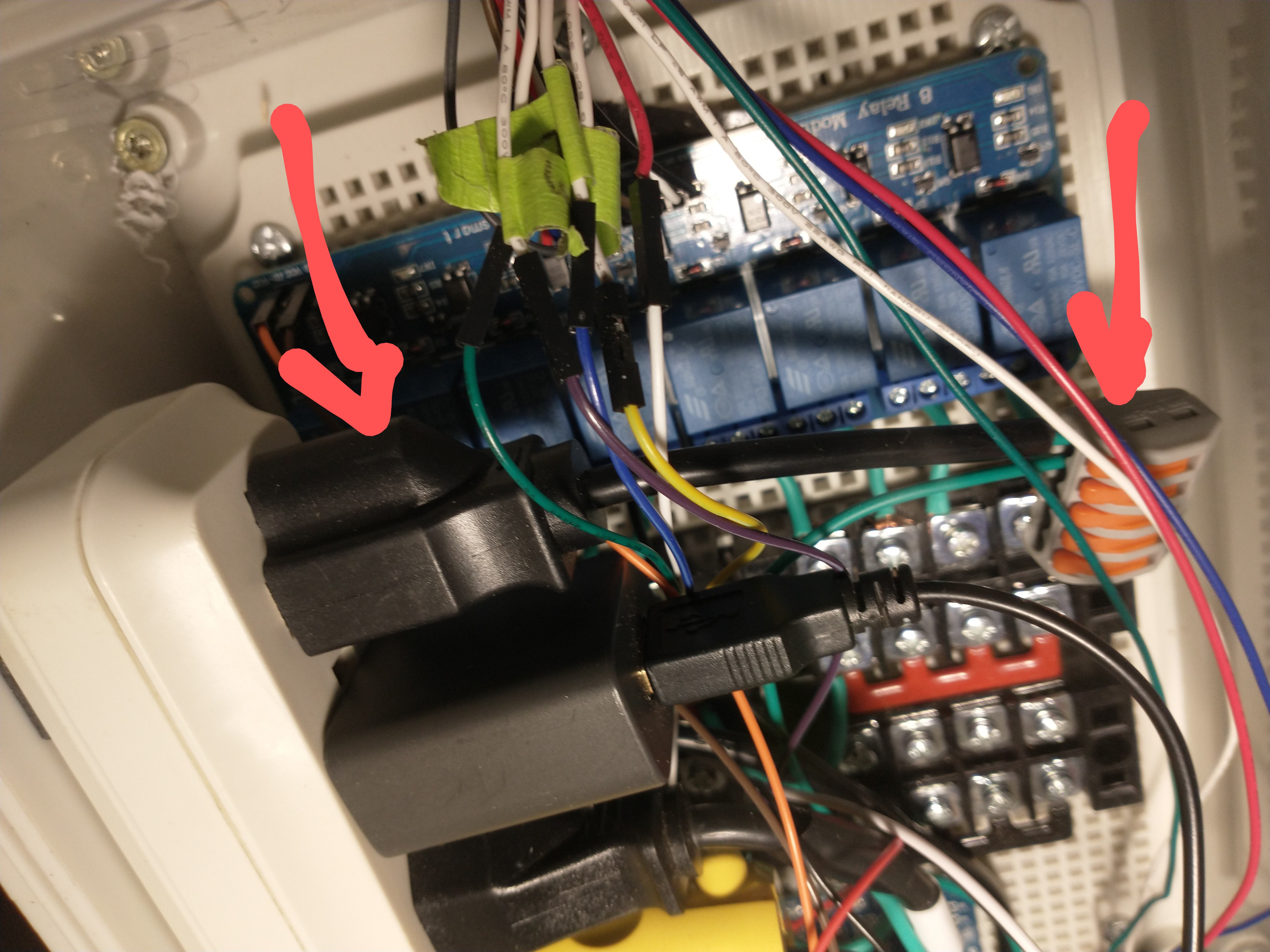
Because The Fan has a ground cable, I used a lever connector to rejoin it and then passed it to another 5 channel lever connector attached to ground. You can see in the below photo the outlet with only it's ground connected to a 5 channel lever connector. I will attach the ground of any other AC phase controlled device to this grounding level connector as well.
![]()
The Humidifier Port
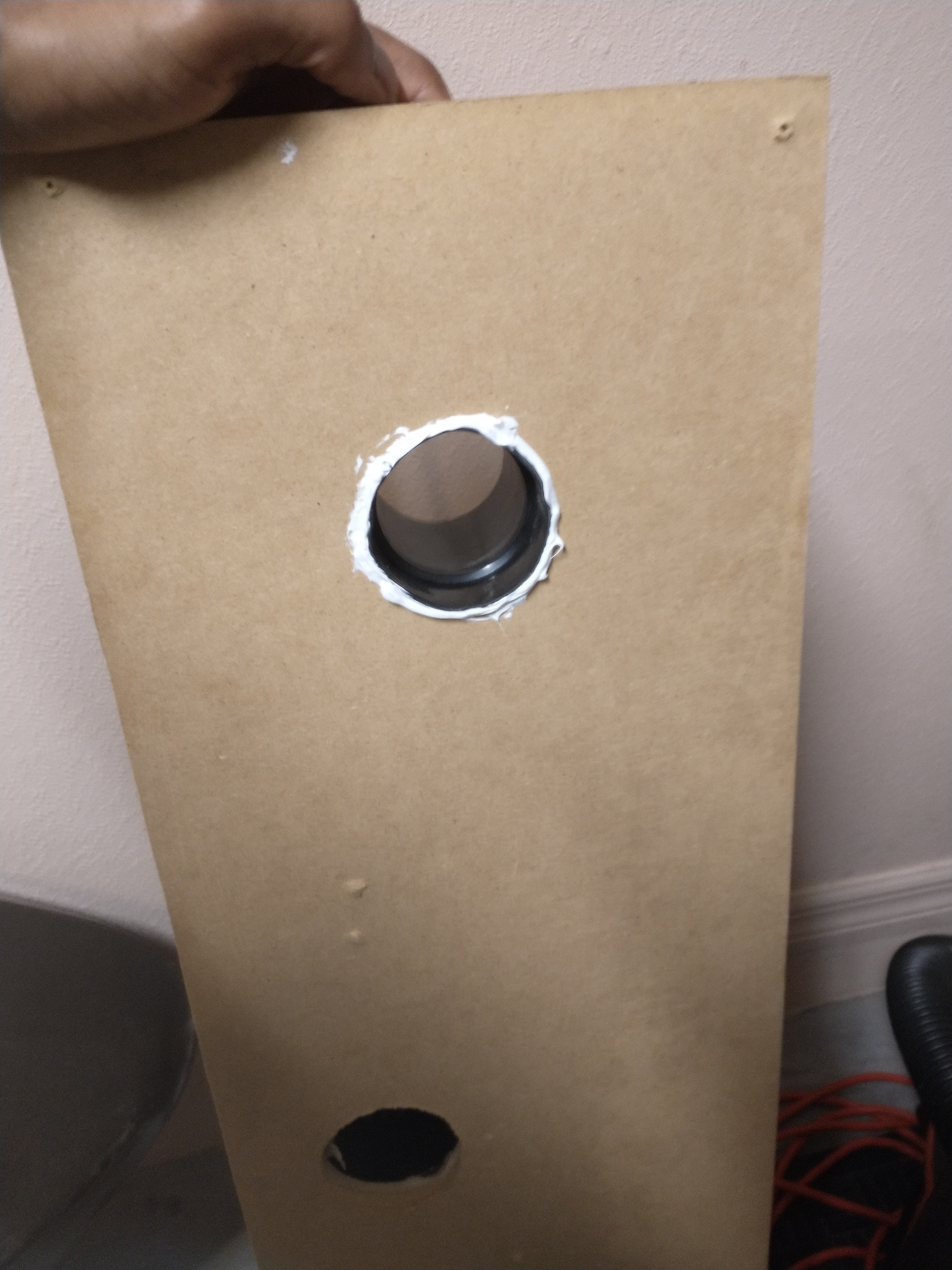
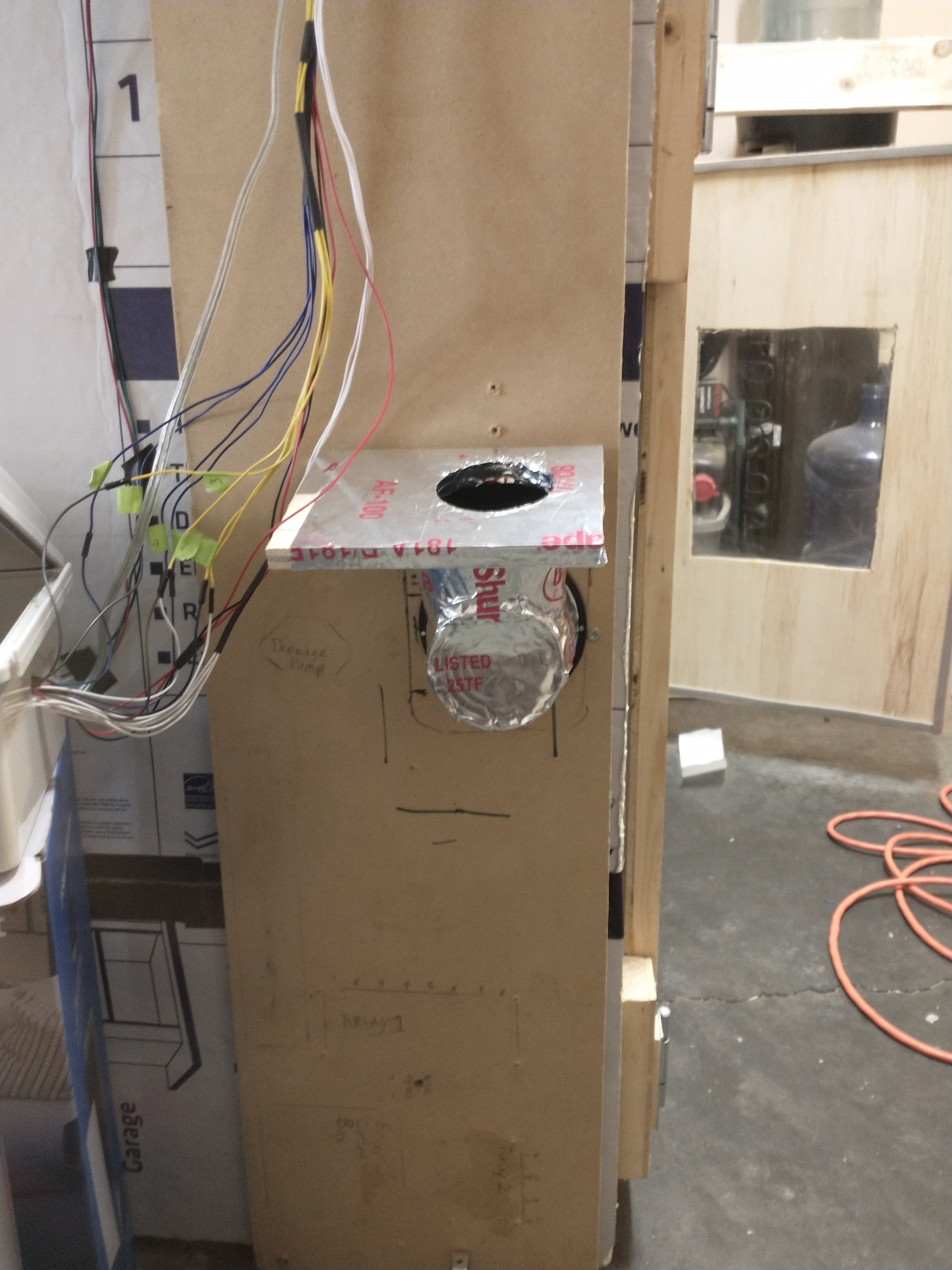
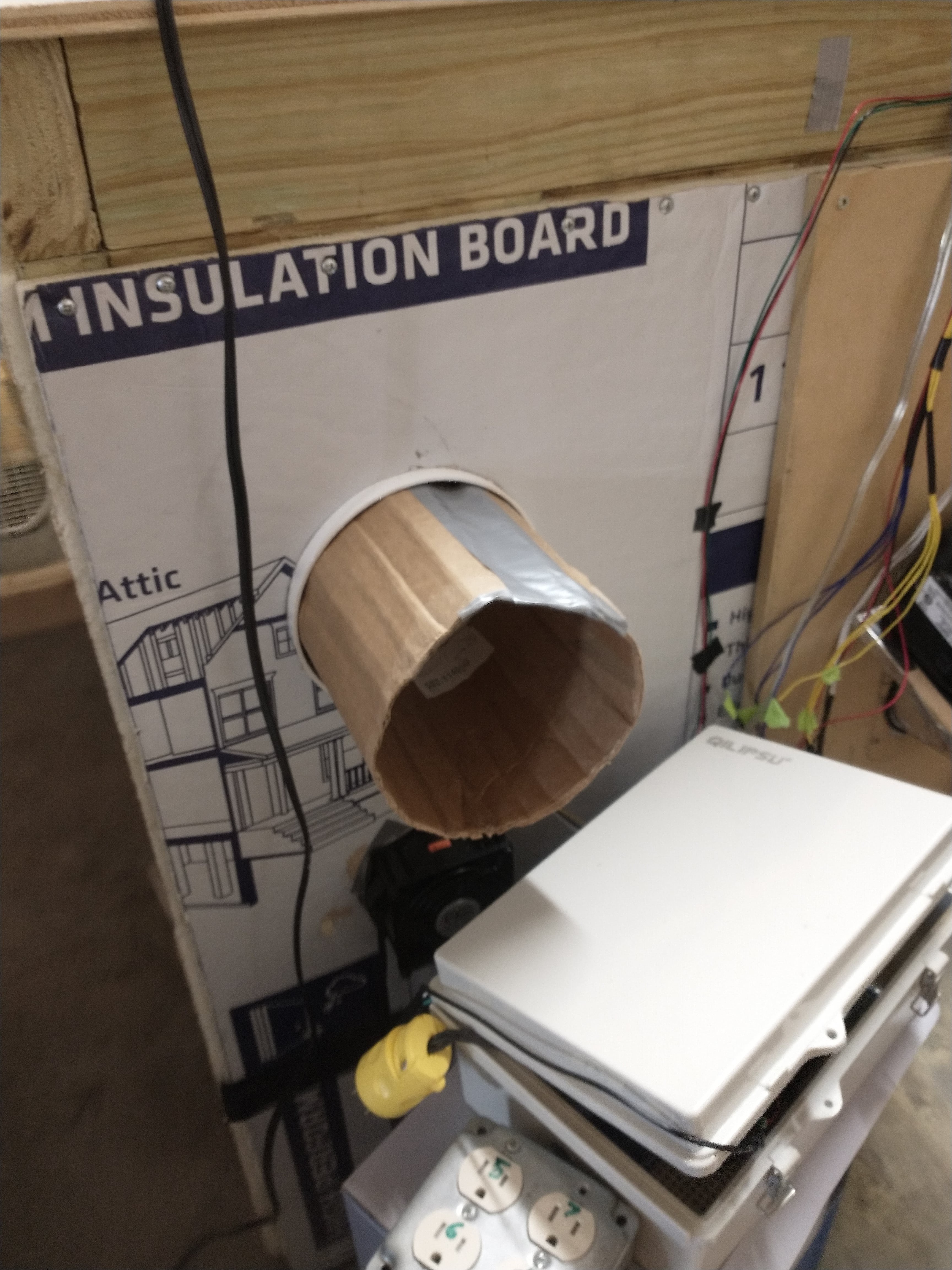
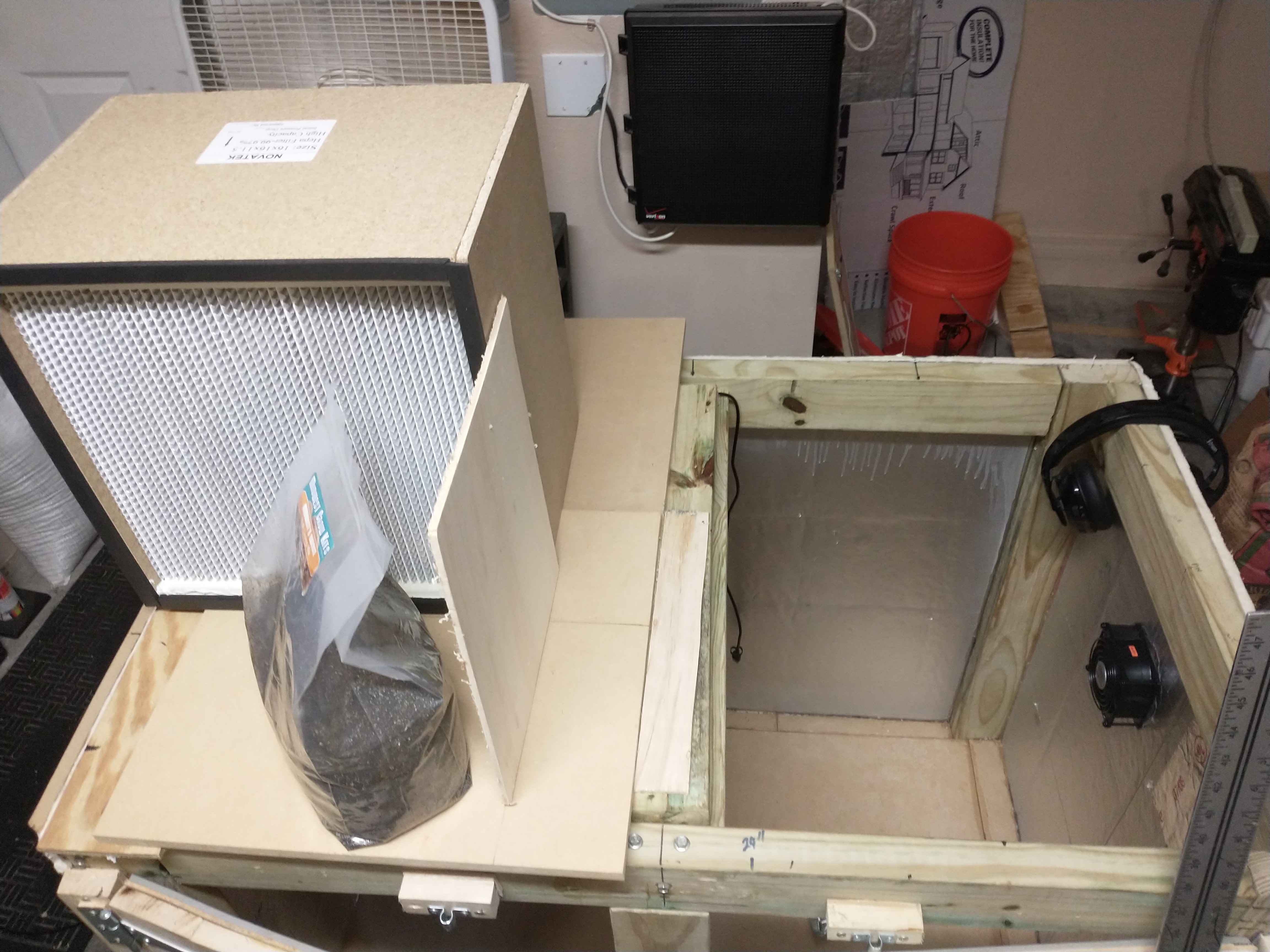
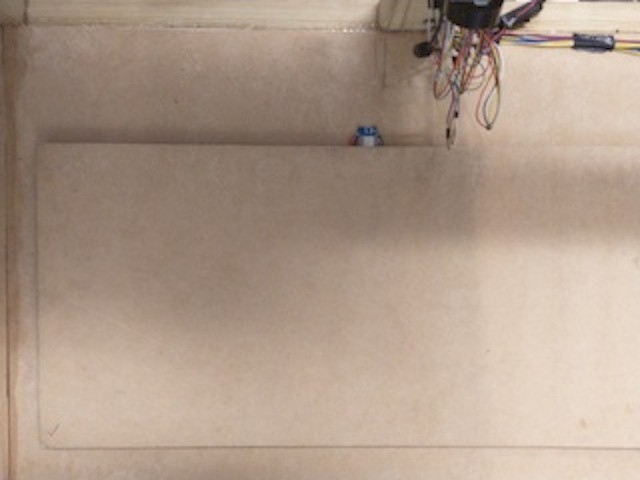
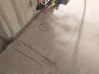
Fashioning a port for the Humidifier was simple enough, I cut a hole with my largest circular saw drill bit and then widened it a little bit more to fit a shop vacuum attachment. The humidifier hose is a shop vac hose that is secured to the bucket lid and clips on/off to the vacuum attachment. This way the humidifier can be attached or detached when needed. You can see the steps I took to creating the port below.
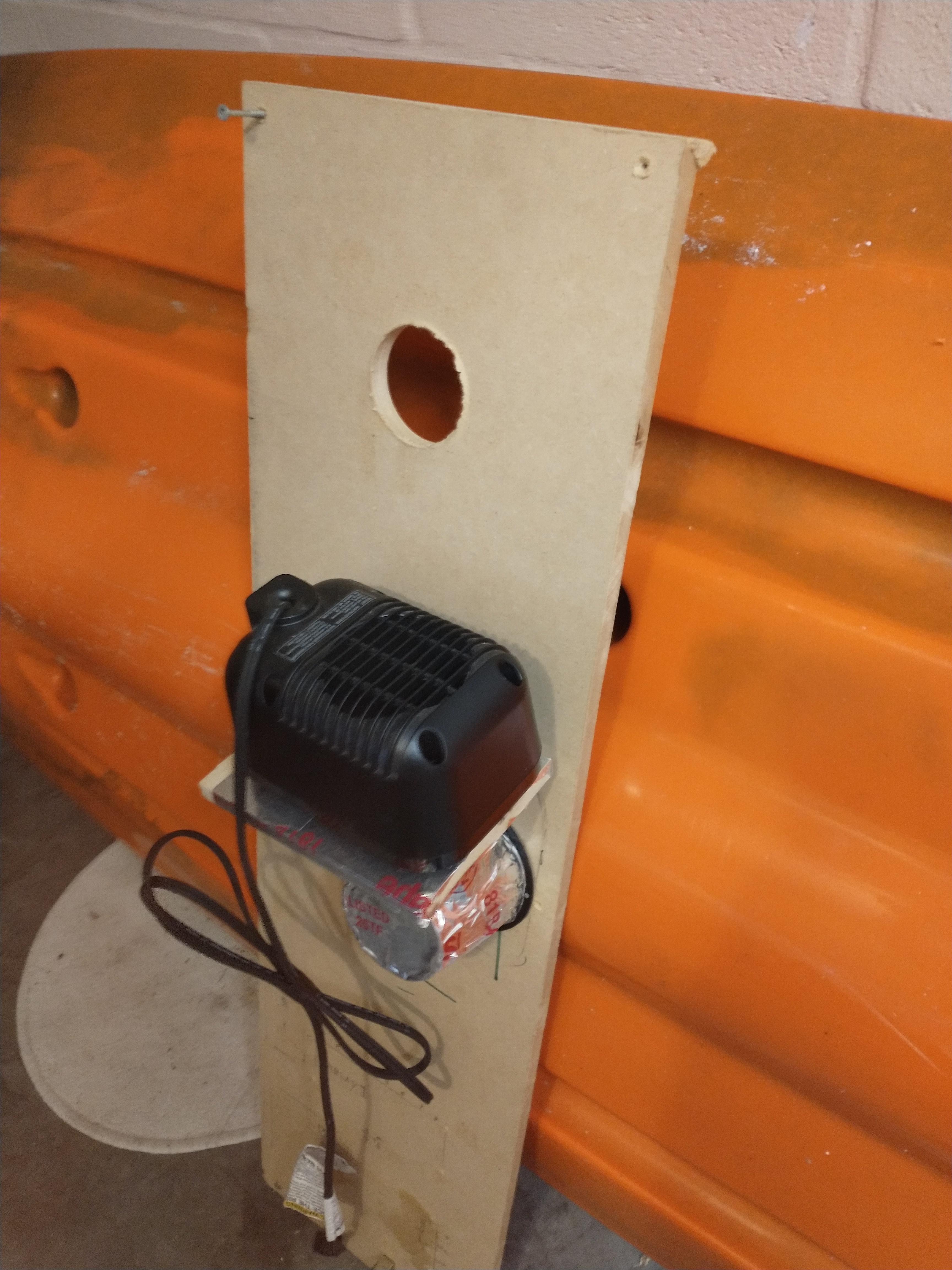
Here I've removed the wooden relay panel from the side of the mycobox to drill a hole for the humidifier port above the heater.
![]()
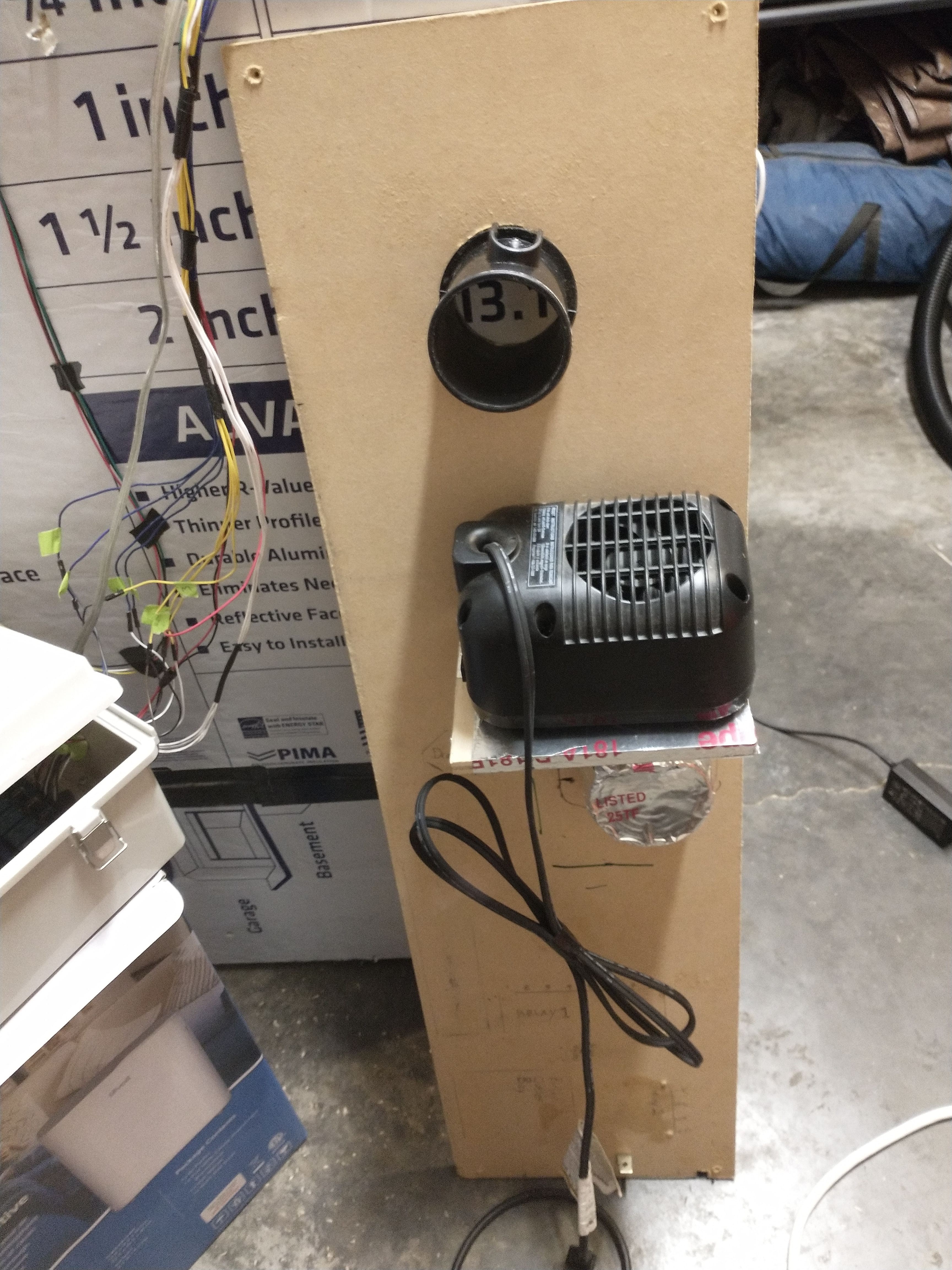
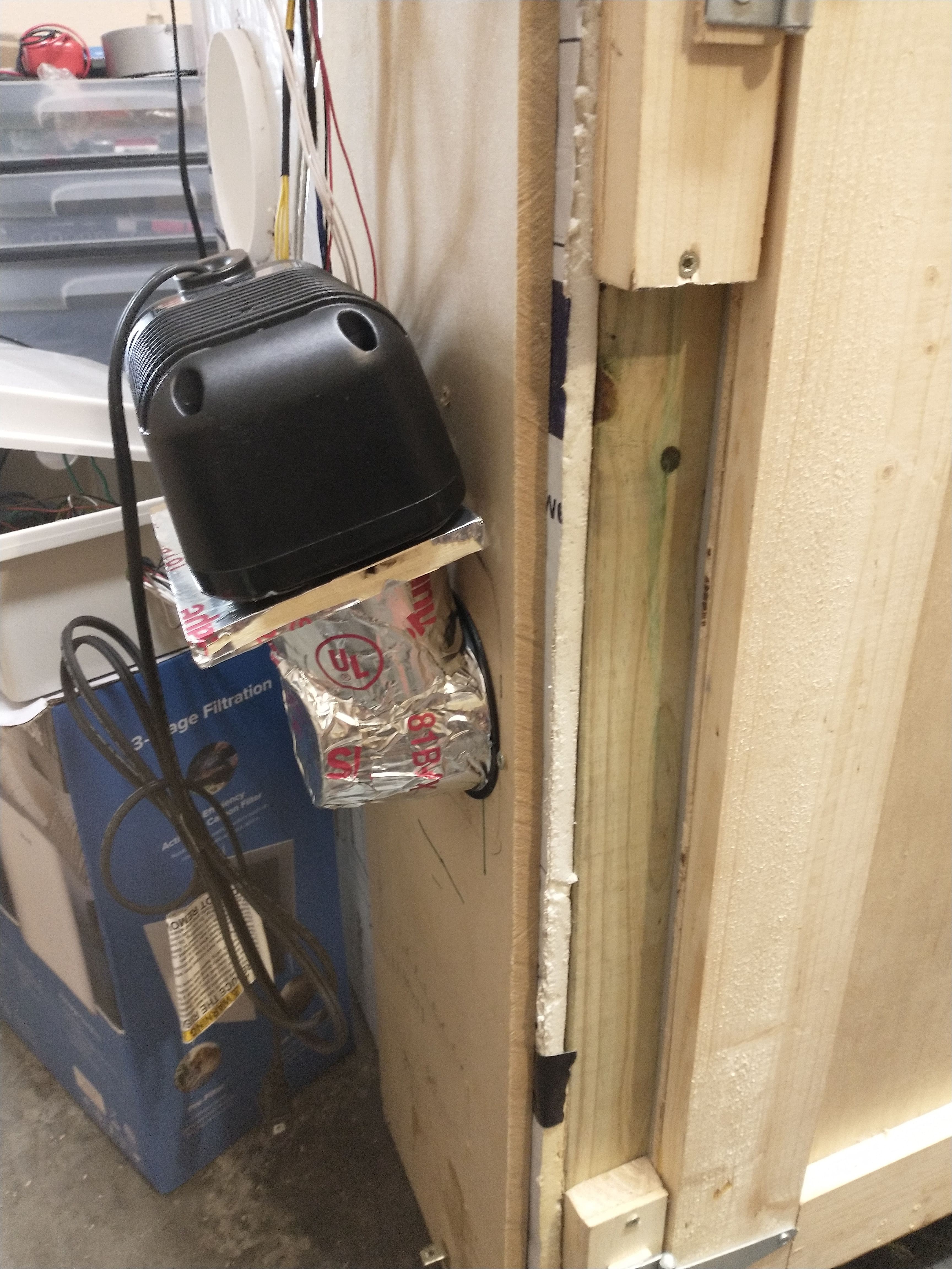
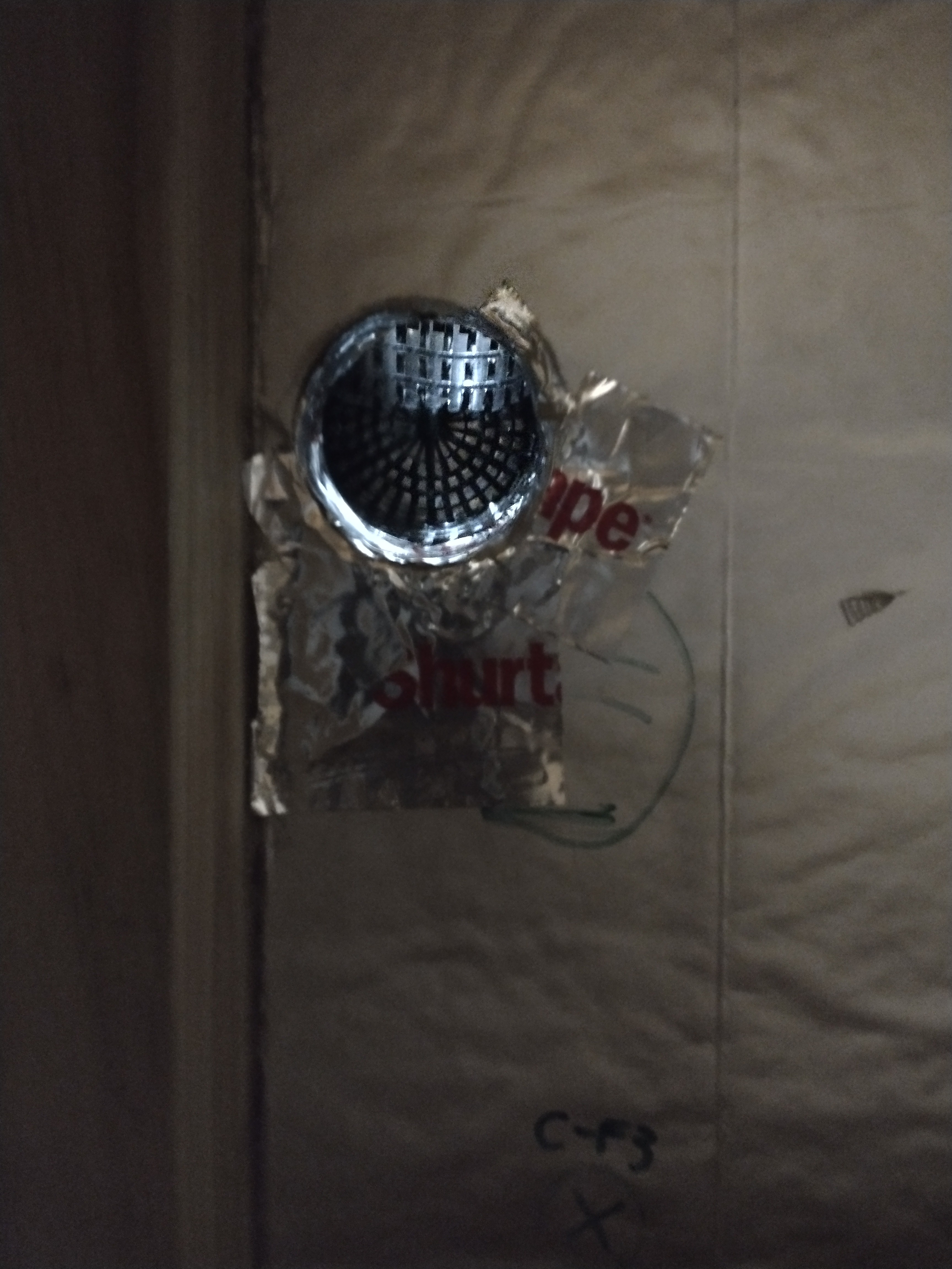
I expanded the hole a little bit more with a hand saw and then jammed this shop vac attachment into the hole to make a port. I sealed it with silicone caulk for a tight seal.
![]()
![]()
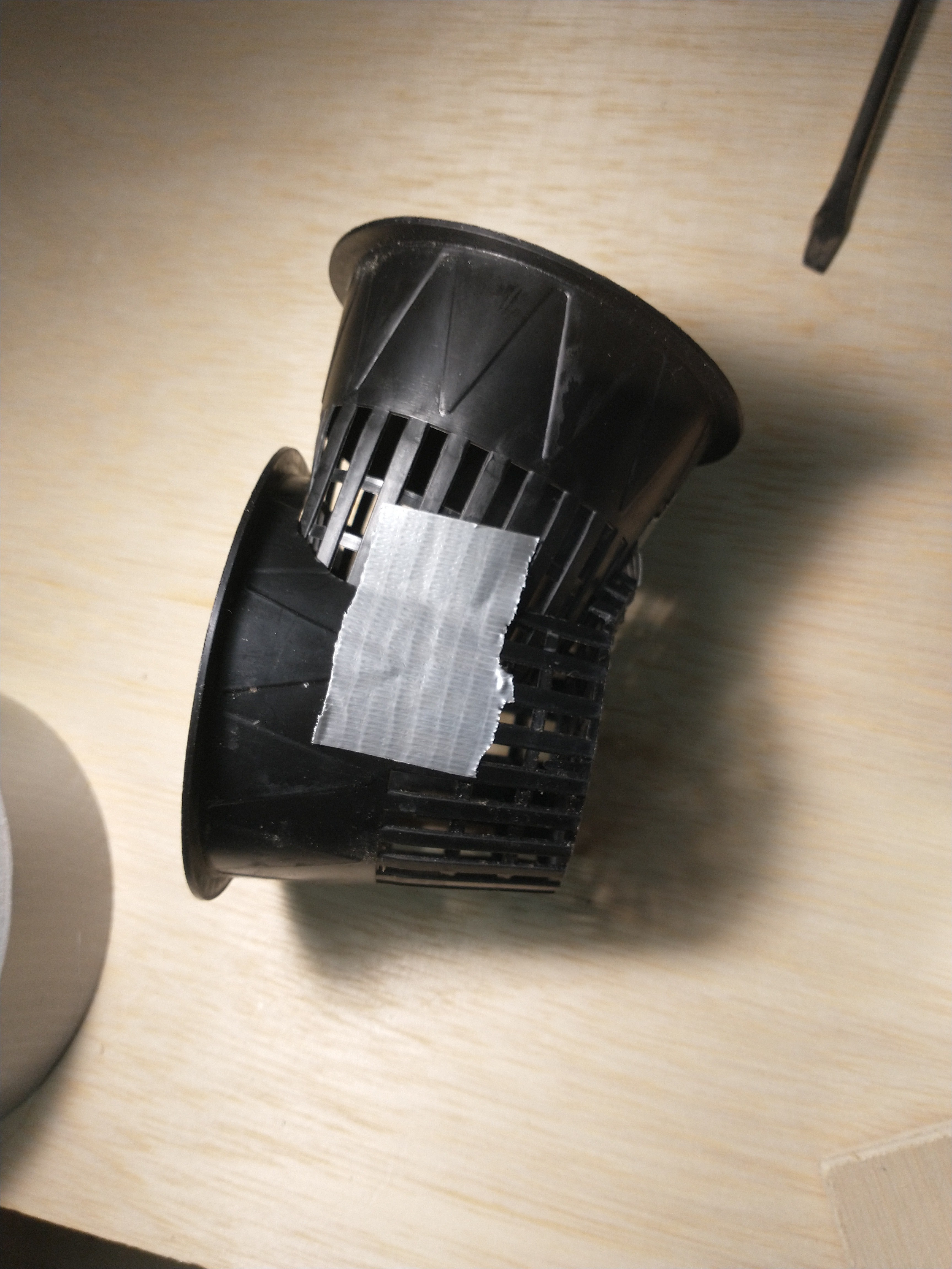
Making a Humidifier from a 5 Gallon Home Depot Bucket
![]()
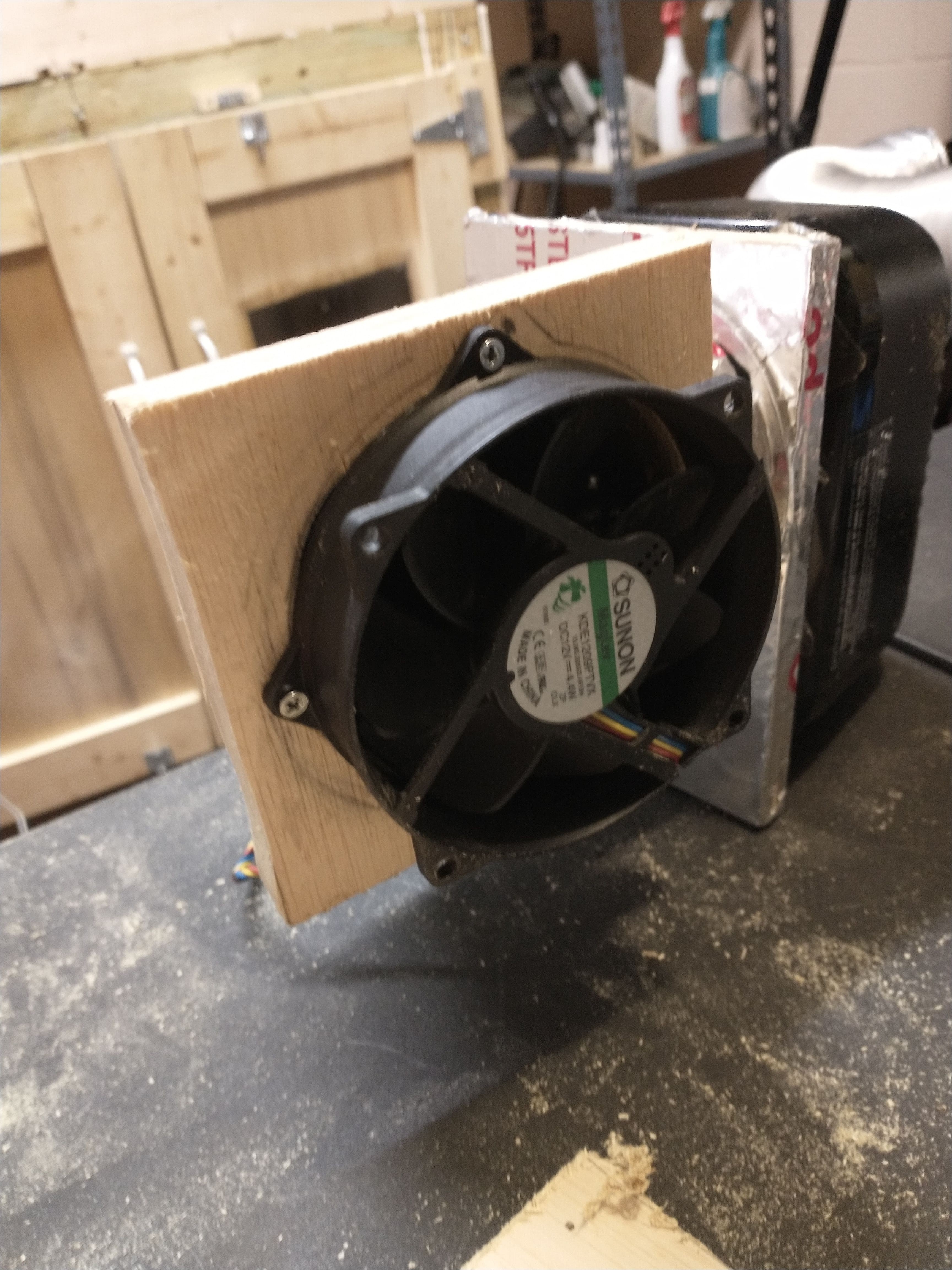
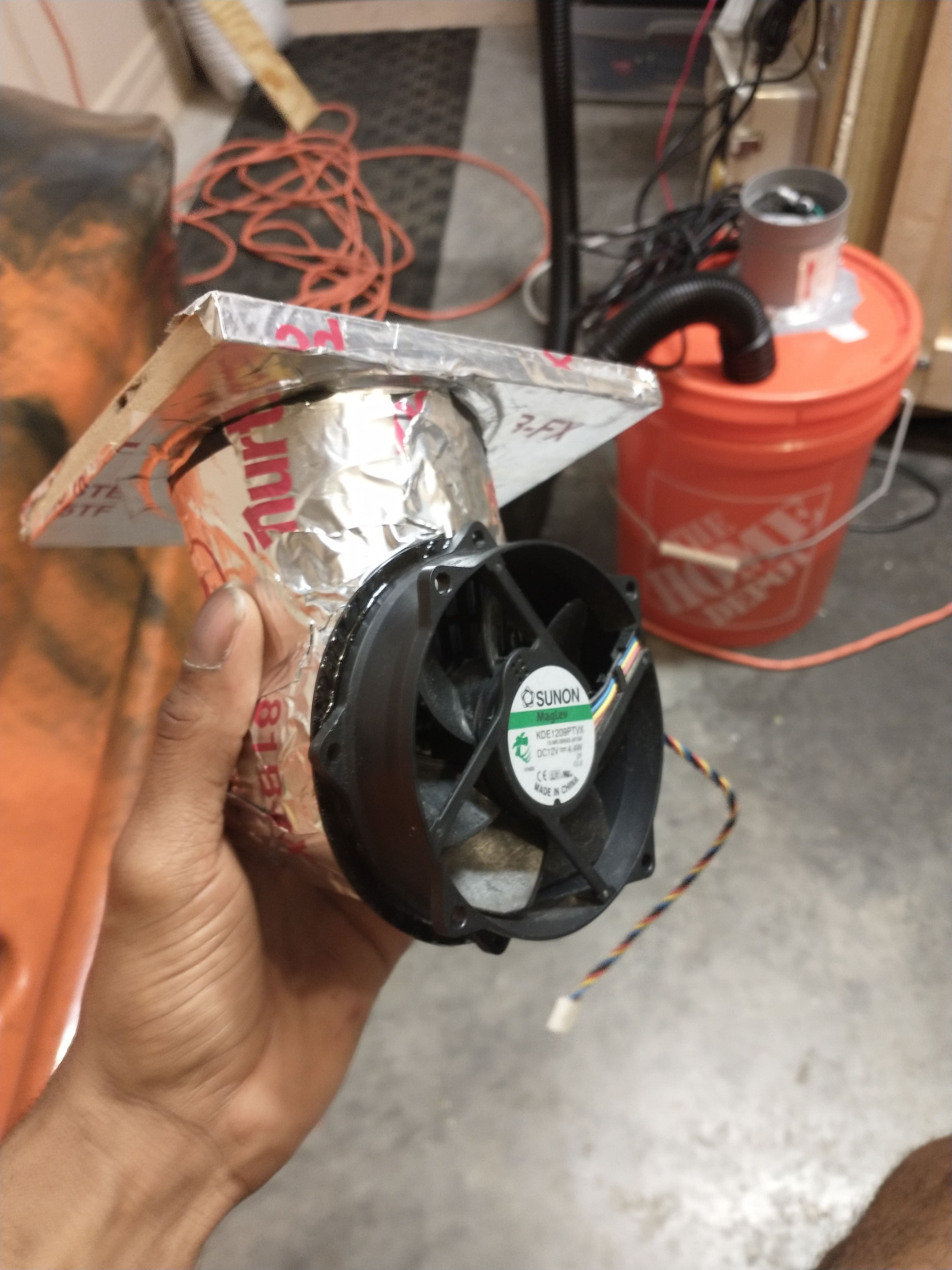
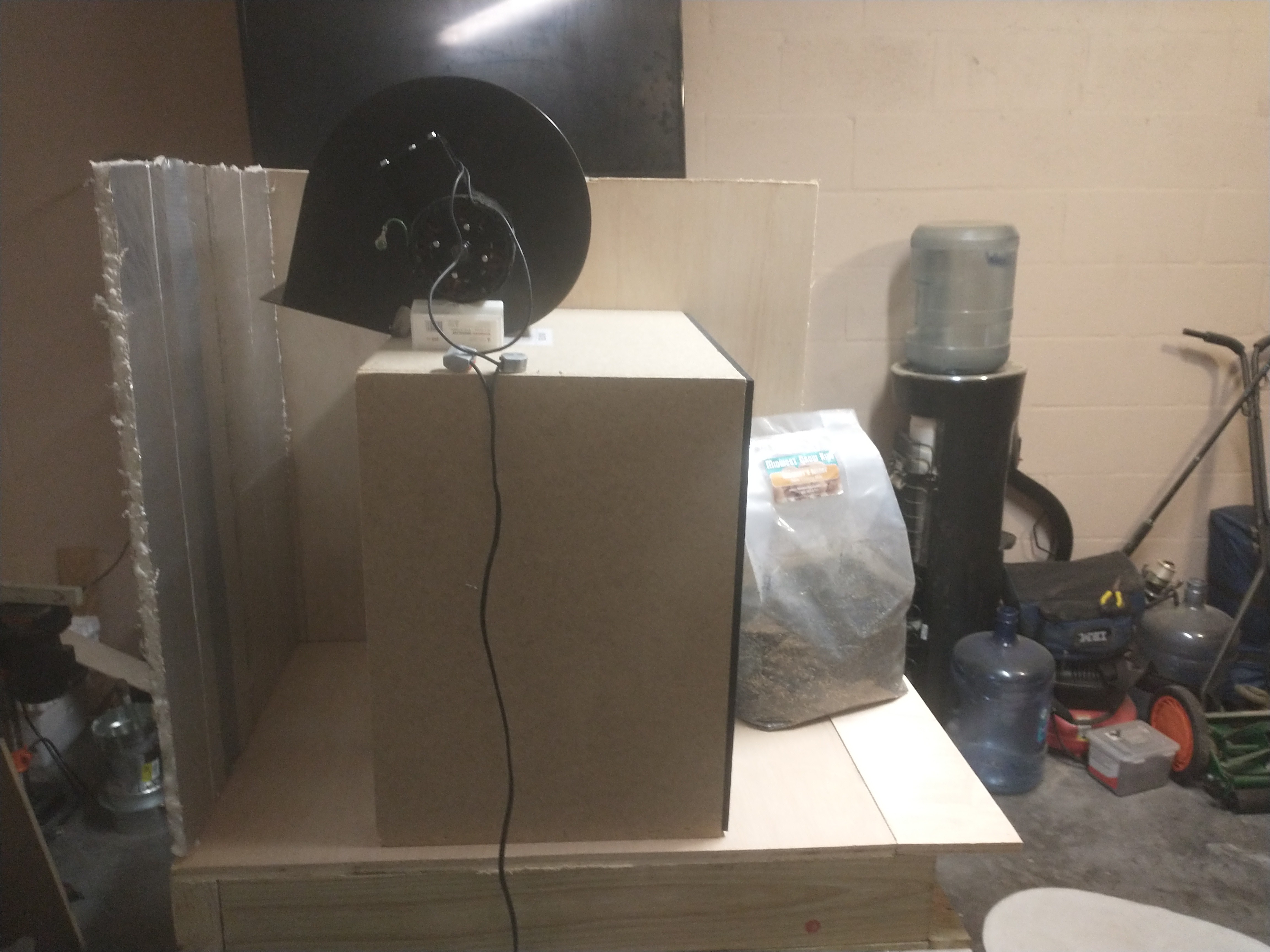
You can see I've simply attached a booster fan pointing downwards to the lid of the bucket with a very secure mix of duct-tape and foil-tape 😅, this is the fan controlled by the AC phase controller. The shop vac hose fit like it was designed to snap into the lid after I cut a whole slightly smaller than the hose's diameter. And there is a tiny hole for the power cable to the mister leading out of the bucket (humidifier) as well. Soon I'll also be adding a water level sensor to the bucket, which will alert the user that the bucket needs more water; this is to protect the humidifier from damage.
There are a few other programatic safety thresholds in place for the humidifier, such as cutting off the mister or reducing its power when permissible to save power and prevent the mister from over heating.
![]()
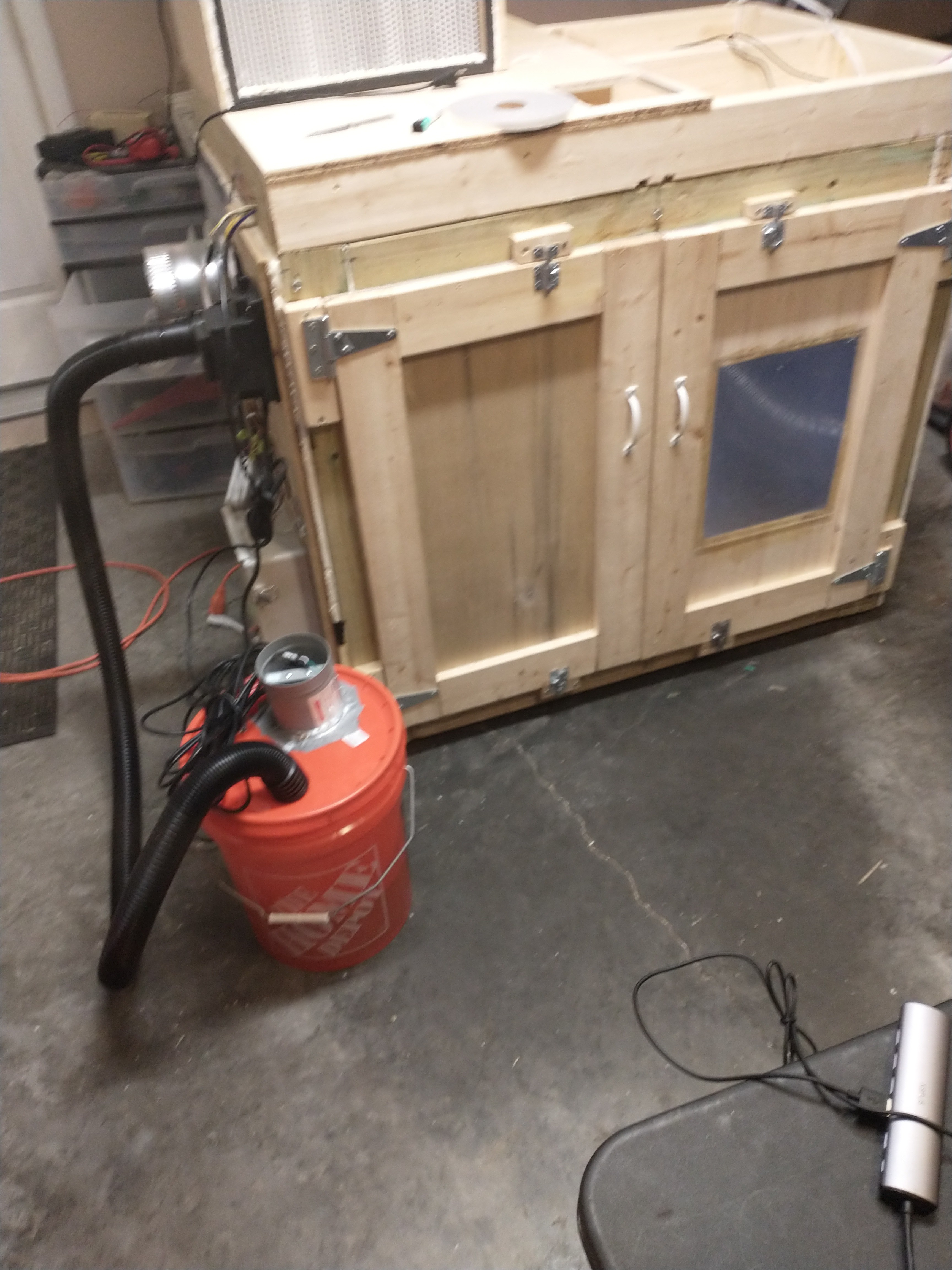
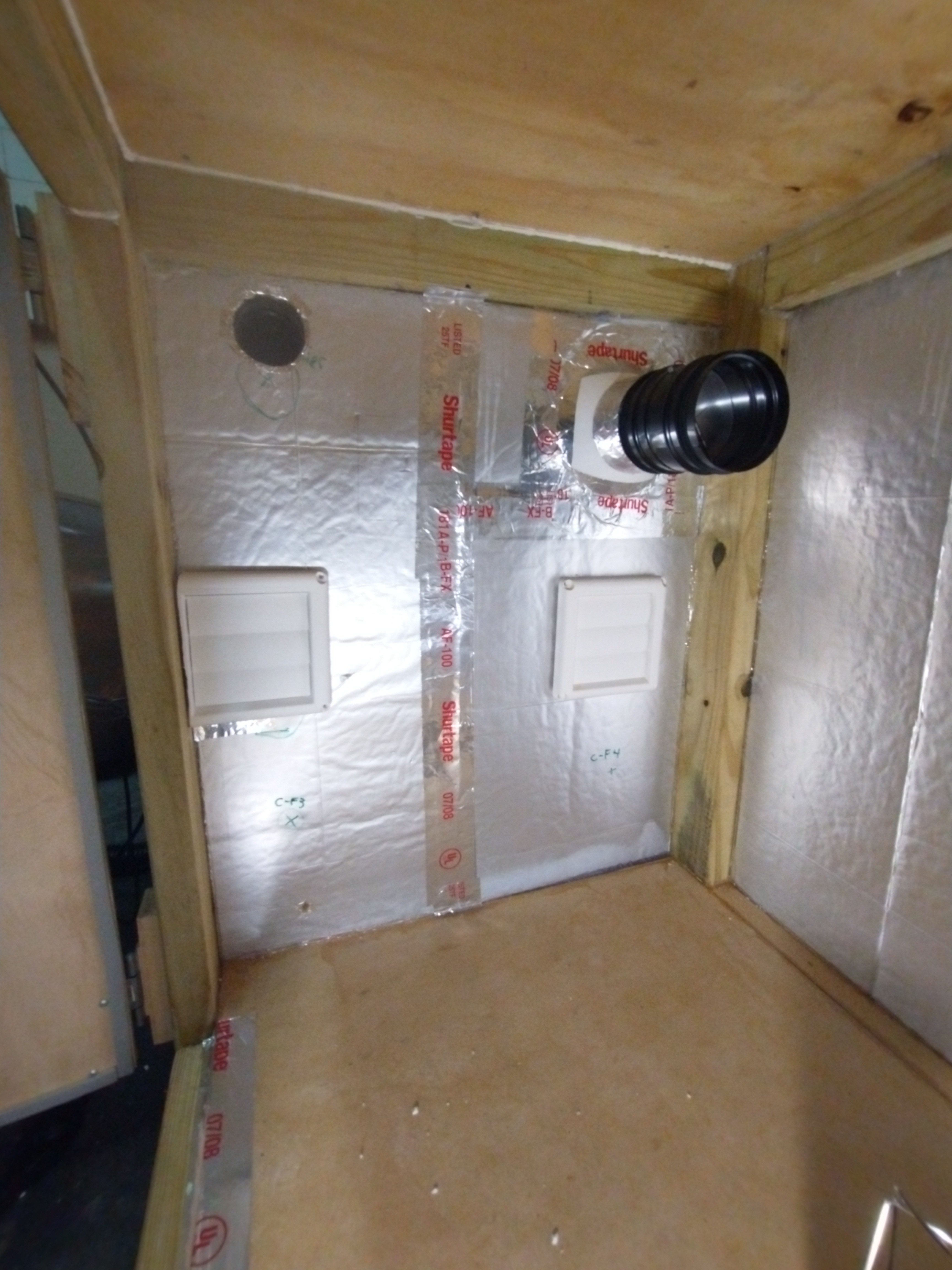
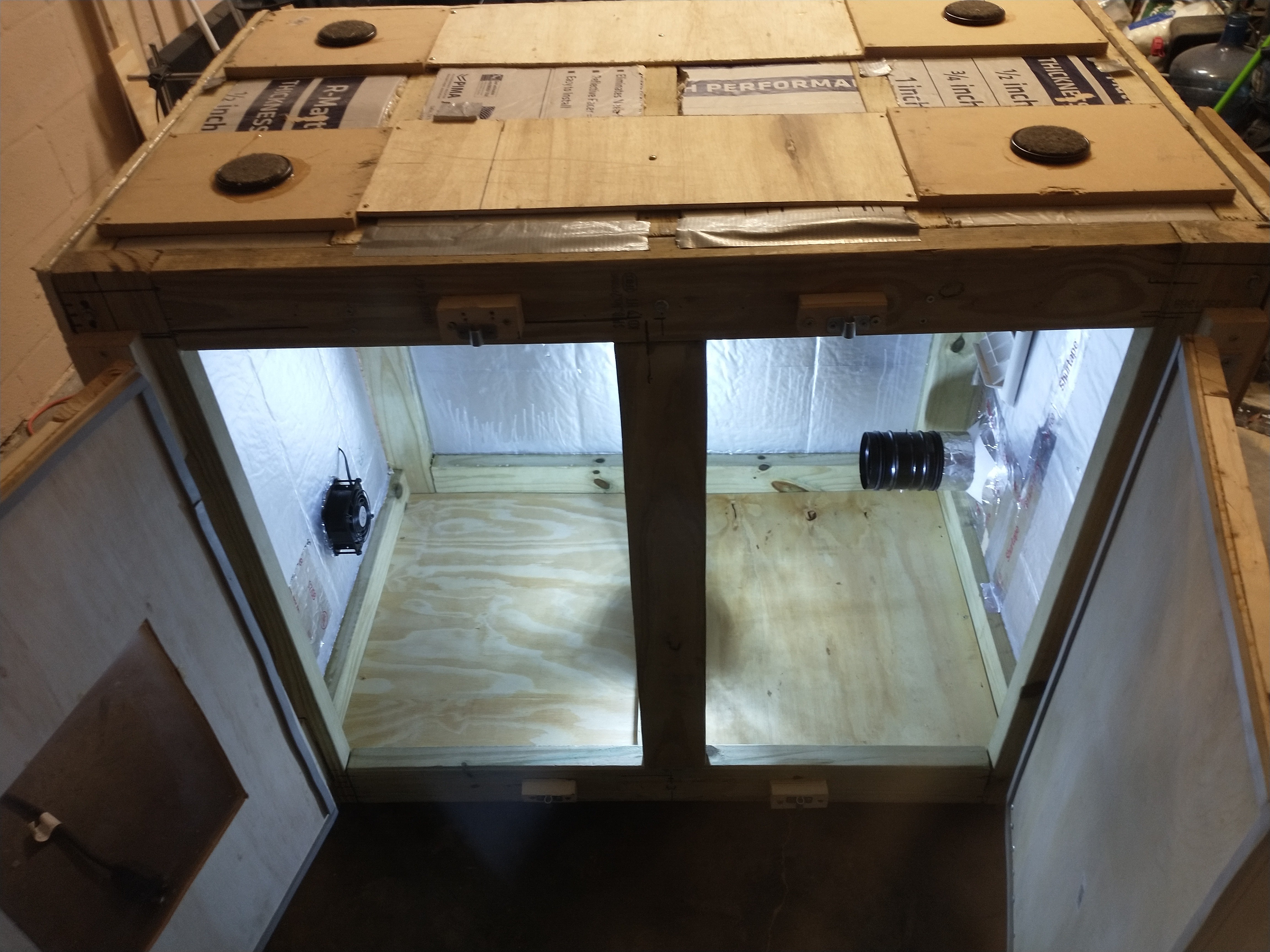
Chamber View of the Running Humidifier
Next Steps:
The Humidifier hardware and circuit is set up and ready to be controlled by a PID controller, and in order to tune the controller correctly I will be running step tests, and bump tests today to form a First Order Plus Dead Time model that closely models the dynamic process of increasing and decreasing humidity in the chamber. I have attached a few scans of my notes on how I'm going about this modeling and design process. This website offers a very good breakdown, with details, of how to design and tune a custom PID controller, https://controlguru.com/.
-
New AC port and heater port
09/07/2021 at 16:58 • 0 commentsCreating a heater port out of plastic pots:
![]()
The MycoBox will often be filed with a thick mist to raise the relative humidity, however I don't want that mist soaking into the heater. To take steps to avoid that I made an L shaped port for the heater, so that it's positioned out of the MycoBox. Mist gets everywhere when you start to blow it around, but hopefully the positioning of this port will reduce exposure; at least when the circulation fans are off. I created the L by cutting the bottom off of one pot and taping it onto another.
![]()
This is the board that the heater is mounted to with mounting tape, and the pot is nailed into place onto this board.
![]()
here is a photo of the pots covered in Shurtape, which is aluminum foil ducting tape, which converts these simple pots into a functional ducting port now. I created this with pots because I already had these pots laying around and its pretty easy to create a sturdy port this way.
To get the nails in place I heated a nail and pre-poked the holes. Then I pre-nailed the nails where the would go so that it would be easy to tap them into place when securing the port.
![]()
I added Shurtape along the port connection to keep it sealed
![]()
The below images shows how the heater will be mounted to the port
![]()
Here I've nailed the port to the side of the MycoBox using the same heated nail technique.
![]()
You can see how this port sticks out and up to try to keep the heater away from as much ambient fog as possible. The Heater will be face down on this port, and it blows down and into the MycoBox.
![]()
Here the heater is mounted face down to the port, the button is in the on position so the heater can be relay controlled.
![]()
Here is the port from inside the MycoBox...not the prettiest tape job but it's well sealed on the inside.
![]()
AC Vent Fan
The Final step to keeping the heater unit isolated from the internal climate of the box was adding a vent and vent fan to the heater. The Heater has a built in fan for blowing its heat outwards, however it does not have enough force to push open a vent. So I added an inline vent fan in front of the heater that will push open the vent and allow the heated air to pass into the chamber, yet when the heater and inline fan are off air and humidity from inside the chamber don't escape.
![]()
In the above photo you can see I'm using the same type of vent that is covering the intake fan. Below is a short video of the fan running when I first mounted it to the heater adapter.
Here are some images of the adapter from a few angels.
![]()
![]()
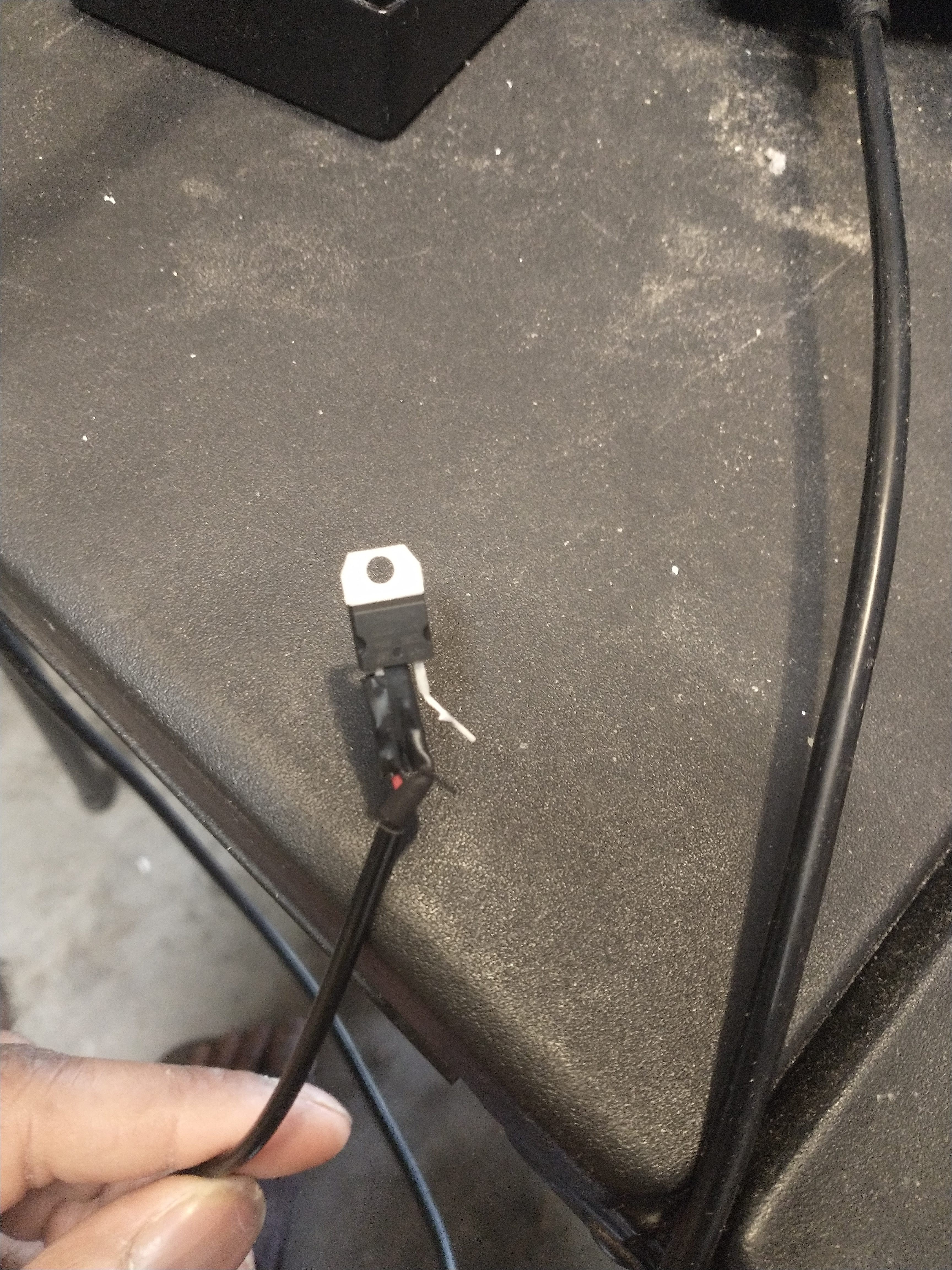
I slightly reduced the fan speed of this 12V fan by applying a voltage regulator to the power cable, which lowers it to about 8V; just enough to push the vent open and let the hot air in.
![]()
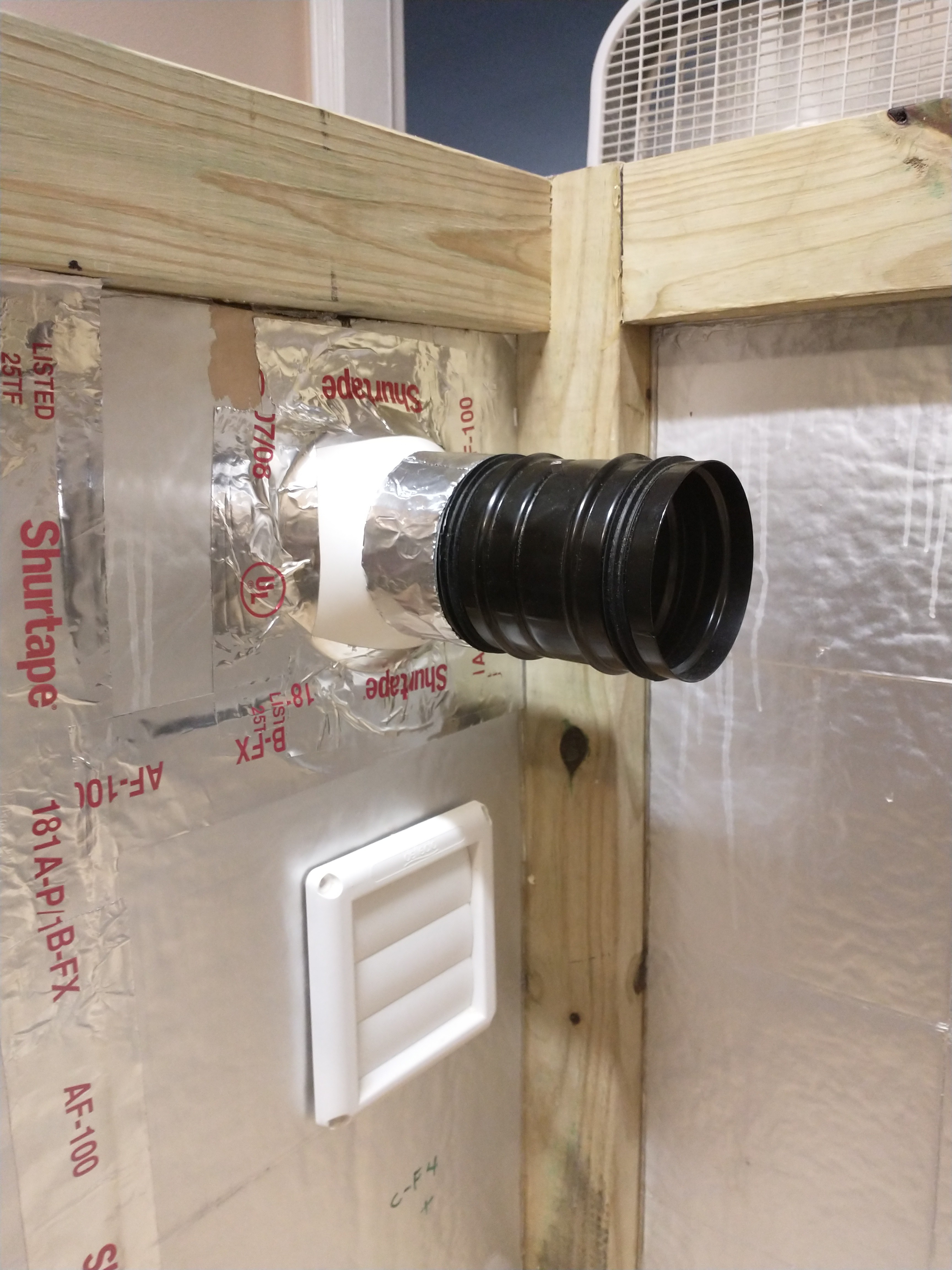
Modifying the AC port to be more secure:
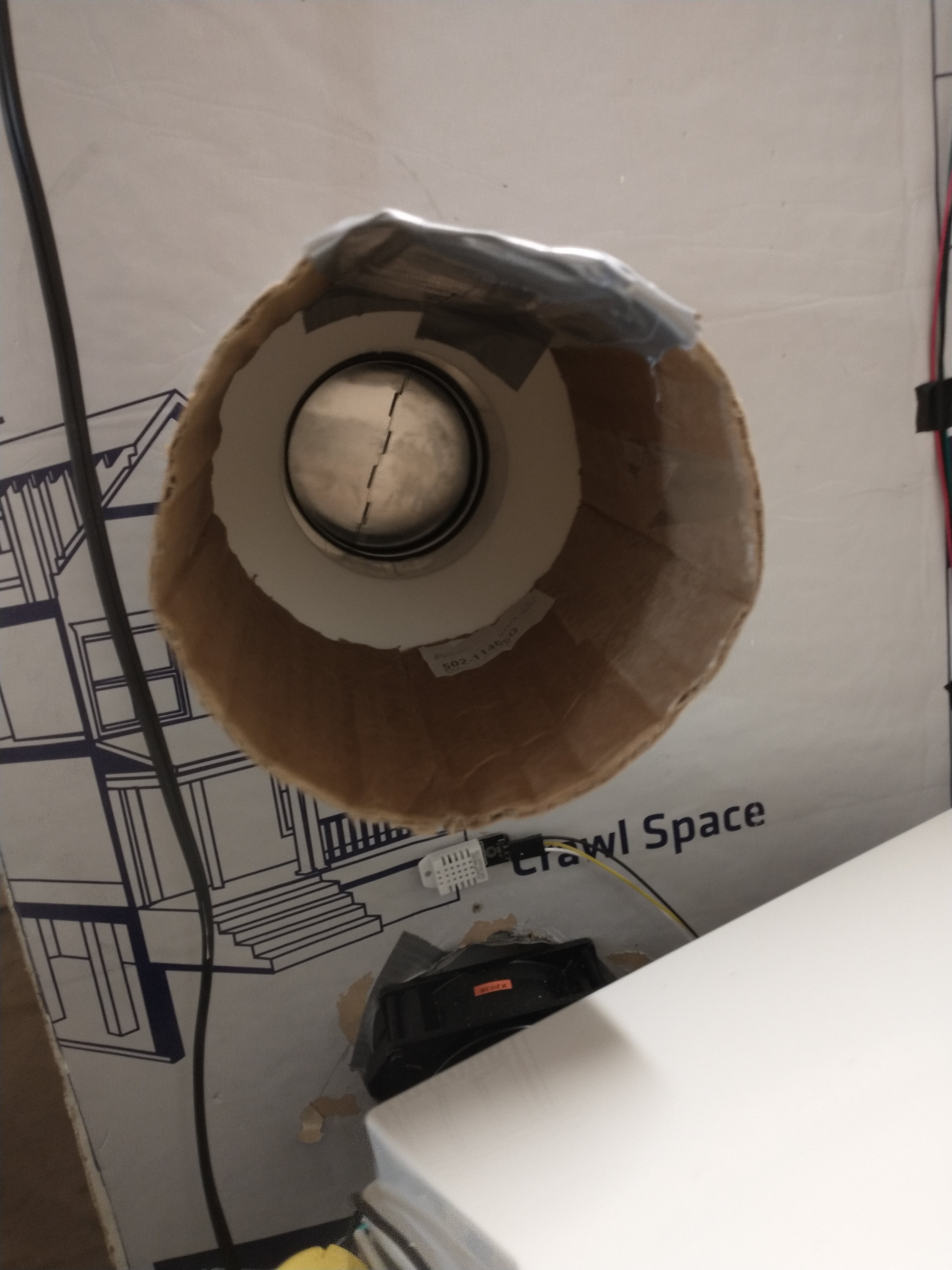
After switching out the AC port for the smaller plastic version that doesn't jut out as far into the MycoBox, the AC ducting has had a hard time connecting to the outside of the plastic port. So I added a cardboard inner connector between the plastic port and the old metal port, which easily connects to the AC ducting.
![]()
I fashioned a cardboard ring that matched the 6" inner diameter of the port, and then attached it with 3 pieces of mounting tape so that the cardboard adapter wont just slip out; it will have to be intentionally removed, it will not accidentally slip out.
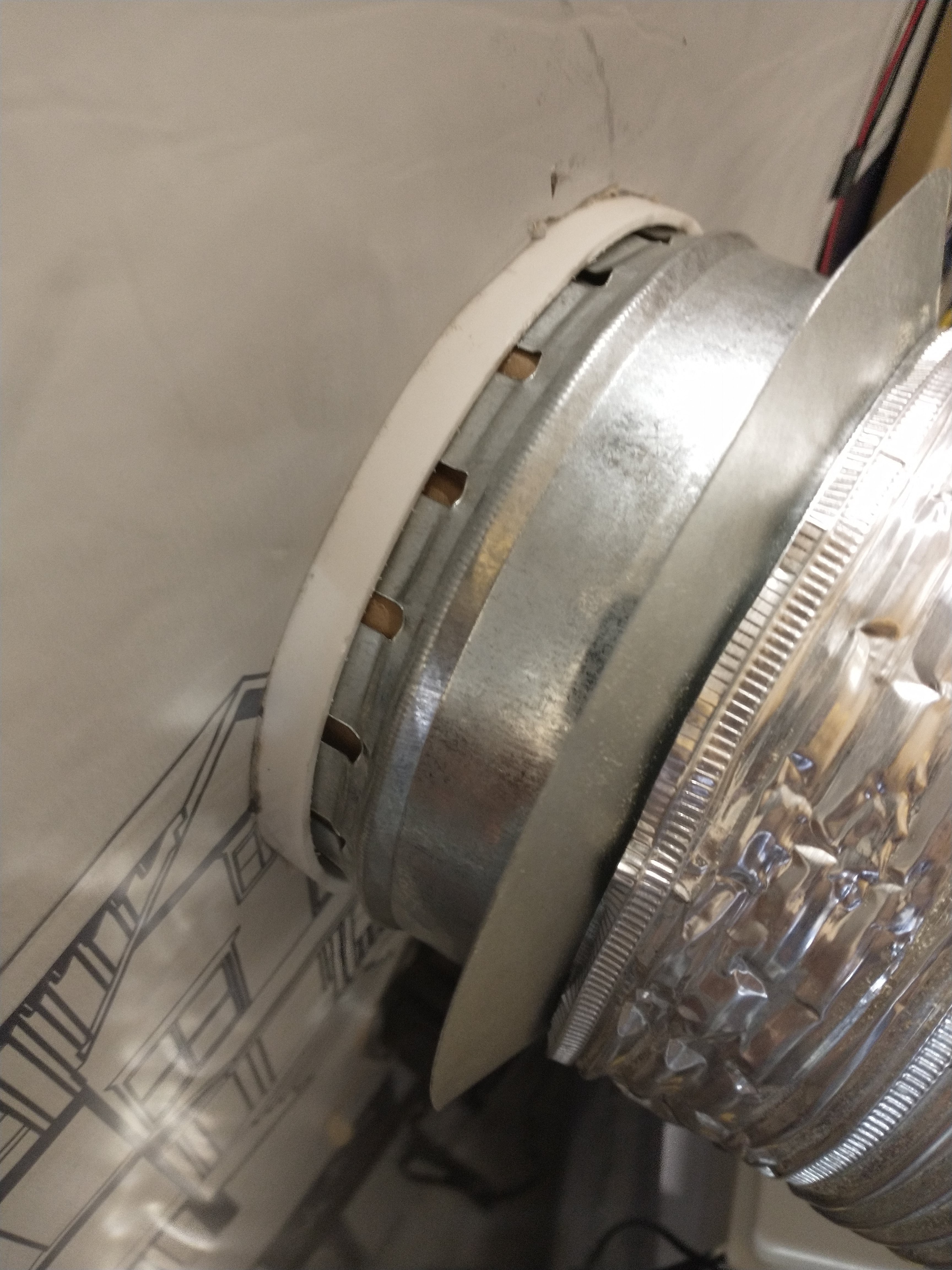
![]()
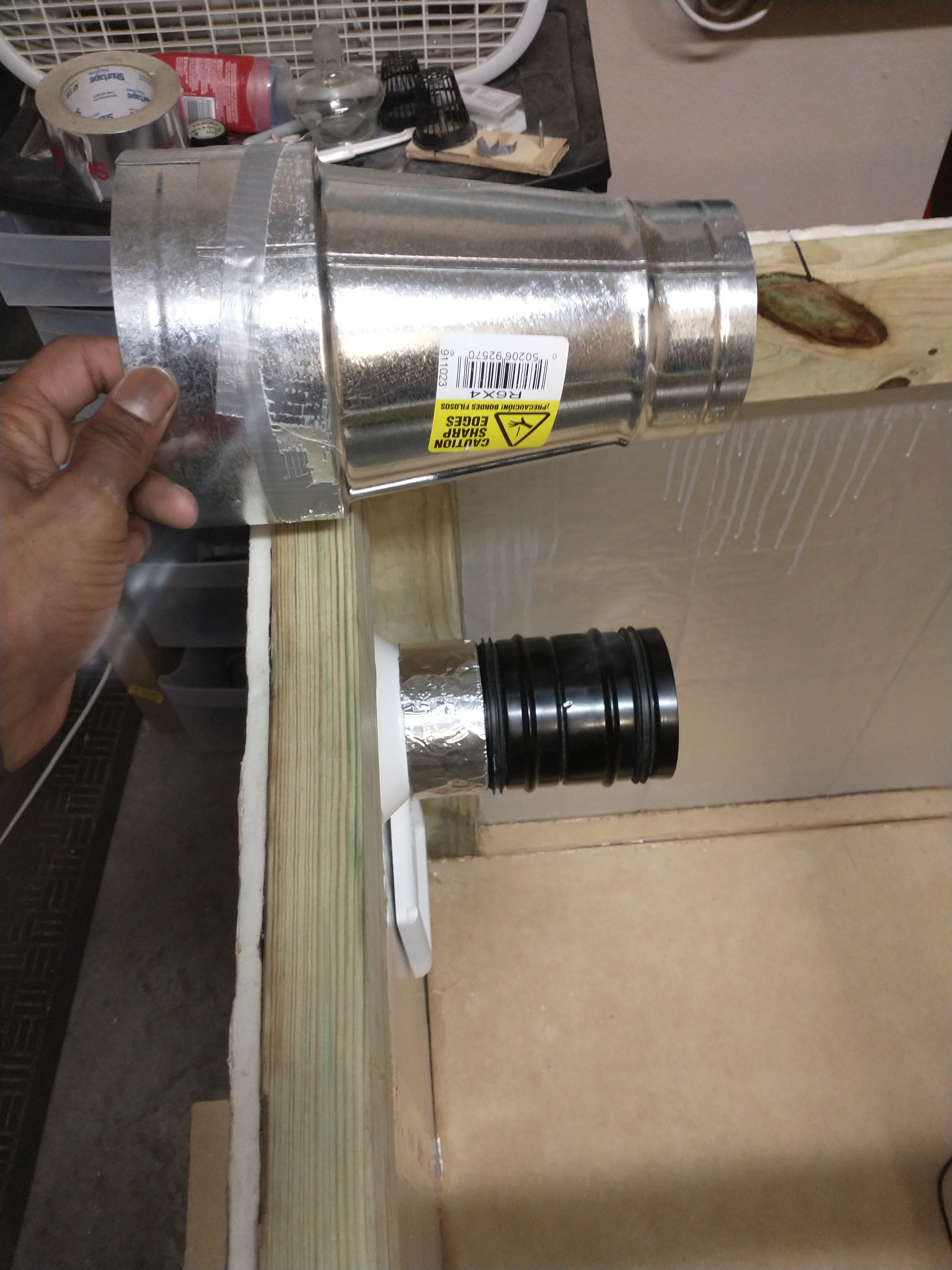
The metal port has foldable tongs that conveniently slip tightly between the plastic port and the cardboard adapter. The AC ducting then fits easily onto the large surface area of the metal port
![]()
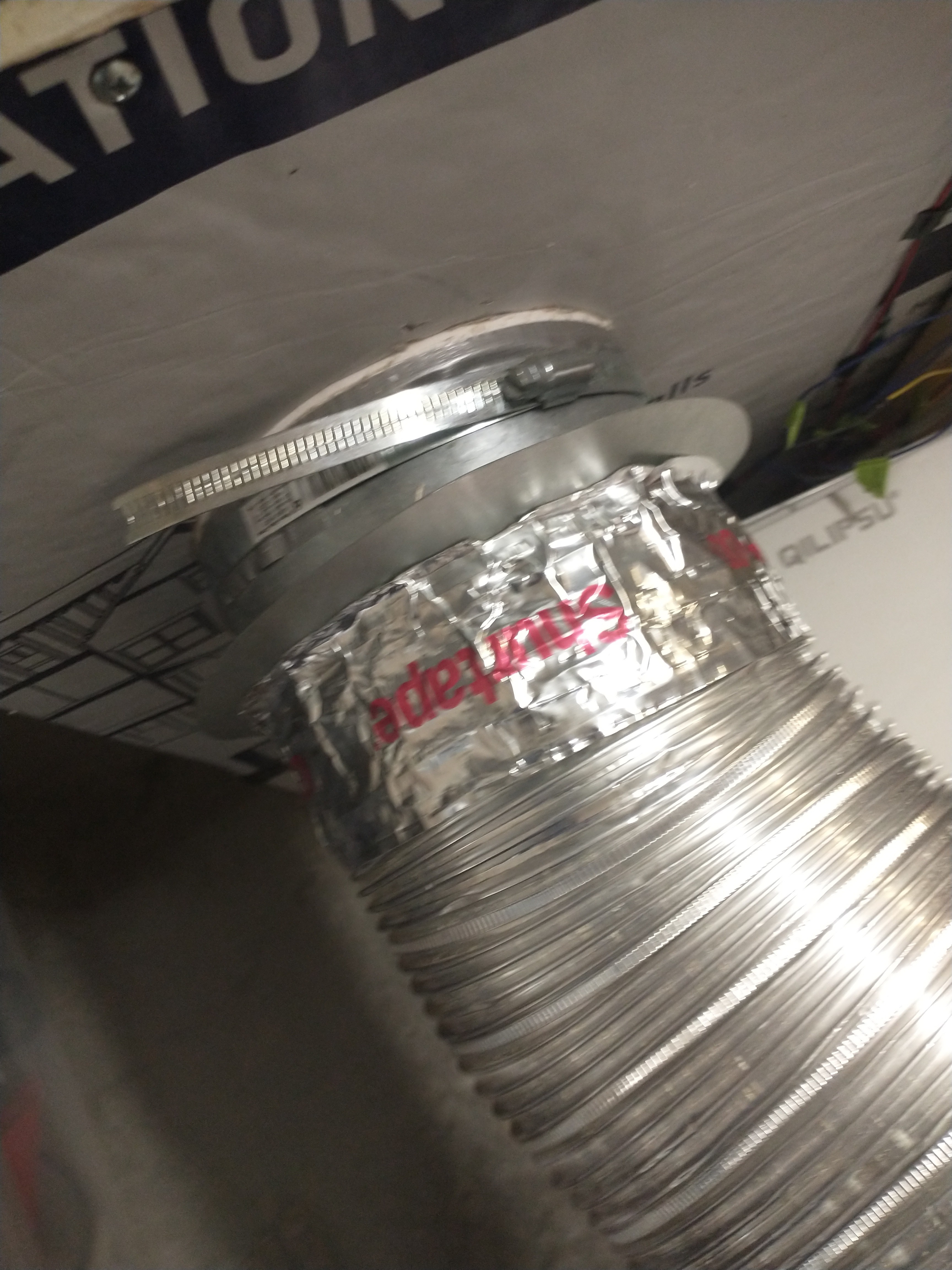
Finally I sealed the port with some Shurtape and a ducting clamp
![]()
-
MycoLab Update: Laminar Flow
09/07/2021 at 15:46 • 0 commentsWhat is a Laminar Flow:
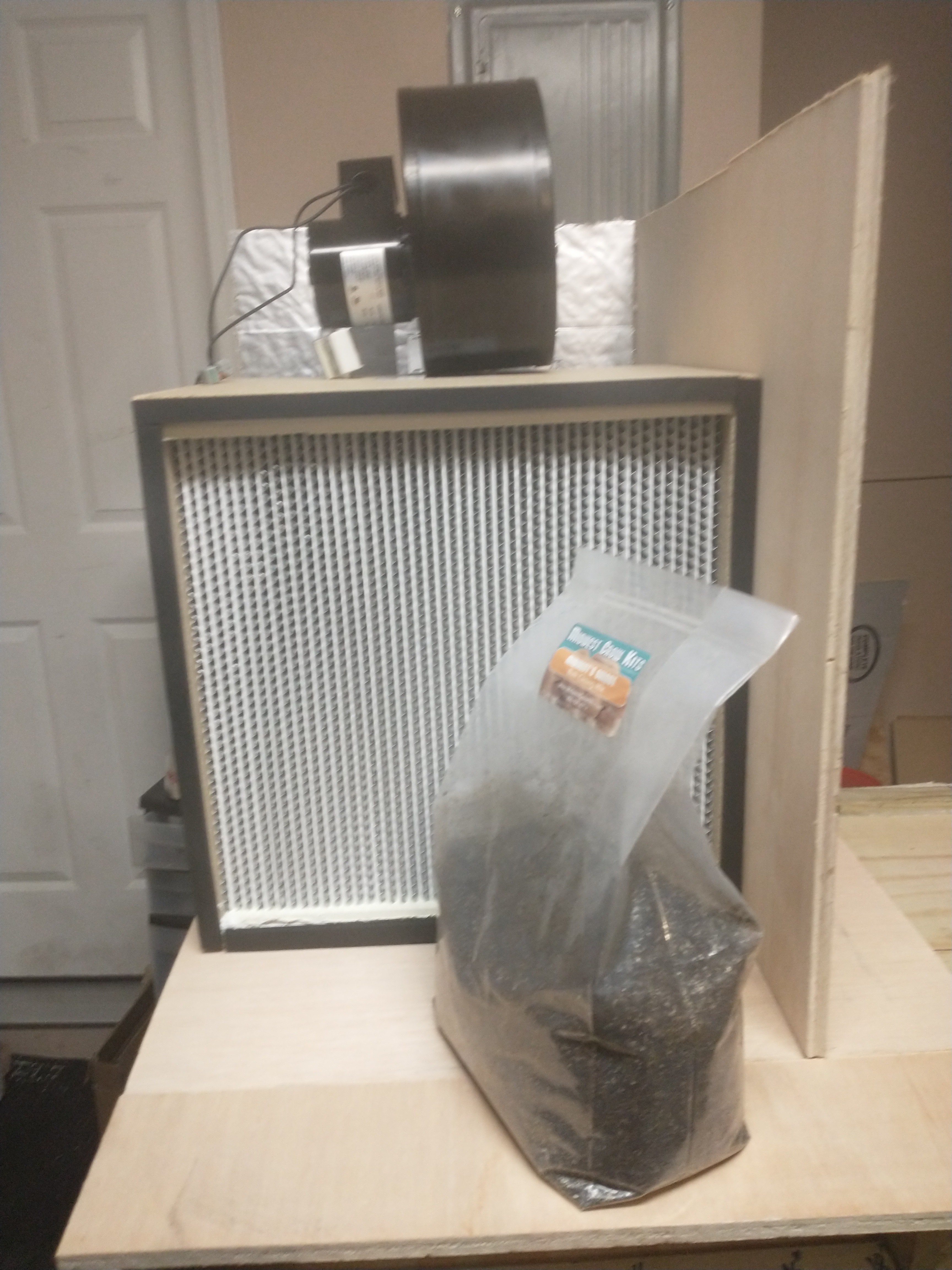
A laminar flow pushes air at a high rate, in this case 273 CFM, through a very large 99.97% HEPA filter. This means the space directly in front of the filter always has a flow of sterile air, making that immediate space a sterile work environment for any lab work to be carried out.
Matching a blower to a filter:
Generally the air speed of the air flowing from the filter surface must be 100 feet per minute or higher. To calculate your required fan CFM, simply multiply 100 feet/minute by the surface area of your filter. My filter is 16"x16", or 1.333 feet x 1.333 feet, which is an area of 1.77 feet. So I needed a fan that blows at least 177 CFM, based on the area of my filter. The other factor to consider is the static pressure of the filter, which is about 1" for most HEPA filters. The pre filter adds about an additional .1 to .2 static pressure, resulting in an approximate total of 1.2" of pressure between the two filters. The static pressure impacts the fans true CFM output, the higher the pressure the lower the actual CFM output of the fan will be. My fan is a replacement fan for the Dayton 1 TDR Fan, and it reduces from 273 CFM to 245CFM @ 1" static pressure. Even @ 4" static pressure this fan outputs 183 CFM, which is more than enough for my 16"x16" HEPA filter.
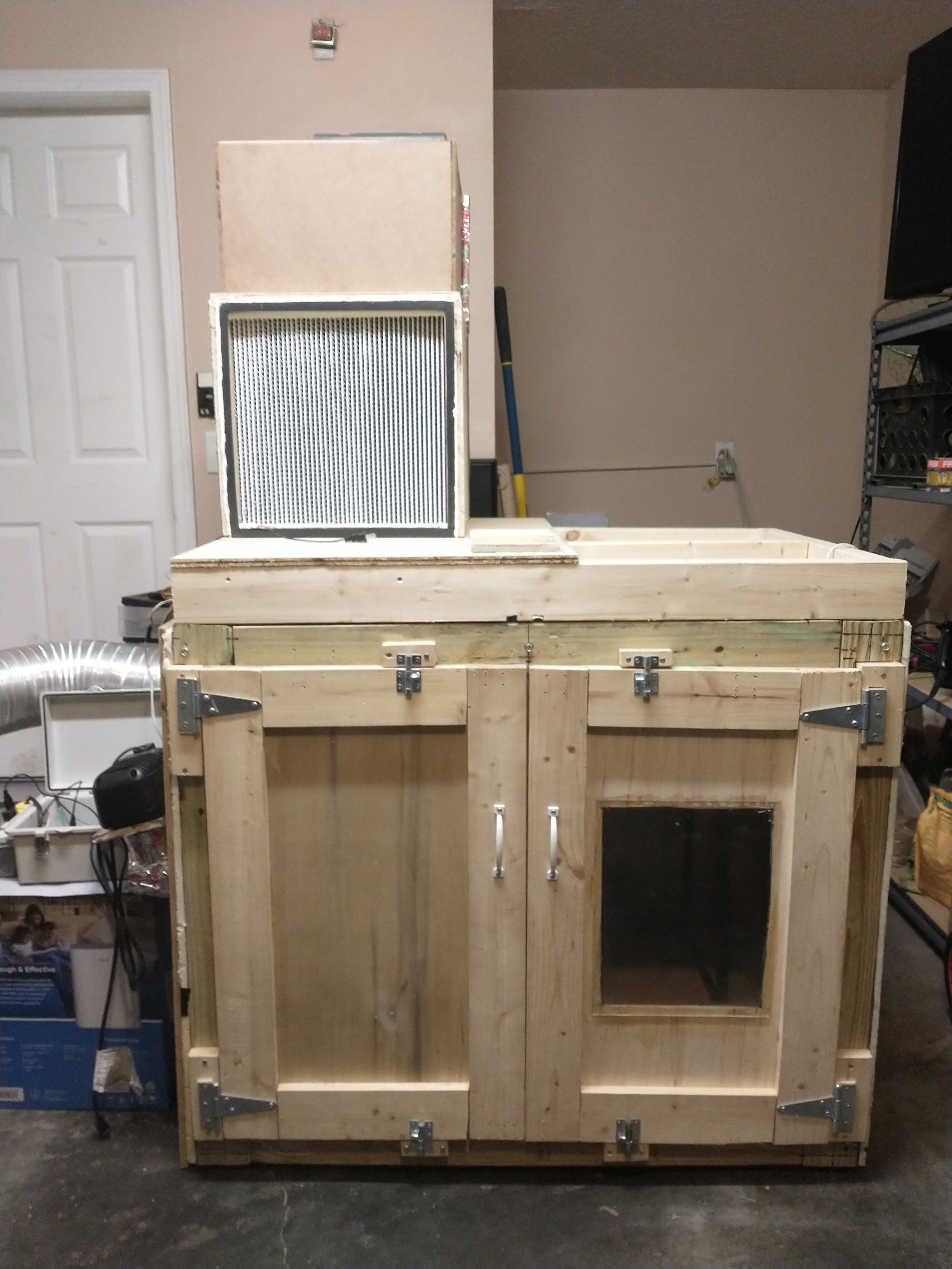
Photos from the build:
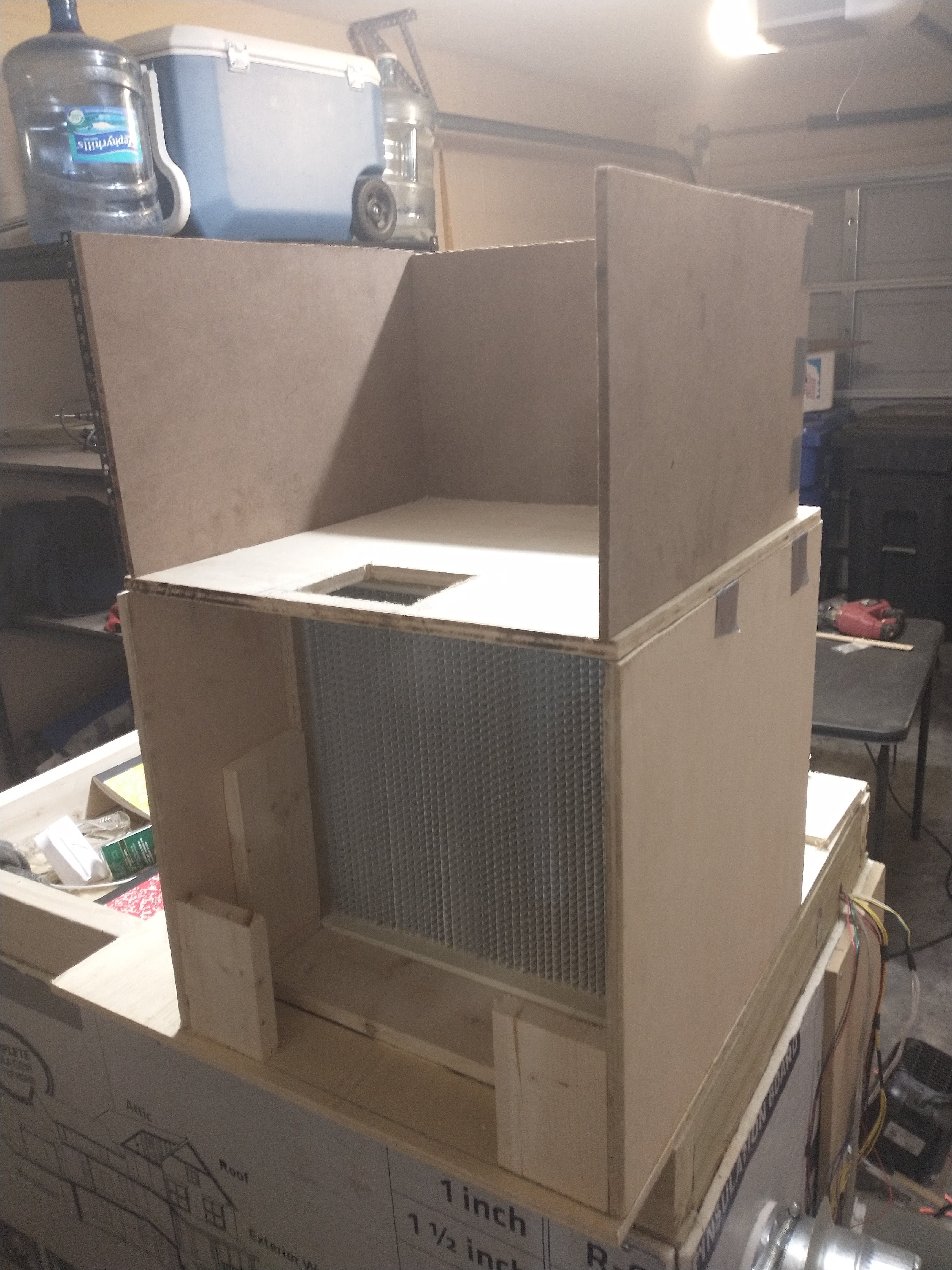
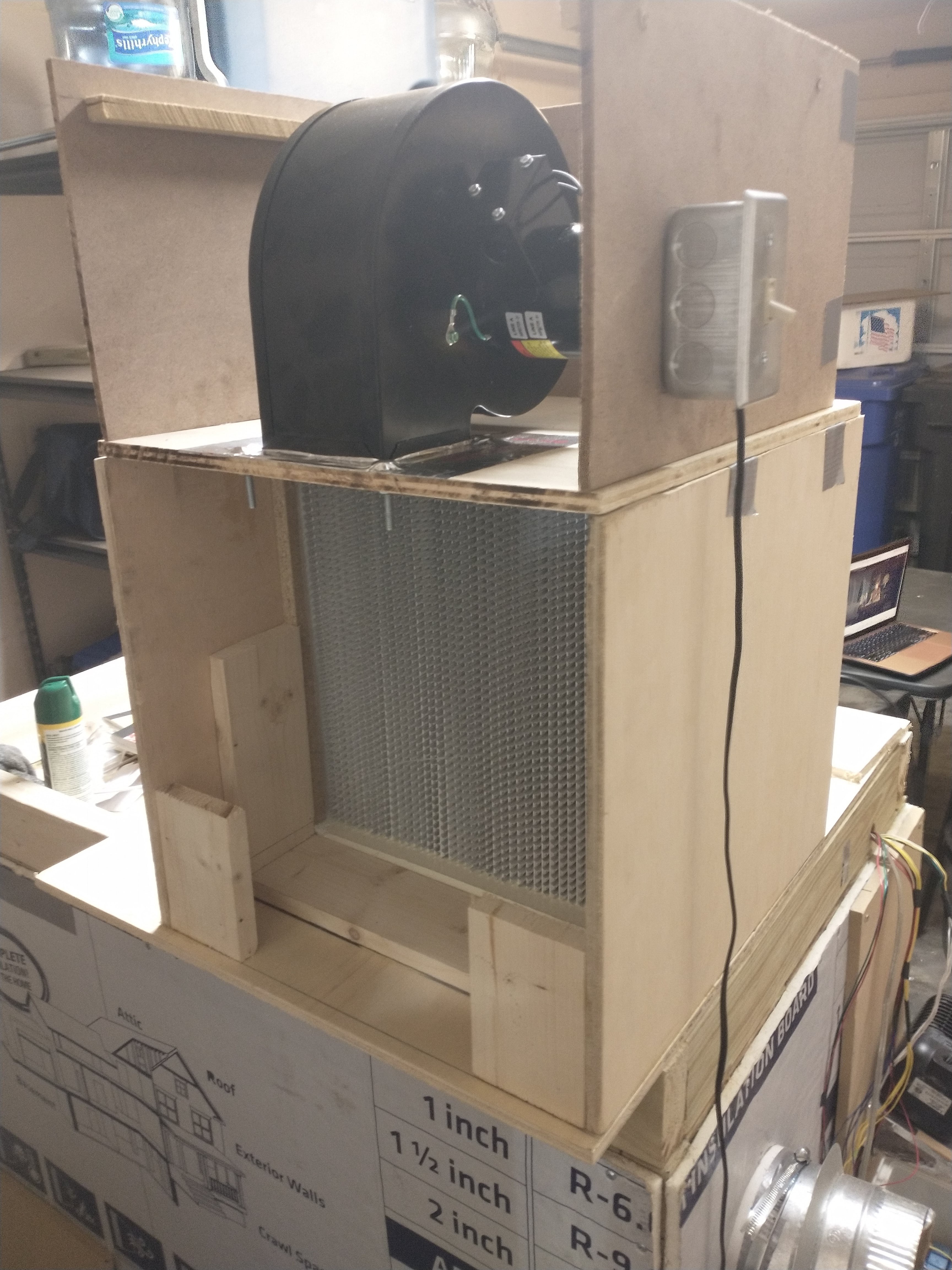
top view of the fan box that rests on top of the filter box
![]()
The fan port leads into the 16" wide x 16" tall x 6" deep sealed chamber behind the HEPA filter.
The planks directly touching the filter are glued to the walls, this way the filter is easily pushed into place from the front and will be stopped by these planks. The two planks nearest the missing back wall are for screwing the back wall into place
Also the back four inches of the laminar flow reach out beyond the lower MycoBox, this is to give more desk space in front of the filter to work with. Previously I considered extending the desk out over the front of the MycoBox, but I think it's better to just slightly hang the laminar flow over the back instead.
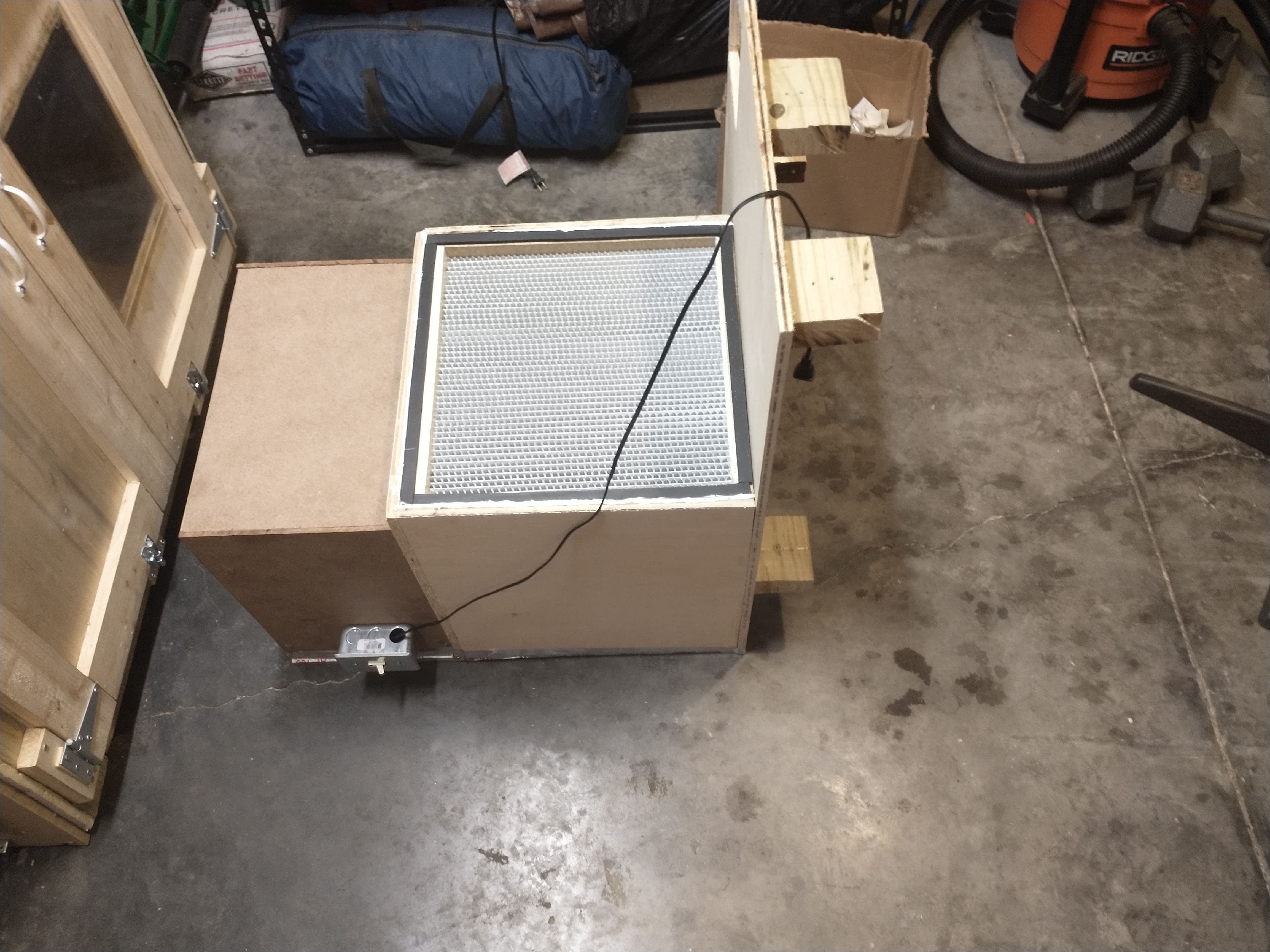
![]()
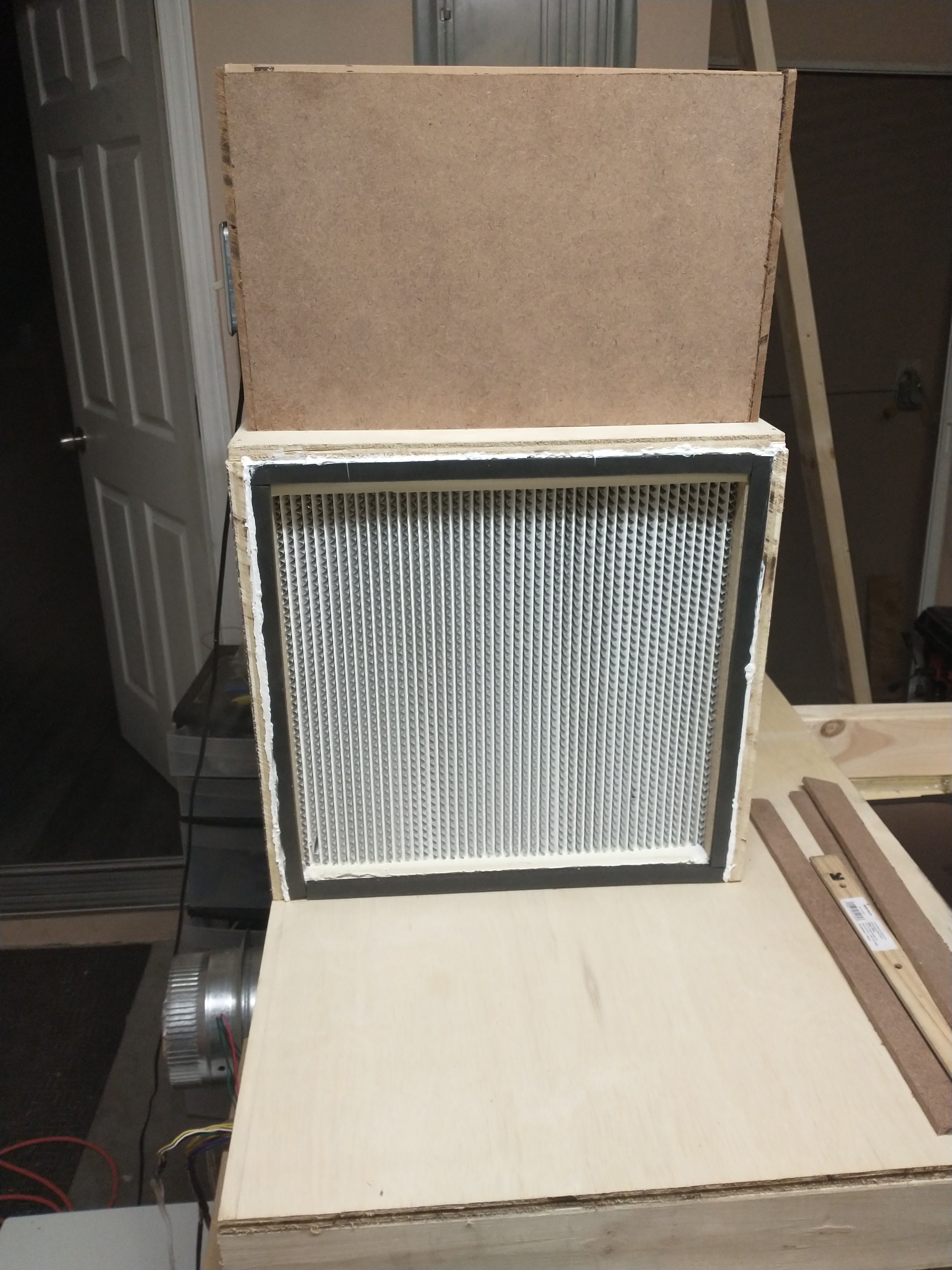
The Filter fits very snuggly in the containing box, however I still siliconed the area that the filter meets the box. When The filter has eventually expired, the back can be removed and the filter pushed out through the front. A new filter will be pushed into place from the front.
![]()
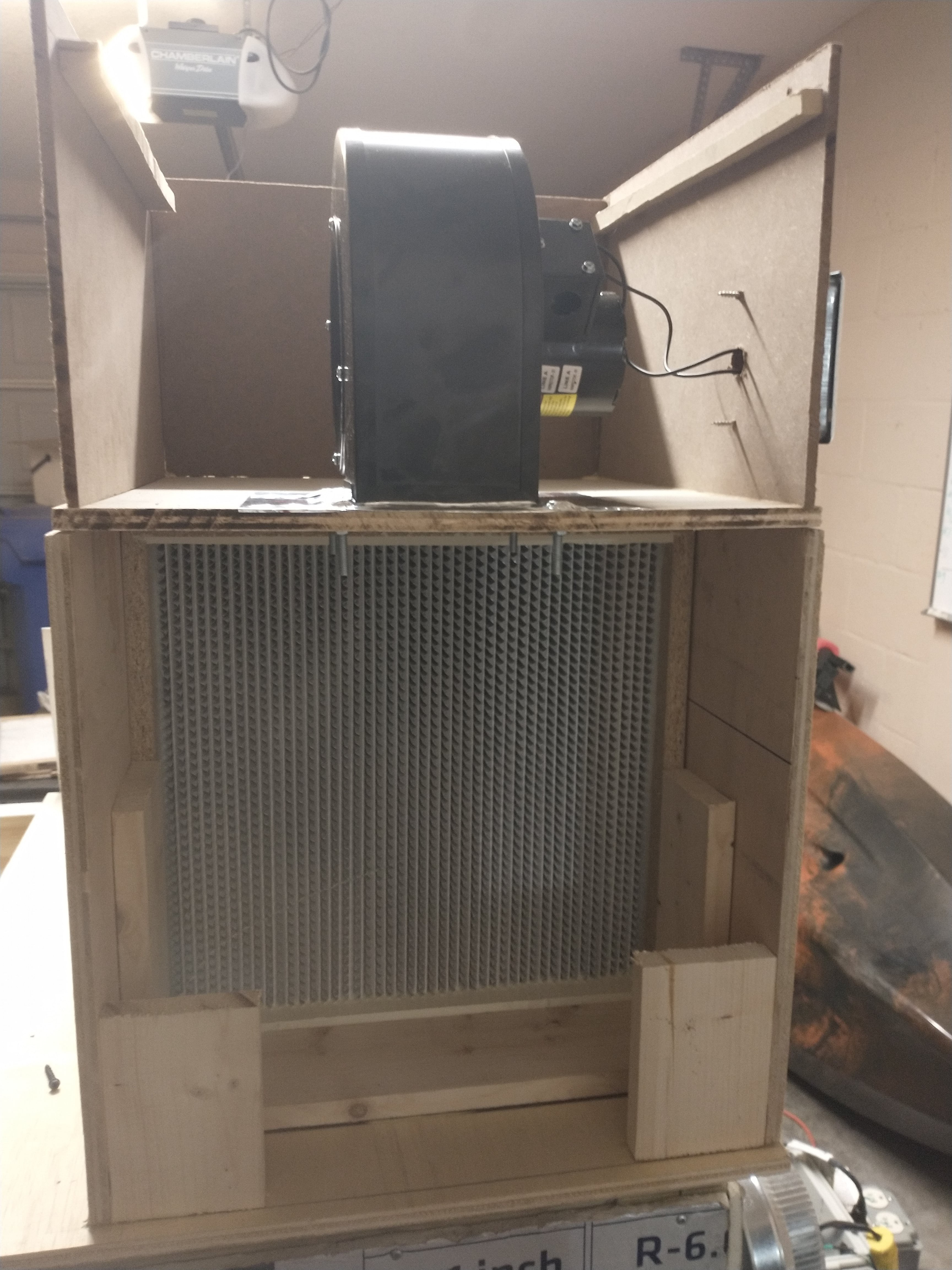
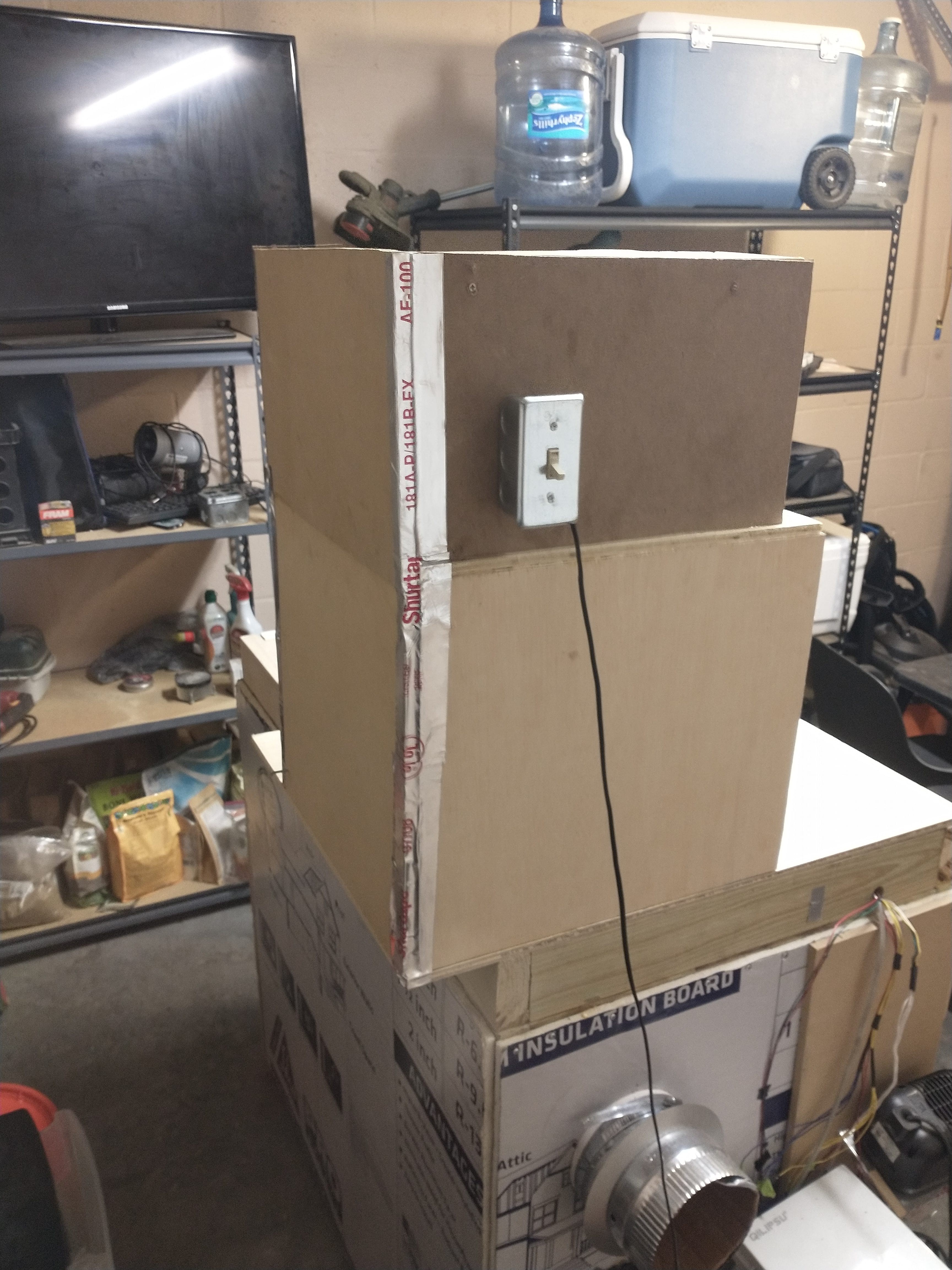
Here I'm securing the fan onto the port of the fan box. I've also screwed the pre-filter rims into place on the sides of the box.
![]()
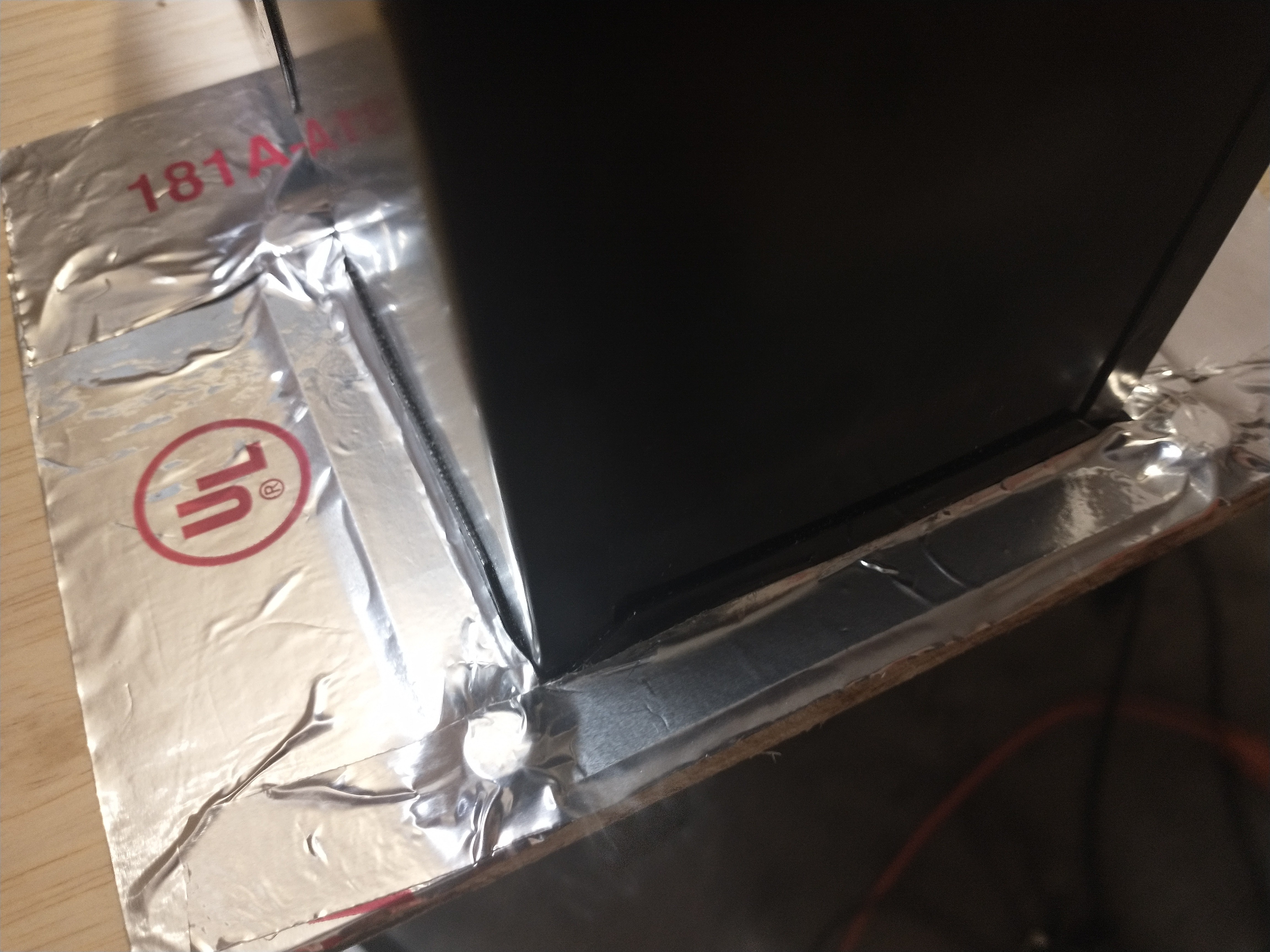
I covered the fan port with some ducting tape to make sure it's really sealed
![]()
![]()
![]()
Screwed the back into place and sealed it with ducting tape
![]()
Here is the pre-filter for the fan box
![]()
Building the Base of MycoLab
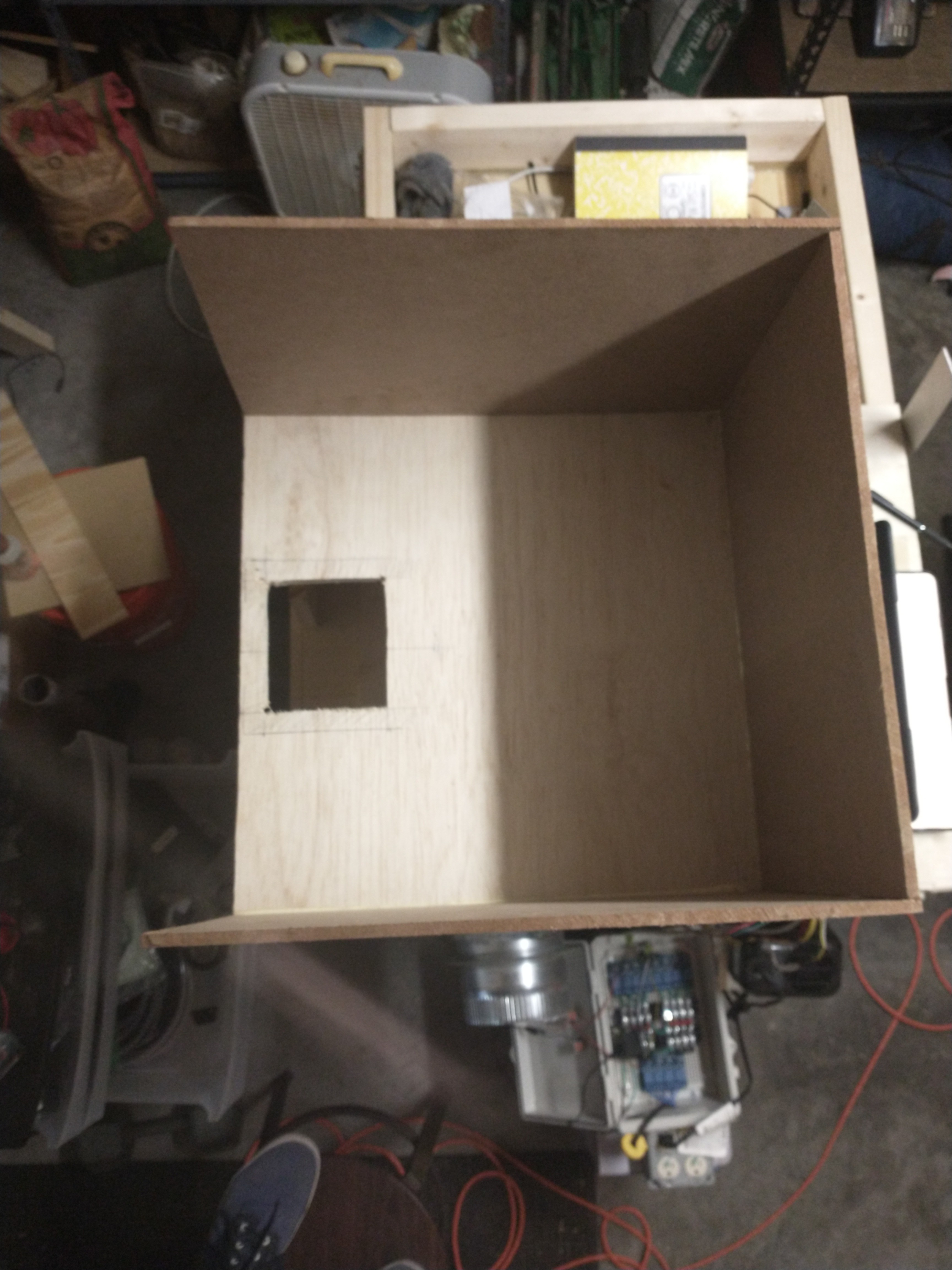
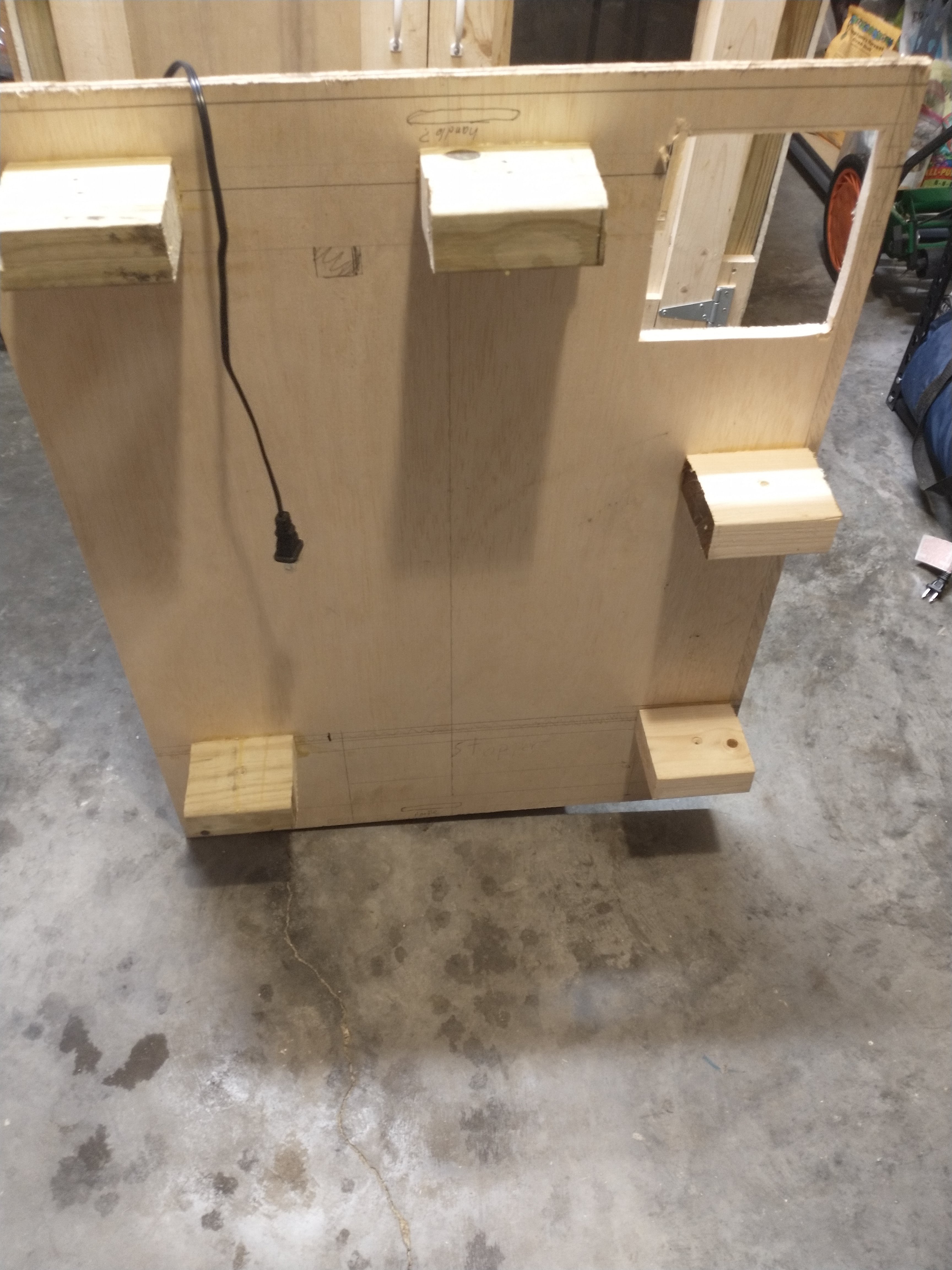
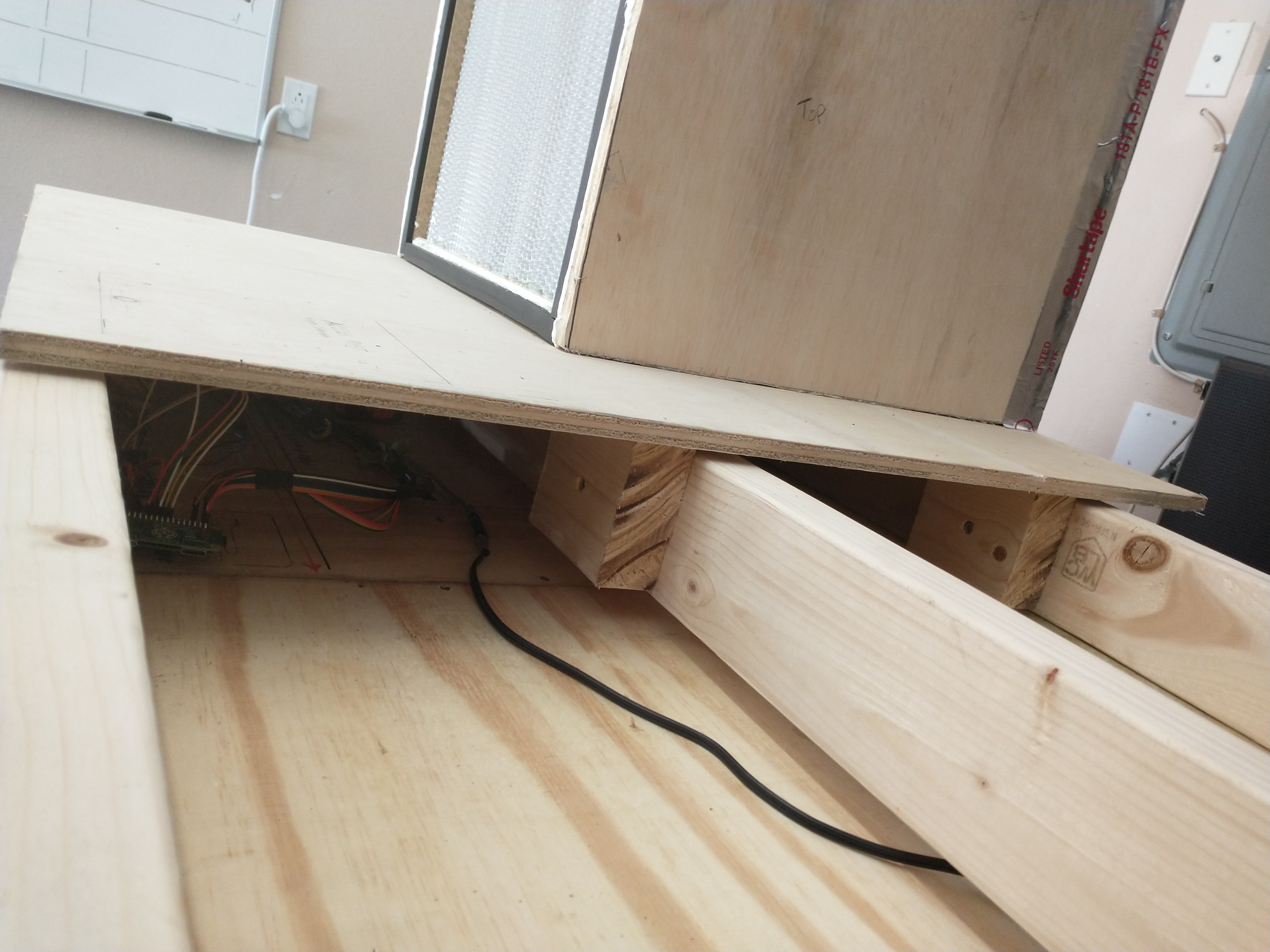
I mentioned in a previous post that the top sections of the MycoLab are not actually bolted onto the top of the MycoBox, instead they slide into place with pegs. The laminar flow makes up the left half of the MycoLab, below is a photo of the Laminar flow on its side.
![]()
The square cutout is the access port for the raspberry pi, it will have a hinged door on it
![]()
The Laminar flow can be used without the MycoBox and stand on it's own feet
![]()
The Base of the MycoLab, the electronics tray, is has three support beams for the MycoLab. The pegs of each MycoLab section lock tightly into the electronics tray.
![]()
In the image below, I'm actually gluing the pegs onto the bottom of the laminar flow section of the MycoLab. I screwed the pegs into place on the beams where they are intended to tightly slot into place, and I screwed each one in such that 1 cm of the peg is higher than the beam. I you look at the front beam you can see the shadow of the board hovering above it.
![]()
This video shows it better
Here's the access port cutout, it leaves enough space for a 1/2" wall to section off the laminar flow half of the MycoLab.
![]()
Here the laminar flow section is gluing to its pegs, and three pieces of scrap wood are demonstrating the amount of remaining desk space for the Mycolab. The back portion of the other half of MycoLab will also extend 4" beyond the back edge of MycoBox, giving more room for the front desk space as well as the incubator and equipment cabinet.
![]()
![]()
![]()
![]()
-
Temperature Controller Completed
09/07/2021 at 00:11 • 0 commentsWhat does the Temperature Controller do:
Drops or raises the internal temperature of MycoBox to the set-point temperature and then maintains that temperature.
Video Demonstration:
How it works in plain terms
The temperature controller subtracts the measured temperature from the set-point temperature to get the error; which is the number of degrees celsius the chamber is from the set-point temperature. The error value is run through a function that ‘decides’ how the Temperature Controller’s actuators should respond to the update value. When the error is a negative value the AC will be used, when it’s a positive value the heater will be used. Both the AC and heater have 3 modes; stopped, idle, and active. When a session begins the actuators are in stopped mode. If the chamber is more than .6 degree celsius too hot the AC will turn on, and if the chamber is more than .6 degree celsius too cold the heater will turn on. Once an actuator has switched on it is in active mode, and it will continue till it has lowered or raised the error to be within 0.2 of 0. At this point the actuator will remain on and switch to idle mode. If the error value remains within .2 of 0 for 3 cycles idle mode will end, if the error pushes back out of range before three cycles complete then idle mode will reset and keep watching. Idle mode is to make sure that the actuator is shutting off when the chamber temperature has truly reached the set-point and will maintain for some time without an actuator’s input. If the error cannot remain at least within .2 of 0 for three cycles, then the actuator will remain on and keep holding the chamber temperature nearly at set-point. The actuator is shut off once the error is stable for 3 cycles and idle mode switches to stopped mode. Now the temperature controller will watch and wait for the chamber temperature to move more than .6 degree celsius out of range, + or -, and then it will turn on the appropriate actuator to bring the temperature back to set-point. Note: I’m dropping the threshold from .6 to a lower value so temp is maintained closer to set-point. I point out why further along in the video analysis
Video Analysis
The thermocouple sensor is usually one to three degrees ahead of the DHT22 sensors 1 and 2 when the chamber temperature is first being set. I’ve noticed that this is because the thermocouple is secured nearly directly in front of the AC port and is cooling faster than the DHT22s that are secured on the opposite side of the box. If there is a large error between the set-point temperature and the actual temperature, then the thermocouple may drop two to three degrees celsius ahead of the DHT22s as the AC works to drop the temperature. You’ll notice this within the first 5 minutes of the video, as the precise temperature reading drops to 23.5 degrees while the DHT22s are both at 25.10 degrees.
The AC stops when the DHT22 sensors reach 24.40 and 24.80 degrees celsisu, and the thermocouple reaches 22.50 degrees. When the AC stops you’ll notice the DHT22 sensors’ readings continue to drop to 24.30 and 24.50 degrees, and the thermocouple’s readings actually begin to rise to 24 degrees because the AC is no longer blowing directly on the thermocouple and the chamber temperature is evening out to approximately the set-point. The measured value for the temperature is a weighted average of the DHT22s and the thermocouple, and the thermocouple is given more weight than the individual DHT22s.
Once the set-point is reached the AC switches from active to idle, and then finally stopped mode. From there it will wait for the temperature to exceed more than 0.6 from the set-point temperature before switching the AC back on and into active mode. You can see this at 8:03 minutes into the video, and the sensor readings are 24.50, 24.6, and 24.75. It took about 3 minutes for the AC to switch back on after it stopped the first time in the video. I will add some more insulation to the ceiling of the MycoBox, and seal the sensor port leading into the box, so the chamber will maintain its temperature for even longer.
Code Overview:
This section outlines how the code is working. It begins with the new_session function.
function newSession(config) {
    return new Promise ( (resolve)=> {
        const session_state = get('session_state');
        if (!session_state.active_session) {
            set_environment_config(config)
                .then(update_environment_state())
                .then(set_session_state('active_session', true))
                .then(environment_manager())
                .then(resolve())
                .catch(err => console.log(`Error Caught: new_session: ${err}`))

        } else {
            throw new Error('There is already an active session')
        }
    });
}
new_session starts an environment manager session with the configuration from the web application. The function first uses the submitted configuration form to initialize the session by setting the global configuration that runs an environment manager session. The global environment configuration is set with the values entered into the configuration form by the user. Then the session state is set to active and the correct stage in the session is set to true, which at the start is spawn running. The global environment state is set with initial sensor readings and then finally the environment manager function is called.
/**
 * Responsibilities: Calls Promises
 * i. coordinates through three session stages
 * ii. maintain PID states
 * iii. call each EM PID
 */
const environment_manager = () => {
    console.log('METHOD CALL: environment_manager')
    // #1. Validate the session is still active and THEN
    validate_active_session()
        .then((validation) => {
            console.log('Validation Results: ' + validation)
            // #2. Process the current session_state, and don't do anything until its done; not sure why it's async

            // #3. calculate measured and generated a pid_config WHEN valid env_state returned
            if (validation) {
                console.log('Environment Manager Has Validated Session')
                update_environment_state()
                    .then(run_pid_controllers()
                        .then(data => {
                            // if there is any data returned do whatever with it here
                            // otherwise recall environment_manager, because the session must still be active
                            console.log('#############################################################################')
                            console.log('Update Value Returned | ' + data + ' | Recalling ENV MANAGER')
                            console.log('#############################################################################')

                            setTimeout(() => {
                                console.log('**************************** Waited 2 Seconds ****************************')
                                return environment_manager();
                            }, 4000);
                        }))

            }
            if (!validation) {
                resolve('Session has ended')
            }
        })
}
The environment_manager calls for the latest sensor readings of the environment, then passes the environment state to the four environment controllers; temperature, humidity, ventilation, and circulation. These 4 controllers are managed by the run_pid_controllers function.
/**
 * Validate the current environment state, then calculate the measured values and call each controller with its
 * respective configuration object
 * @param {*} env_state
 * @returns { temp, humidity, co2 }
 */
const run_pid_controllers = () => {
    console.log('Running PID Controllers now ------------------------------------------------------------------------')
    return new Promise((resolve) => {
        validate_env_state()
            .then(validation => {
                console.log(validation['env_state'])
                if (validation.validation) {
                    console.log('$$$$$$$$$$$$ The Environment State Was Validated $$$$$$$$$$$$')
                    const measured = calculate_measured(validation.env_state);
                    // =========================================================================================================
                    // todo: check for session stage (sr, pi, fr)
                    // generate config for each controller: add the other controller functions for this
                    get_state()
                        .then(state => {
                            console.log(state)
                            const config = temp_pid_controller_config(measured, state[0].spawn_running, state[2].temperature)
                            console.log('Call Each PID');
                            return update_temperature(config)
                        })
                        .then(results => resolve(results))
                }
            })
    })
}
Run PID controllers validates that the environment state is filled out with all the necessary data, it will continually recall for sensor readings till the environment state is validated. Next it will calculate a measured temperature and humidity from the environment state by taking a weighted average of the 4 internal temperature readings and the 3 internal humidity readings (note: sensor 3 is down right now, I’m only using DHT22 #1 and #2). Next a configuration object is created for each controller class and all 4 controllers will be called with the data they need to start and command their respective actuators; however right now I’ve only completed the Temperature Controller
Temperature Controller Code
/**
 * Temperature Controller: PID and Overrides
 * design of PID greatly influenced by https://github.com/Philmod/node-pid-controller/blob/master/lib/index.js
 * & https://gist.github.com/DzikuVx/f8b146747c029947a996b9a3b070d5e7
 * ----------------------
 * How this is going to work:
 * Could be that the controller calls it everytime with env_sate, and runs the function with the previous report
*/

const { set_pid_state, get, set_actuator_state } = require('../../globals/globals');
const { TempPidController } = require('../../services/environment.manager/temperature.pid.service');
const { s2r1_off, s2r1_on, s1r1_on } = require('../../cli_control_panel/relay');

/**
 * Run PID:
 * Run the PID service with the latest measured value, and any configuration updates
 * @param {
 *  settings: {
 *    kp,
 *    ki,
 *    kd,
 *    iLimit
 *  },
 *  previousReport: {
 *    integralOfError,
 *    lastError,
 *    lastTime
 *  }
 *  incomingReport: {
 *    setPoint,
 *    measured
 *  }
 * } config the previous (or initial) report & the incoming
 */
const update_temperature = (config) => {
    // initialize the controller
    const tempController = new TempPidController(config);
    // update the actuator
    const value = tempController.update();
    console.log('The calculated Update Value')
    console.log(value);
    set_pid_state('temperature', tempController.report())
    temp_actuator_controller(value)
    return value
}

/**
 * Create TemperauturePidController config
 * Todo: move this to the temperaturePidController
 */
const temp_pid_controller_config = (measured, env_config, pid_state) => {
    console.log('Method Call: temp_pid_controller_config')
    const config = {
        settings: {
            kp: 1,
            ki: 0.005,
            kd: 0.005,
        },
        pid_state: {
            integralOfError: pid_state.integralOfError,
            lastError: pid_state.lastError,
            lastTime: pid_state.lastTime,
        },
        incoming_report: {
            setPoint: env_config.temperature,
            measured: measured.temperature
        }
    }
    return config
}

/**
 * Override:
 * Purpose: Manually switch the acuator on or off if OVERRIDE is true
 * Description: Commands the selected actuator to turn on/off regardless of the global context (EnvModel, SystemStatus, ...)
 * @param {string, string} command {actuator: '', status: ''}
 */
const override = (command) => {
    switch (command.actuator) {
        case 'AC':
            if (command.status === 'ON') s1r1_on();
            if (command.status === 'OFF') s1r1_off();
            break;
        case 'HEATER':
            if (command.status === 'ON') s2r1_on();
            if (command.status === 'OFF') s2r1_off();
            break;

        default:
            break;
    }
}

/**
 * Temp Actuator Controller
 * if the update value is greater or equal than +/- 1 from 0 for 3 consecutive readings, then turn on the appropriate acuator and enter 'set mode'
 * once the update value hits within 0.2 of zero or switches positive/negative, stop and don't start until more than or equal to +/-1 from 0 again
 * actuator will stay on till update value can reach .2 of 0, and then it'll switch on again once the update is > or = +/- 1 for 3 consecutive readings
 */
const temp_actuator_controller = (update) => {
    // #2. Check the actuator state
    get('actuators_state')
        // The switch on threshold (st) should be a variable
        .then(state => {
            if (state.ac.active) {
                // check if update is within -0.2 from 0
                const idle = idle_check(update, false)
                console.log('Temp Actuator Controller: Active ^^^^^^^^^^^^^^^^^^^^^^^^^^^^^^^^^^^^^^^^^^^^^^^^^^^^^^^^^^^^^^^^^^^^^^^^^^^^^^')
                switch (idle) {
                    case 1: // AC switches to idle
                        set_actuator_state('ac', 'active', false).then(set_actuator_state('ac', 'idle', 1))
                        break;

                    case 2: // AC stays ON
                        set_actuator_state('ac', 'active', true)
                        break;

                    default:
                        break;
                }
            }
            if (state.ac.stopped) {
                // Start if more than .5 or .7 off not 1
                console.log('temp_actuator_controller: Stopped^^^^^^^^^^^^^^^^^^^^^^^^^^^^^^^^^^^^^^^^^^^^^^^^^^^^^^^^^^^^^^^^^^^^^^^^^^^^^^')
                const stopped = remain_stopped_check(update, false)
                switch (stopped) {
                    case 1: // AC stays OFF
                        console.log('AC Remain Stopped')

                        break;

                    case 2: // AC switches ON
                        console.log('AC Switching Active')
                        set_actuator_state('ac', 'stopped', false).then(set_actuator_state('ac', 'active', true).then(() => s2r1_on()))
                        break;

                    default:
                        break;
                }
            }
            if (state.ac.idle > 0) {
                console.log('temp_acutator_controller: Idle ^^^^^^^^^^^^^^^^^^^^^^^^^^^^^^^^^^^^^^^^^^^^^^^^^^^^ ' + state.ac.idle)
                const idle = idle_check(update, false)
                console.log('IDLE CHECK CODE: ' + idle)
                switch (idle) {
                    case 2: // switch back to active
                        console.log('AC Switching Back to Active')
                        set_actuator_state('ac', 'idle', 0).then(set_actuator_state('ac', 'active', true))
                        break;

                    case 1: // increment up or switch to stopped and turn off the ac
                        if (state.ac.idle >= 3) {
                            console.log('AC Switching OFF From Idle ')
                            set_actuator_state('ac', 'idle', 0).then(set_actuator_state('ac', 'stopped', true)).then(() => s2r1_off())
                        } else {
                            console.log('Incrementing Idle:')
                            const increment = (state.ac.idle + 1)
                            console.log('Increment: ' + increment)
                            set_actuator_state('ac', 'idle', increment)
                        }
                        break;

                    default:
                        break;
                }
            }
            // Heater Protocol
            if (state.heater.active) {

            }
            if (state.heater.stopped) {

            }
            if (state.heater.idle) {

            }
        })
}

/**
 *
 * @param {*} update
 * @returns
 * 1: AC switches to idle
 * 2: AC stays ON
 * 3: Heater stays OFF
 * 4: Heater turn ON
 */
const idle_check = (update, sign) => {
    console.log('Idle Check Starting')
    // check if within .2 for sign
    switch (sign) {
        // positive sign
        case true:
            console.log('Idle Check: Positive Sign')
            // within .2 of zero
            if (update <= 0.2) {
                console.log('Within 0.2')
                return 3
            }
            // more than .2 from zero
            if (update > 0.2) {
                console.log('Outside 0.2')
                return 4
            }
            break;
        // negative sign
        case false:
            console.log('Idle Check: Negative Sign')
            // within -.2 of zer0
            if (update > -0.2) {
                console.log('Within 0.2')
                return 1
            }
            // less than -.2
            if (update < -0.2) {
                console.log('Outside 0.2')
                return 2
            }
            break;

        // default
        default:
            break;
    }
}

/**
 *
 * @param {*} update
 * @returns
 * 1: AC stay OFF
 * 2: AC turn ON
 * 3: Heater stay OFF
 * 4: Heater turn ON
 */
//NOTE: the comparator value should be a parameter?
const remain_stopped_check = (update, sign) => {
    // check if within .2 for sign
    switch (sign) {
        // positive sign
        case true:
            console.log('Remain Stopped Check: Positive Sign')
            // within 1 of zero
            if (update <= .6) {
                console.log('Update is Less than .5 greater than 0')
                return 3
            }
            // more than 1 from zero
            if (update > 0.6) {
                console.log('Update is Greater than 1 from 0')
                return 4
            }
            break;
        // negative sign
        case false:
            console.log('Remain Stopped Check: Negative Sign')
            // within -1 of zer0
            if (update > -0.6) {
                console.log('Within 1')
                return 1
            }
            // more than -1 from zero
            if (update < -0.6) {
                console.log('Outside 1')
                return 2
            }
            break;
        // default
        default:
            break;
    }
}


module.exports = {
    update_temperature,
    temp_pid_controller_config,
    override
}
And here is the temperature.pid.service class used by the temperature controller
/**
 * PID Controller Class
 * @param {number} kp proportional gain
 * @param {number} ki integral gain
 * @param {number} kd derivative gain
 * @param {min: number, max: number} iLimit limits for the integral
 * ----------------------------------------------------------------------------------------
 * Steps:
 * #1. create a new controller: e.g. let tempCtr = new TempPidController(0.25,0.01,0.01)
 * #2. create the set-point: e.g. tempCtr.setPoint(21)
 * #3. read the updated environment model every time it's available; flag indicating updated
 */
 class TempPidController {
    constructor(config) {
        // saturation has been reached if these limits are hit and clamping should happen
        let defaultIntegralLimit = { min: -10, max: 10}
        // Set PID weights (gain)
        this.kp = config.settings.kp || 1;
        this.ki = config.settings.ki || 0.1;
        this.kd = config.settings.kd || 0.1;
        // init properties for the integral of error
        this.integralLimit = config.settings.iLimit || defaultIntegralLimit;
        this.integralOfError = config.pid_state.integralOfError;
        this.lastError = config.pid_state.lastError;
        this.lastTime = config.pid_state.lastTime;
        // init the set point
        this.setPoint = config.incoming_report.setPoint;
        this.measured = config.incoming_report.measured;
        console.log('This: TempPidController Properties')
        console.log(this)
    }

    update() {
        // #1. find the cycle-time (dt) and update lastTime
        const {dt, currentTime} = this.calculate_dt(this.lastTime)
        let D;
        this.lastTime = currentTime;
        // #2. calculate the error: setpoint - measured
        const err = this.setPoint - this.measured;
        this.lastError = err;
        // #3. calculate P => kp * err
        const P = this.kp * err;
        // #4. calculate It => It + (ki * error * dt)
        this.integralOfError += (this.ki * err * dt)
        // #5. limit the It
        if (this.integralOfError > this.integralLimit.max) this.integralOfError = this.integralLimit.max;
        if (this.integralOfError < this.integralLimit.min) this.integralOfError = this.integralLimit.min;
        // #6. calculate D => kd * (err - lastErr) / dt
        dt === 0 ? D = 0 : D = this.kd * (err - this.lastError) / dt;
        return P
    }

    // set the global pid state for this controller
    report() {
        return {
            integralOfError: this.integralOfError,
            lastError: this.lastError,
            lastTime: this.lastTime
        }
    }

    reset () {
        this.integralOfError = 0;
        this.lastError = 0;
        this.lastTime = 0;
    }
    // calculate_dt
    calculate_dt(lastTime) {
        const currentTime = Date.now();
        let dt;
        if (lastTime === 0) {
            dt = 0;
        } else {
            dt = (currentTime - lastTime) / 1000;
        }
        return {dt, currentTime};
    }
    // clamp_check
    clamp_check() {

    }
}

module.exports = {
    TempPidController,
}
The humidity, Ventilation, and Circulation controllers will be true PID controllers, however the Temperature controller is just a P controller as described above. This is because the air conditioner runs at 11 amps, and I do not want to use a AC phase control module to throttle its current, instead I only switch the ac on or off. The Controllers are initialized with the settings for the PID, the previous PID data, as well as the set-point and current measured value. The controllers calculate their update value and then pass it to their actuator_controller, which decides how to respond to the update value. Once each controller has run, the environment manager recalls itself, and it will continue this loop till the session has progressed through all three stages and ends.
*Note: You may have noticed, if anyone cares to read this that closely, that the TempPidController class calculated the integral and derivate, but only returns the P. This is because the TempPidController is setup to be a PID controller but I realized after the fact I just need it to use the proportional error. The other controllers will use the same code structure, however they will return the P + I + D as their update value. Also you may have noticed I have not filled in the code for the heater in the temp_actuator_controller function of the temperature.controller.js file. I will be filling that in tonight.
Additional functionality coming soon:
One other feature I'm considering to add to the temperature controller is a ventilation alternative to the AC or heater. If the external temperature is at or beyond the set-point temperature the intake fan can be switched on to adjust the chamber temperature. This option depends on the stage of the session and pretty much could not be used in the spawn running stage when the CO2 levels need to be high.
-
Big Hardware Update
07/25/2021 at 04:41 • 0 commentsIntro:
last week I was working on a few different parts of MycoHub's hardware, as well as pushing the software along for the controlled environment.
- Added the ceiling / Raspberry Pi pan to the MycoBox and varnished it
- Modeled how the Laminar flow will fit on the MycoLab (above the Raspberry Pi pan)
- Created a prototype board to organize the sensors' and relays' wiring to the Raspberry Pi
- Switched the AC port with a much smaller one
1 ) Raspberry pi pan & the MycoBox ceiling
![]()
^ MycoBox flipped upside down to varnish the ceiling, all of the interior wood is double varnished
![]()
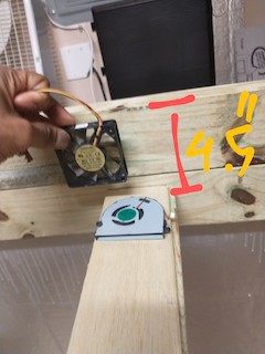
^ Raspberry Pi pan (MycoBox attic / MycoLab basement)
The Raspberry Pi is positioned in this 4.5" deep pan above the MycoBox. The sensors will drop into the MycoBox, the relay wires will come through a port on the left of the Raspberry Pi pan, and the wires from the fans on the right side of the box cross through this section to reach the relays on the left as well. This way all wiring is above the MycoBox and below the Mycolab, while the main power lines are kept safely in a junction box on the left side of the MycoBox.
![]()
^ Junction box for the 2 relays. This is just showing how the relays will fit inside the box, I will actually assemble and mount this tomorrow.
![]()
^ This 4.5" spacing, as mentioned in a previous post, gives enough room to add ventilation fans to the Raspberry Pi pan; which may not be necessary, but just incase things get hot after running the MycoBox for a 4 week fruiting session. It also raises the MycoLab to the perfect standing desk height for me, I'm 6'2".
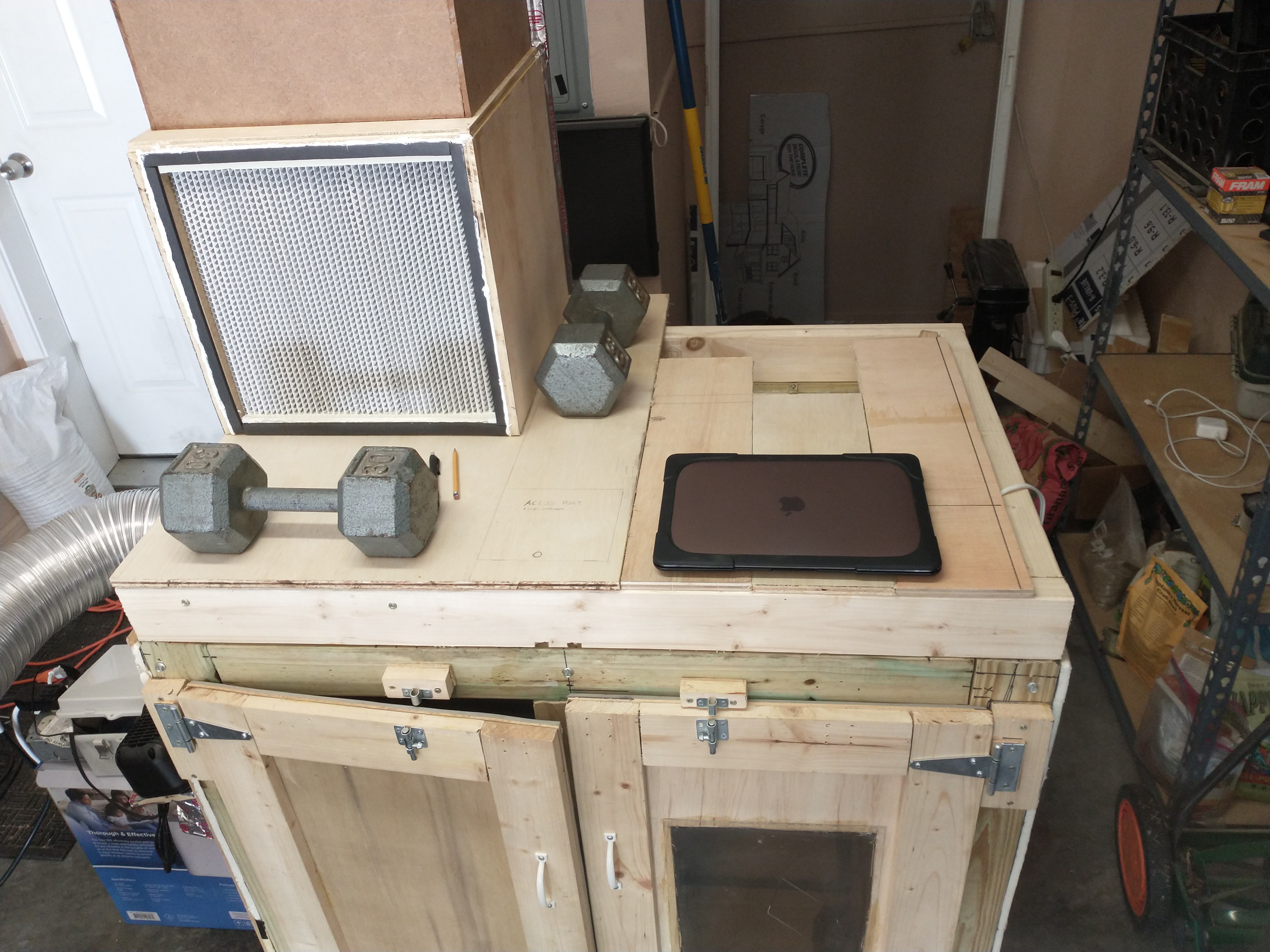
2) 16" x 16" x 11.5" Laminar Flow
![]()
^ This is not constructed yet, just demonstrating the spacing and location of the laminar flow. The 16" wide filter gives enough room to inoculate grow bags comfortably, and it takes up less than half of the available table space. It's also of course very easy to start agar plates, or do any other lab work in front of this.
![]()
^ This is image is just showing the amount of space left available. I haven't added the remainder of the ridge that lifts the MycoLab above the MycoBox, and need to get another board for the base of the MycoLab; I accidentally did a terrible job sizing and cutting the board the first time.
![]()
^ This is a 273 CFM centrifugal blower fan, which is enough to keep the air speed through the filter well above 100 fpm. I determined the minimum required fan speed by multiplying the 1.77 foot surface area of the filter by the 100ft/min rate air speed, which calculates to a 177CFM fan. The space behind the filter is 6" deep and will be a closed box that the fan mounts on top of. The fan itself will also be in a closed box with the only vent having a pre-filter on it, which is to keep larger particles from ever reaching the laminar flow filter. It will be built in a way that makes it easy to slide the filter out for replacement when the time comes. This is pretty much the only hardware that won't be connected to the raspberry pi, there will simply be a switch for turning the fan on or off.
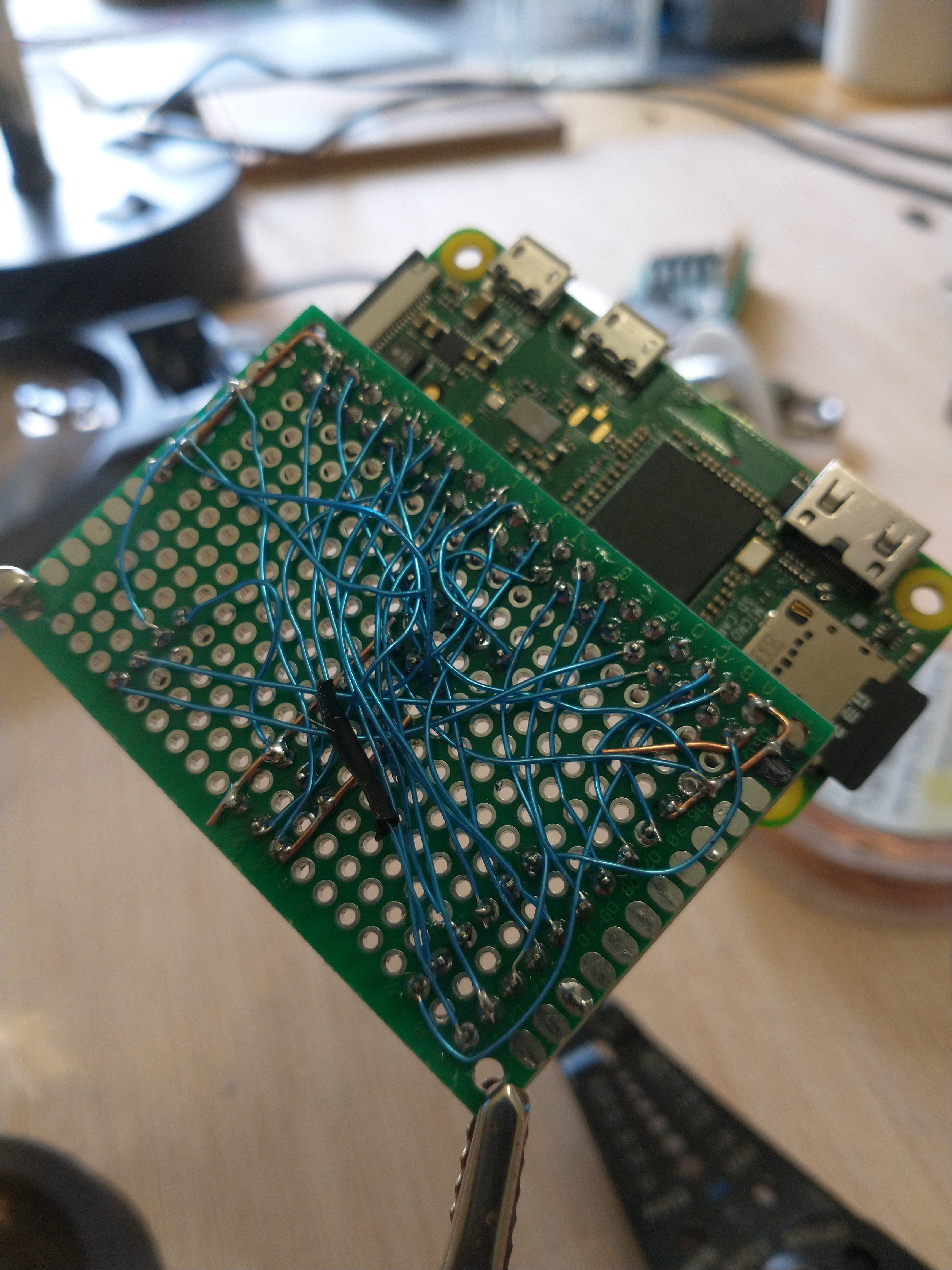
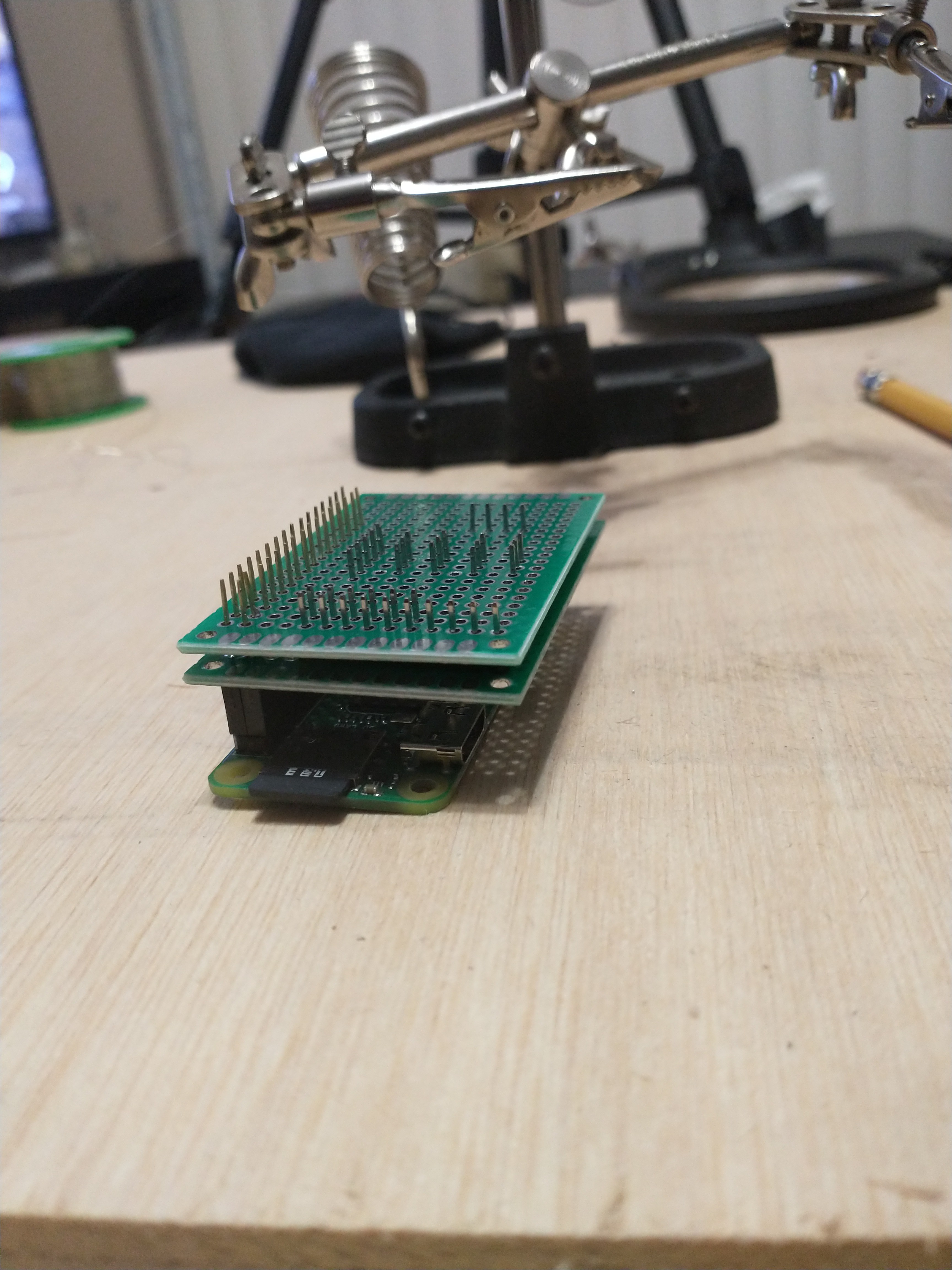
3) Raspberry Pi Prototype Board
I created a prototype board to organize the bird nest of sensor and relay wires connecting to the Raspberry Pi GPIO. Instead of plugging into the default GPIO each sensor and relay gets a designated plug.
![]()
^ finished version 2 ( I had to scrap the first attempt and change the design). The left most pins are for the 8 channel relay (relay 2), and the row second from the left is for the 4 channel relay (relay 1). The top middle pins are for the MAX31855 thermocouple, and the 4 others in the middle are for DHT22 sensors. The first three DHT22s will be placed in the bottom, middle, and top section of the Mycobox, while the 4th is tracking the temperature and humidity outside of the box. The thermocouple is very precise and will have the most weight for controlling the PID that maintains the box temperature. Finally, the right most pins are for the co2 sensor, which is mounted just about midway in the MycoBox.
![]()
^ The bird nest is now tucked hidden under this board, never to be disturbed again
![]()
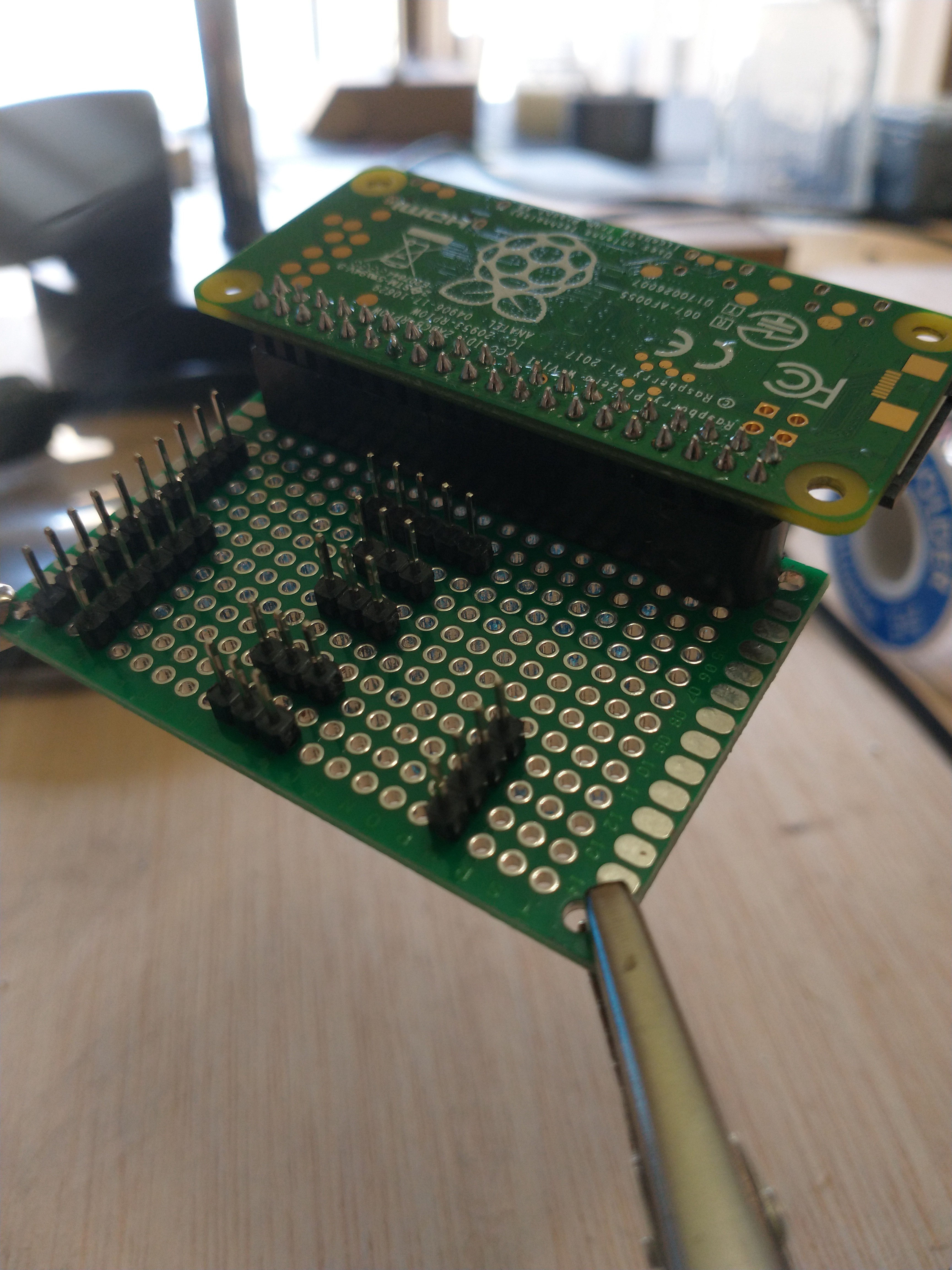
^ This is version 1, the original design that tragically didn't quite work. I placed the board directly above the Pi to reduce space and I soldered everything together in that middle layer, however the pins were not tall enough to attach to the sensors after added the second board like this.
![]()
^ verifying that every relay and sensor is working; didn't verify the co2 meter yet, will do that tomorrow. I will also need to add a plug for the infrared temperature sensor. And I will be turning the sensor and relay wires into wrapped cables soon, which will look just a bit more organized.
4) Switched the AC port with a much smaller one
![]()
I switched the AC port with a much shorter one so that the butterfly vent doesn't stick quite as far into the grow chamber.
![]()
^ The previous port without the butterfly vent attached was as long as the new port with the vent. The previous port was the only one available at Home Depot and was really long for some reason.
Summary: I added the ceiling for the MycoBox and the pan for holding the raspberry pi, reduced the sized of the AC port, determined the design of the laminar flow hood, and nearly finished rewiring the MycoBox. My next post will have the finished wiring and maybe a software update demonstrating the environment manager actually setting the temperature in the chamber with the AC. The next hardware components I'll be adding are; the heater, humidifier, and the four circulation fans, and lights. After adding these remaining actuators and touching up the chamber with a bit more silicone, the MycoBox hardware will be almost completed (still need to add two webcams).
More that's coming soon:
I will be filling in the project details and posting photos and descriptions of the existing applications for sending commands to MycoBox; I said applications because there is an online web app (which I'm converting to an Electron cross platform true application I think), and I have a simple command line application that currently just manually overrides the relays. https://www.csimn.com/CSI_pages/PIDforDummies.html
-
Programming the WiFi/USB Scale
07/17/2021 at 00:33 • 0 commentsIntro:
The scale is to track the exact weight in pounds of mycelium or mushrooms grown over the period of a session; spawn running or fruiting. For anyone that's interested in growing mushrooms for profit, it's good to know exactly what substrate and supplement mixture produces the most grams of mushrooms. Mushrooms or mycelium, it's good to know exactly how much is being produced under various conditions.
![]()
Initial Idea:
Initially the scale was to be wired directly to the raspberry pi, since the raspberry pi was originally to be positioned directly in front of the scale. I also planed to connect all 5 wires from the HX711 load cell amplifier, the board that reads the 4 load cells of the scale, directly to the raspberry pi. This takes up a lot of GPIO and requires the scale to always be directly attached to the raspberry pi, which isn't the best option
![]()
New idea and why I'm changing the design:
I'm now using a generic esp8266 WiFi board as the controller for the Sparkfun HX711 load cell amplifier. The esp8266 can easily receive HTTP commands from the raspberry pi, or be plugged in via usb serial communication. This way the scale can be used wirelessly, outside of the mycobox, or plugged in when it needs to be recharged.
This is a picture of the original HX711 board (Green) I tried to use, it had a problem with noise and required one of the pins to be desoldered and connected directly to another. I've done such hacks before but decided it's better to buy a better board (Red) that's not broken in the first place for this project.
![]()
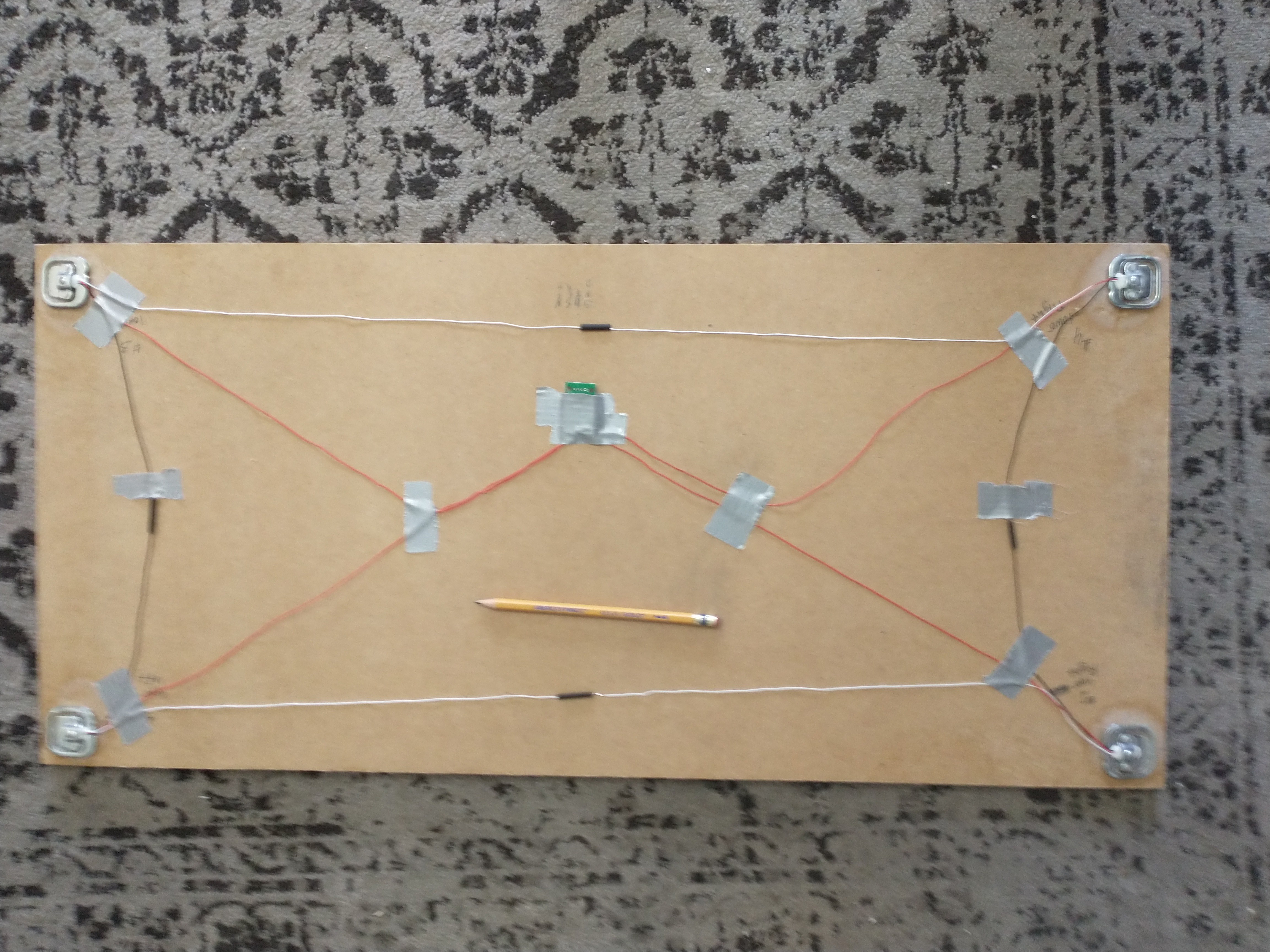
This is wiring is a 'wheatstone bridge" circuit for connecting the 4 load cells positioned on the board. The load cell amplifier in the middle has a 24 bit analog to digital converter that can report the readings from the load cells to a microcontroller.
![]()
This video shows the clearance of the scale, it's just high enough for the boards to not get in the way.
programming the scale is pretty simple as well, there is a great library that takes care of the hard work for you; it comes with a calibration script and plenty of other examples.
In the above video I zeroed out the scale with the grow rack on it, then calibrated the scale with a 5lb bag of substrate.
Summary:
I've created an accurate rough draft of the wireless scale that will track how much mycelium or fruiting mass is grown during a session. I need to add some code to the esp8266 for receiving and sending http requests to the raspberry pi via wifi/ or communicating directly via usb serial if it's plugged in. I also will be adding a small rechargeable battery circuit so that the scale will have power even when it's not plugged in, making the wifi capability practical. But for now I'm switching back to programming the MycoBox "enviornment manager" program, since all of the sensors and relays are now functional.
-
MycoHub wiring design consideration update
07/16/2021 at 15:22 • 1 commentIntro:
I initially started this project intending it to be just the 'MycoBox', a raspberry pi monitored and controlled chamber for spawning and fruiting. However, I soon realized the MycoBox is nearly a perfect bench-top space for including a complete mycology lab as well! So, my wiring design is in need of an update.
Initial Idea:
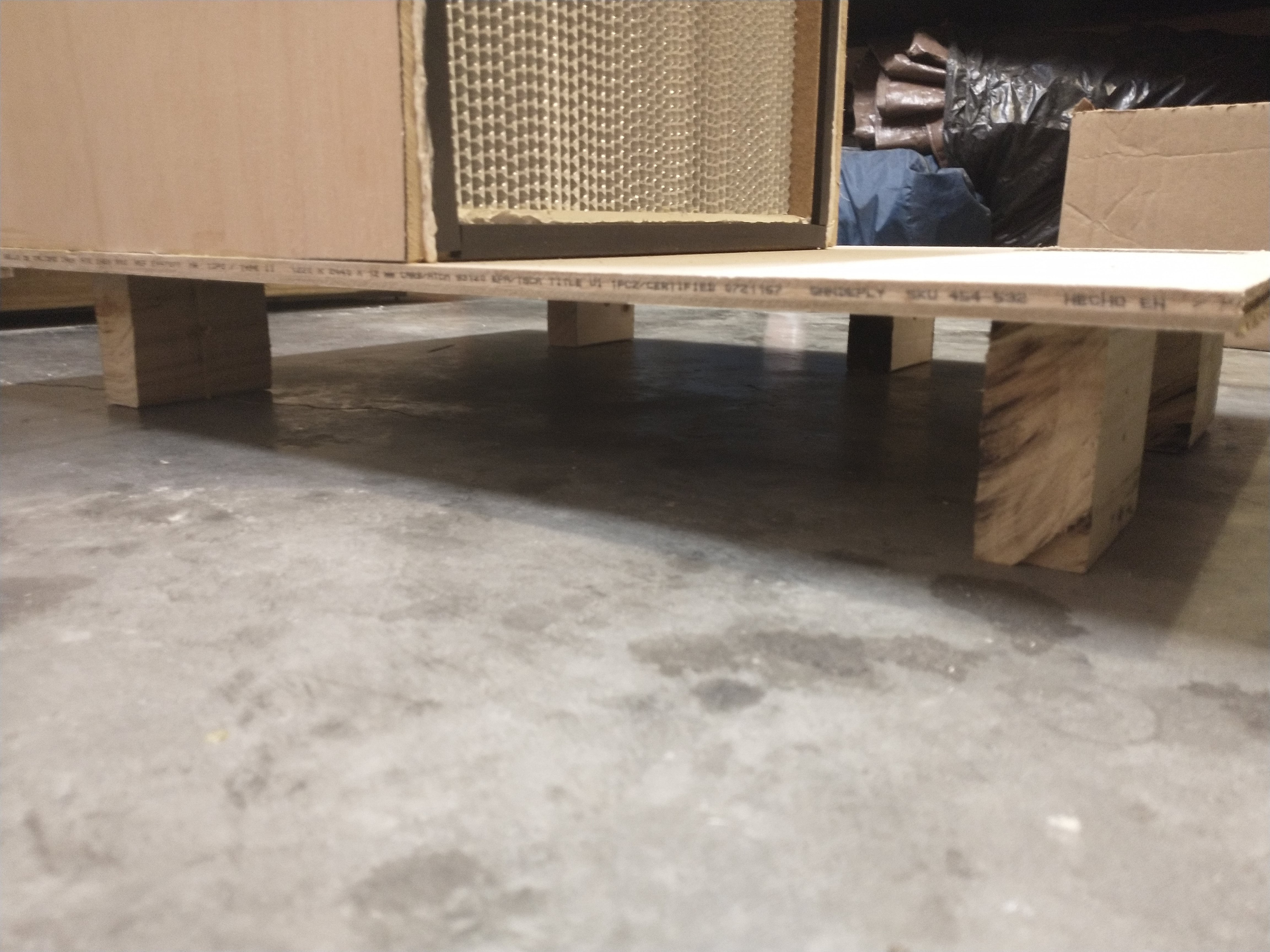
I like to keep data and clock lines from my controllers to my sensors as short as possible, as a best practice I think, so I intended to place the raspberry pi in an insulated box inside the chamber right below the sensor pole ( front door pole that holds the CO2, humidity, and temperature sensors).
![]()
![]()
This way I could run relay wires under the floor and over to the relay panel out of sight, and run a few data lines neatly up the pole to the sensors.
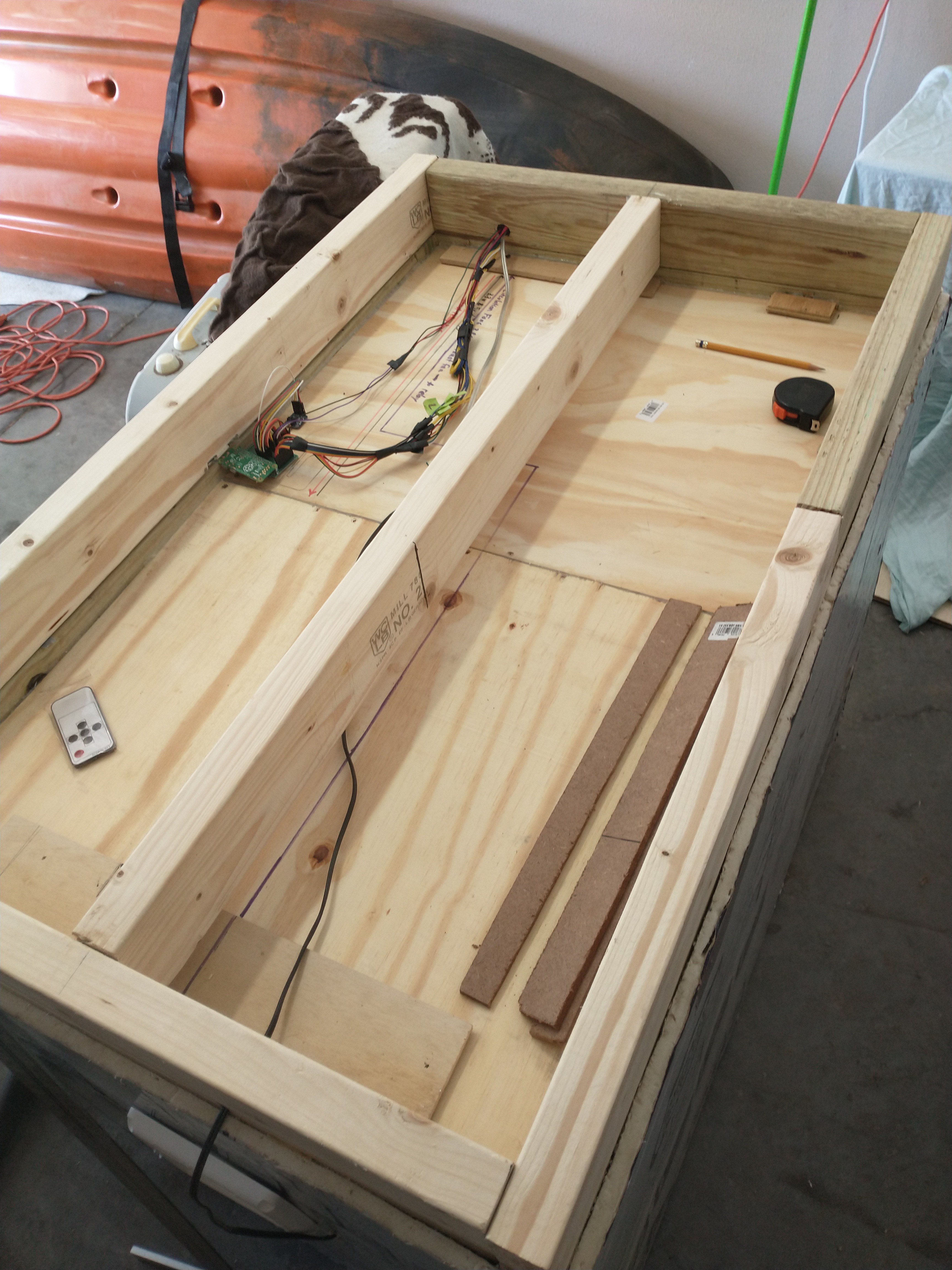
New idea & why I'm changing the design:
- I can keep the raspberry pi completely out of the chamber and place it in an air ventilated section above the MycoBox and below the MycoLab (components of the MycoHub).
- The MycoLab slides into place on top of the MycoBox and can easily be lifted and placed aside to access a very accessible electronics pan. I think this is just a nicer UX for anyone that may need to maintenance the sensors, or relays, or access the raspberry pi, or any other electrical wiring.
- It will also be easy to include wiring and control for the mycolab here as well
- when the MycoLab is seated into position on the MycoBox, it plugs into the power supply and control circuit
- I wanted to raise up the MycoLab a bit by rimming the MycoBox with 2x4 boards so that it's at a more ergonomic standing lab height (you could use a stool as well)
![]()
- The flat grey fan is my previous spacing idea, keeping the tray at 1.5" depth. However, I plan to raise the MycoLab up just a bit higher anyways, so now there's just a more generous amount of space to work with.
- The increased pan depth also gives more room for adding a nice thick, not thin flimsy, board for the bottom of this space and the ceiling of the MycoBox; which I think is better. Also a bit more room for any insulating/heat resistant layering I put down in the tray.
Summary: The Raspberry Pi will live above the MycoBox and below the MycoLab in a ventilated access panel for easy construction and maintenance, instead of inside the MycoBox chamber.
MycoHub
A comprehensive mycology platform; a clean box, a lab incubator, a "smart" spawn and fruiting chamber with online data tracking for research