Close
0%
0%

glo

A tiny programmable RGB LED based on Atmel ATtiny13.

Similar projects worth following
glo is a tiny programmable RGB LED based on ATtiny13. The idea is that it can
be a "smart" drop-in replacement for a regular LED. For example, the LED could
flash in a pre-programmed way, or respond to analog input on the GPIO pin.

Specifications:

- Atmel ATtiny13 (10M1 package)
- Common cathode RGB LED
- 3 Pins - VCC, GND, GPIO
- Standard 2x3 ICSP header (pads) for programming
- Can be programmed using a Pogo Pin programmer or equivalent

glo is an Open Source project and you can find the files here:

https://github.com/electronut/ElectronutLabs-glo

I have uploaded glo 0.3 gerbers to OSHPark:
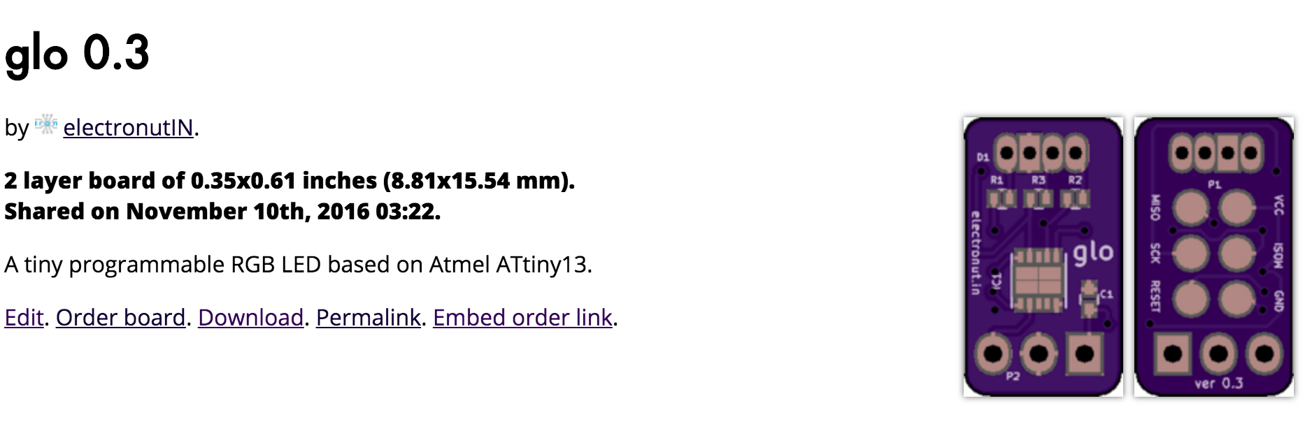


https://oshpark.com/shared_projects/Eu1TpIlK

Here's a video of glo in action:

For the curious, the red PCB is snapVCC, a buck converter regulator I crowd-funded successfully last year:

https://hackaday.io/project/6269-snapvcc

View project log

Enjoy this project?

Share

Discussions

ActualDragon wrote 11/10/2016 at 19:12 point

cool project, but what is the PCB on the 9 volt for?

  Are you sure? yes | no

Bill wrote 11/13/2016 at 21:40 point

I also think this is pretty cool. I'm guessing the PCB is a voltage regulator to provide 5 volts to the circuit, is that correct Mahesh?

  Are you sure? yes | no

ActualDragon wrote 11/13/2016 at 21:58 point

seems like more than that, and besides, you could just do that on the breadboard, or put the voltage regulator on the LED

  Are you sure? yes | no

Bill wrote 11/13/2016 at 22:25 point

What you say about using a breadboard mounted regulator is true of course. But if you look at the description and the schematic there are 3 connections to this module - VCC, GND and GPIO.  There are only two wires coming from the PCB on the battery in the demo, so I assume that they must be VCC and GND (and they are red and black too) .

This is what leads me to suspect that the device on the battery is a voltage regulator. Perhaps the  jumper on the board lets you select between 3.3 and 5 volts, if so it might be useful if you don't have a bench power supply.

But again I'm just guessing, Mahesh can fill us in on the details.

  Are you sure? yes | no

Mahesh Venkitachalam wrote 11/14/2016 at 00:37 point

Hi Bill,

The PCB is indeed a voltage regulator which uses a buck converter. It's actually a product of mine called snapVCC which was crowd-funded last year:

https://hackaday.io/project/6269-snapvcc

Regards

  Are you sure? yes | no

Bill wrote 11/14/2016 at 01:11 point

Hi Mahesh

Thanks for clarifying. That's a pretty neat voltage regulator!

  Are you sure? yes | no

Similar Projects

Does this project spark your interest?

Become a member to follow this project and never miss any updates