Close
0%
0%

New PCB For Calculator Watch

I like to call this my smart watch, as it can calculate numbers and show the time

Similar projects worth following
I found this calculator watch on aliexpress for under 3 Euros and intend to replace the PCB featuring an ARM chip, mainly to learn stuff. The LCD stays and I want to find out how to connect it.

Goals

  • keep the LCD and find out how to talk to it
  • make the PCB as big as it can get inside to maximize real estate
  • make it tell the time in 24h mode
  • add a pink backlight LED (or a color of your choice, maybe RGB?)
  • get IrDA on SERCOM1 working
  • get I2C on SERCOM5 working
  • use https://github.com/gregdavill/KiBuzzard/
  • get everything into Arduino somehow
  • personal: use more open source software and learn about ARM chips


LCD

currently the plan is to use an SAML22 chip, as it has an LCD controller inside

Watch

buy one here, they have 70k laying around: https://www.aliexpress.com/item/4001351603141.html

  • rev1

    davedarko11/16/2023 at 17:27 4 comments

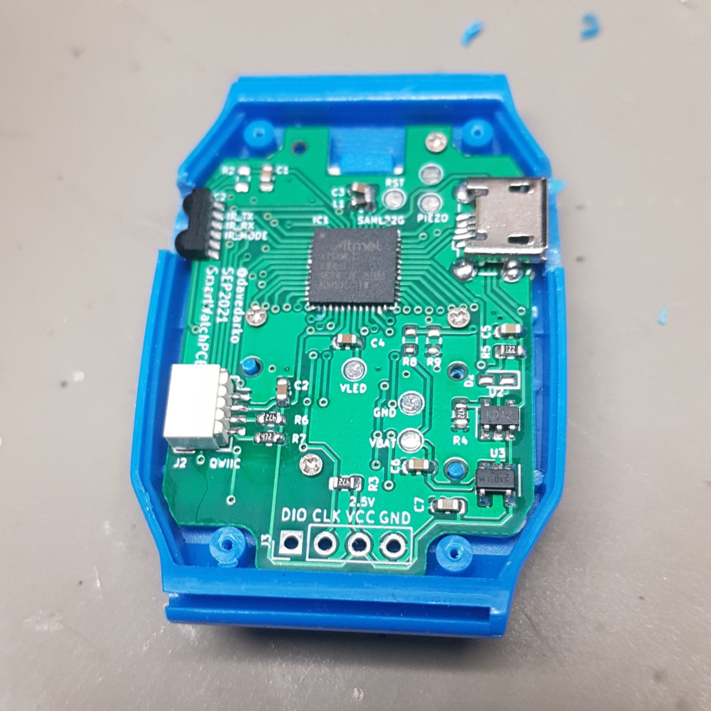
    The first version was doomed from the beginning, since I had no diodes on the keys. I also swapped the USB micro socket with a JST-SH socket and made a small adapter board instead. Let's see how far I get this time. 

  • ugh how did I do it again? LED's get to blink

    davedarko12/15/2021 at 20:58 0 comments

    This seems to be the setup for my controller and the chip, as the SAML22 works with the at91samd target.

    #!/bin/bash
    
    openocd -f interface/cmsis-dap.cfg -f target/at91samdXX.cfg
    
    # in new window
    
    openocd -f bootloader-sensorwatch_m0-v3.7.0-12-gf92e7dc.bin

  • First woopsie on the PCB

    davedarko10/29/2021 at 12:59 4 comments

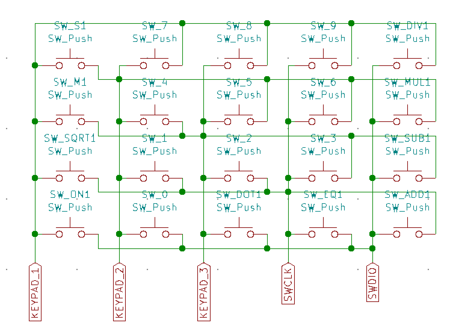
    By now I've realised that I forgot to add all the 20 diodes to make the charlie-plexed keyboard function. In the current arrangement there will be no way of telling if I have pressed the button connected to the 1-2 pins, or the 2-1 pins. 

    This basically made me choose between upscaling the SAML22 to the version that Joey Castillo is using for his amazing casio F91W replacement boards. I could also try to place twenty diodes all over the board. Or ten and do some crazy "check if both combinations are working or just one" firmware. In the end I used an IO expander that is dedicated to read keyboard matrices, got some TCA8418RTWR on aliexpress, as they're out of stock everywhere else.

    Soon I will try to get the UF2 bootloader running on the watch and then start programming it via the USB socket. First I need to cut out room for the plug though :)

    https://github.com/joeycastillo/uf2-samdx1

    Little side note: Joey will soon start a crowdfunding campaign with his awesome project, find it here:

    https://www.crowdsupply.com/oddly-specific-objects/sensor-watch

    More on the project on the blog:
    https://hackaday.com/2021/08/08/wristwatch-pcb-swaps-must-be-in-the-air/

  • Dipping my toes in ARM programming

    davedarko10/09/2021 at 12:45 1 comment

    So many things to learn are ahead! Thankfully there's a project out there, that is using the SAML22 for a watchproject for use with LCDs, the Sensor Watch by Joey Castillo. https://github.com/joeycastillo/Sensor-Watch

    On that github page Joey talks about installing the gnu arm toolchain from here[https://developer.arm.com/tools-and-software/open-source-software/developer-tools/gnu-toolchain/gnu-rm/downloads/] and run make in that one folder. On my mac (and probably every other computer) I had to add the toolchains path to my $PATH variable, like this:

    export PATH="$PATH:/Applications/ARM/bin/"

    Apparently openOCD is a thing people use to slap those sweet binary files onto plenty other ARM processors and you can get that over here https://openocd.org/

    To familiarise with openocd, I tried to work with some commands and get to know what's going on. I tried to list all possible adapters and see what's out there and if my programmer is on that list. The space between "adapter" and "list" is confusing openOCD, so be sure to use one of these working ways to write it: 

    openocd -c "adapter list"
    openocd -c adapter\ list

     I'm rocking this neat little CMSIS-DAP debug probe [https://www.tindie.com/products/zelin/pitaya-link-cmsis-dap-debug-probe/] that you can get over at tindie for a fair price. Arturo182 gave me the tip to buy this, when I was trying to update the firmware of the #Keyboard FeatherWing 

    One little thing that took me off-guard: the openocd works like a server that you connect to, but you first have to start it with the settings set to your target micro controller. Then you send the bin / hex files to the controller via a tcp or telnet connection. 

  • First boards ordered

    davedarko09/13/2021 at 12:06 3 comments

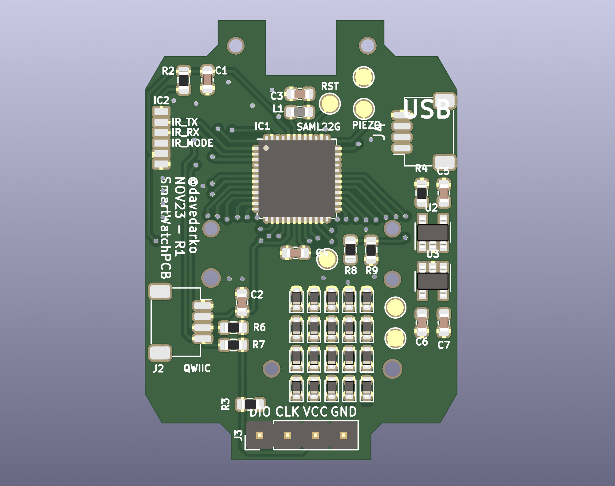
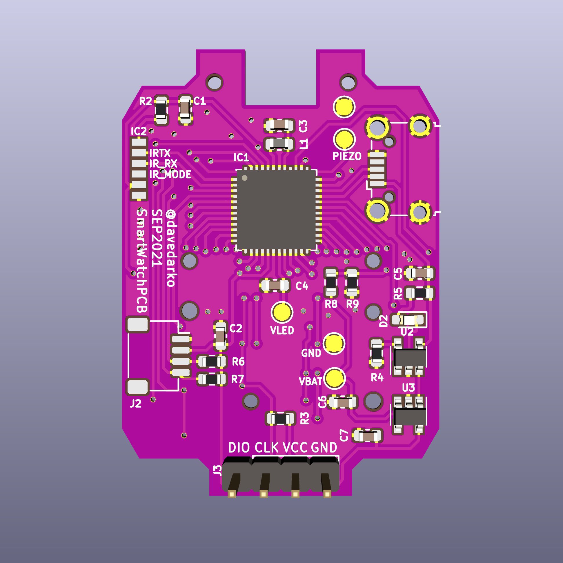
    After a longer break I managed to draw the symbols and footprints of the SAML22G and the IR transceiver module, so I would not have to rely on licenses of external sources. With that I was able to finalise a first prototype board and send it to JLCPCB for production. With the recent pink PCBs that boardhouses now produce I was very tempted, but I opted for a set of 5 green PCBs instead. I decided to run the board on 2.5V, which makes it easy for the AP2112K to work with the battery voltages of a LiPo battery, without running into dropout voltages first. There is some room and I'm tempted to add a footprint for a compass chip in the future, but I can always just connect to the QWIIC connector, as long as they are okay with 2.5V. Should have thought about that.

  • working in KiCad

    davedarko07/25/2021 at 12:31 4 comments

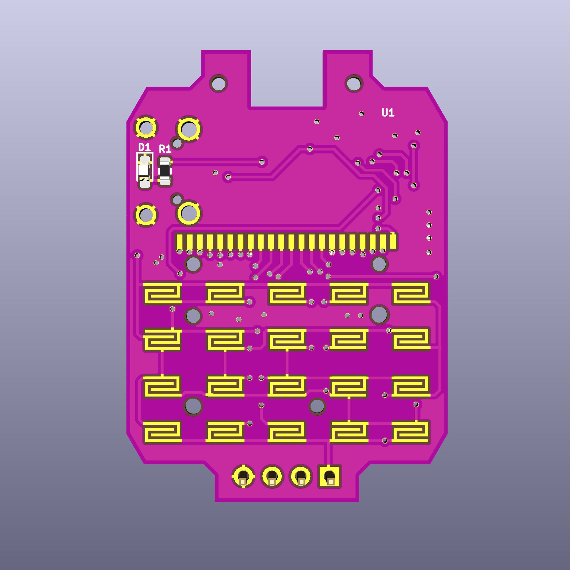
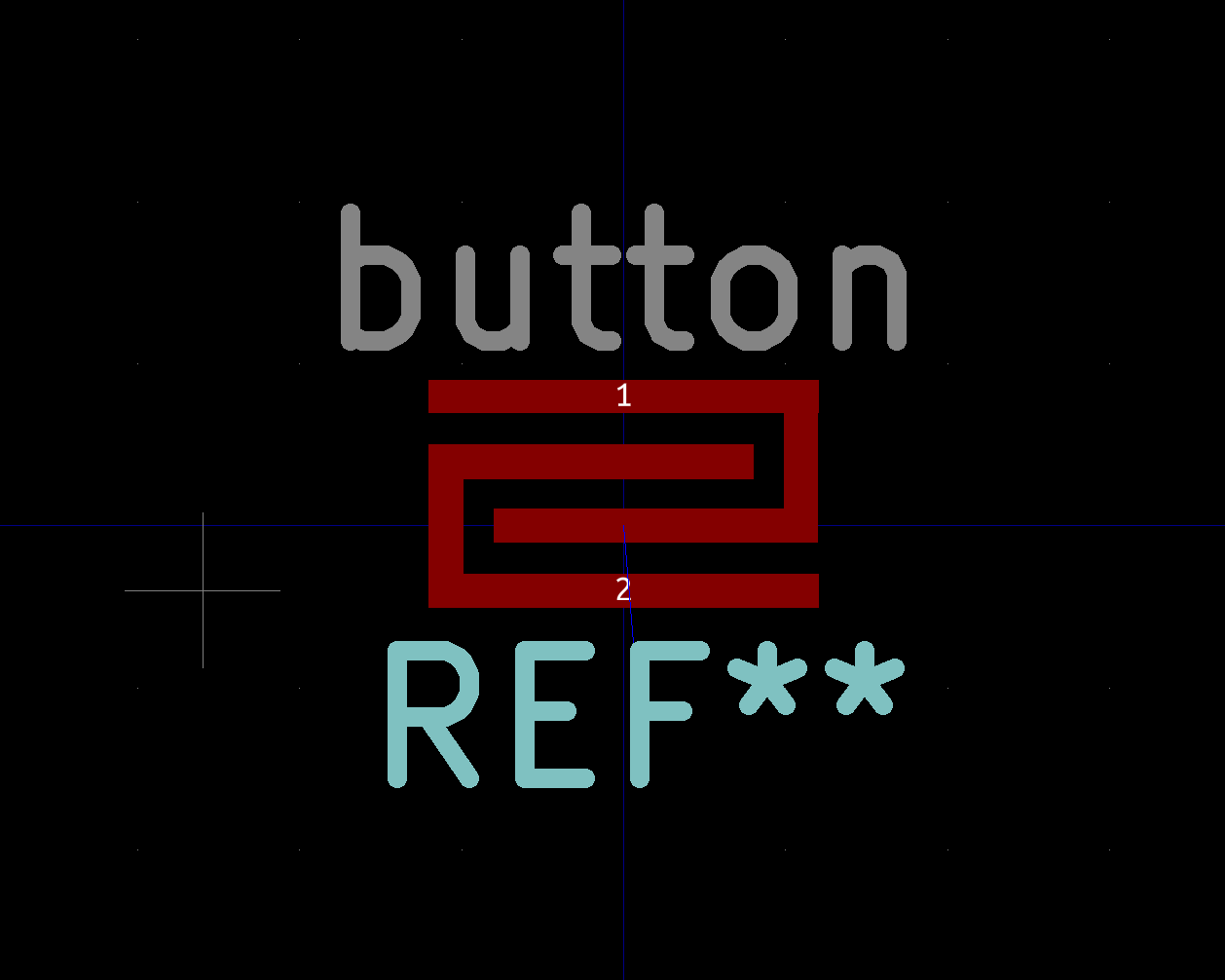
    The original footprint of the keyboard buttons comes in these interlocking C-shapes. New to KiCad I wondered if it would be even possible to generate something like this. Turns out you can create custom shaped footprints like this in the footprint editor. One catch, you have to work around a standard pad and add to it. At first I was drawing the complete shape and had a 2mm x 2mm right in the center.

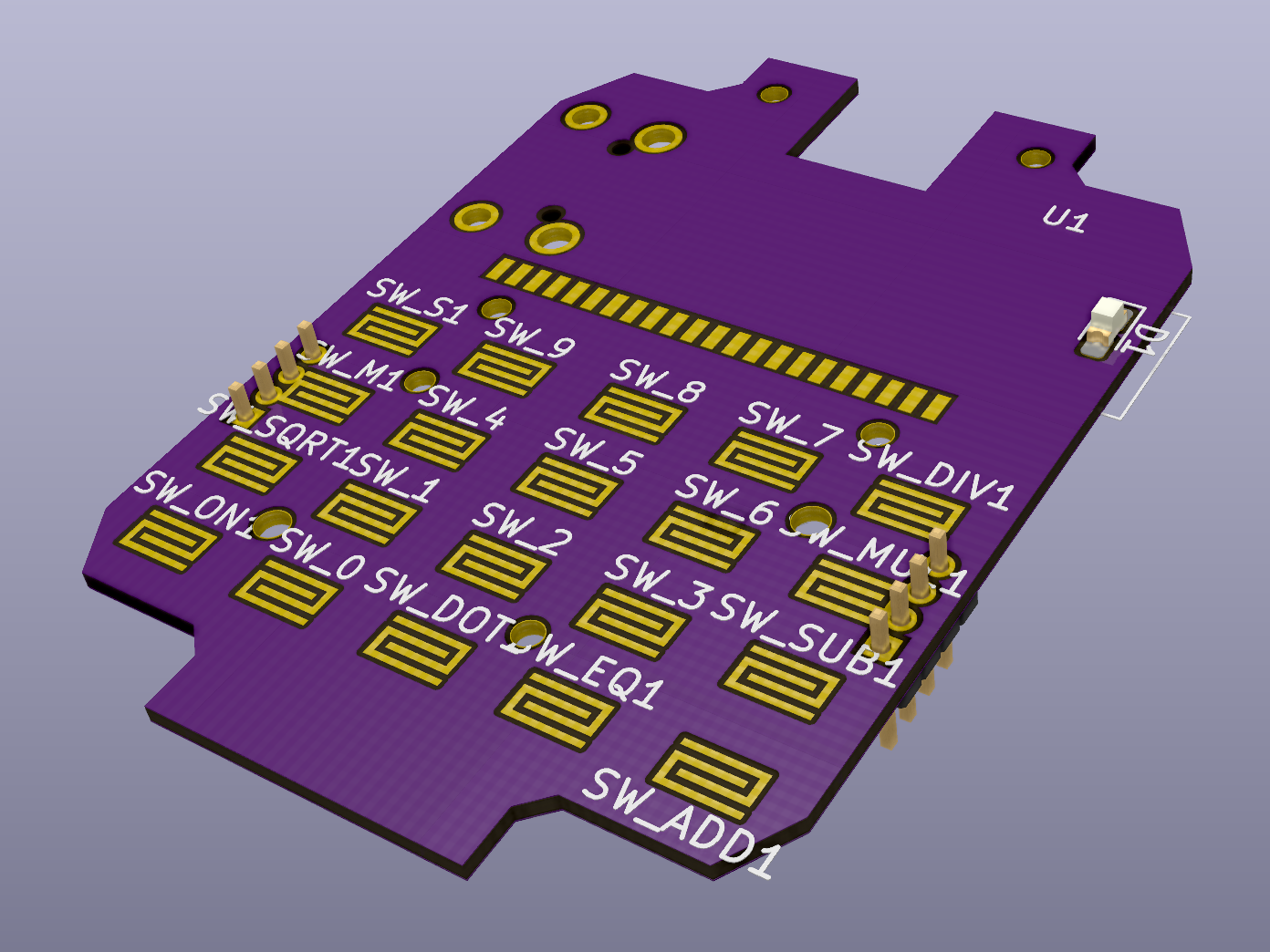
    I still need to design and replace footprints here and there, but I wanted to see some renders, so I gave everything a fitting part. The USB micro-B is a storage driven choice. Since all this is open source you're free to change it to whatever plug is to your liking! There are copper bits in the drill holes, I need to fix that.

  • progress on the schematic

    davedarko07/25/2021 at 12:17 3 comments

    To see what's possible to add to the project, I needed a pinout list. Sadly the datasheet has a single table with all (G) 48pin, (J) 64pin and (N) 100pins in it, so that the L22G pins are all over the place. I printed out the 3 datasheet pages and cut them down and glued them together to a single page. I then marked all the LCD pins, USB and SWD pins and took a look at what was left: 10 pins. With a keyboard matrix of 4x5 pins I would normally have to use 9 pins, but instead I will use charlie-plexing to scan the keyboard. I was told that I can also use the SWD pins for other shenanigans, so I used them for the keyboard matrix and was now left with 7 more pins!

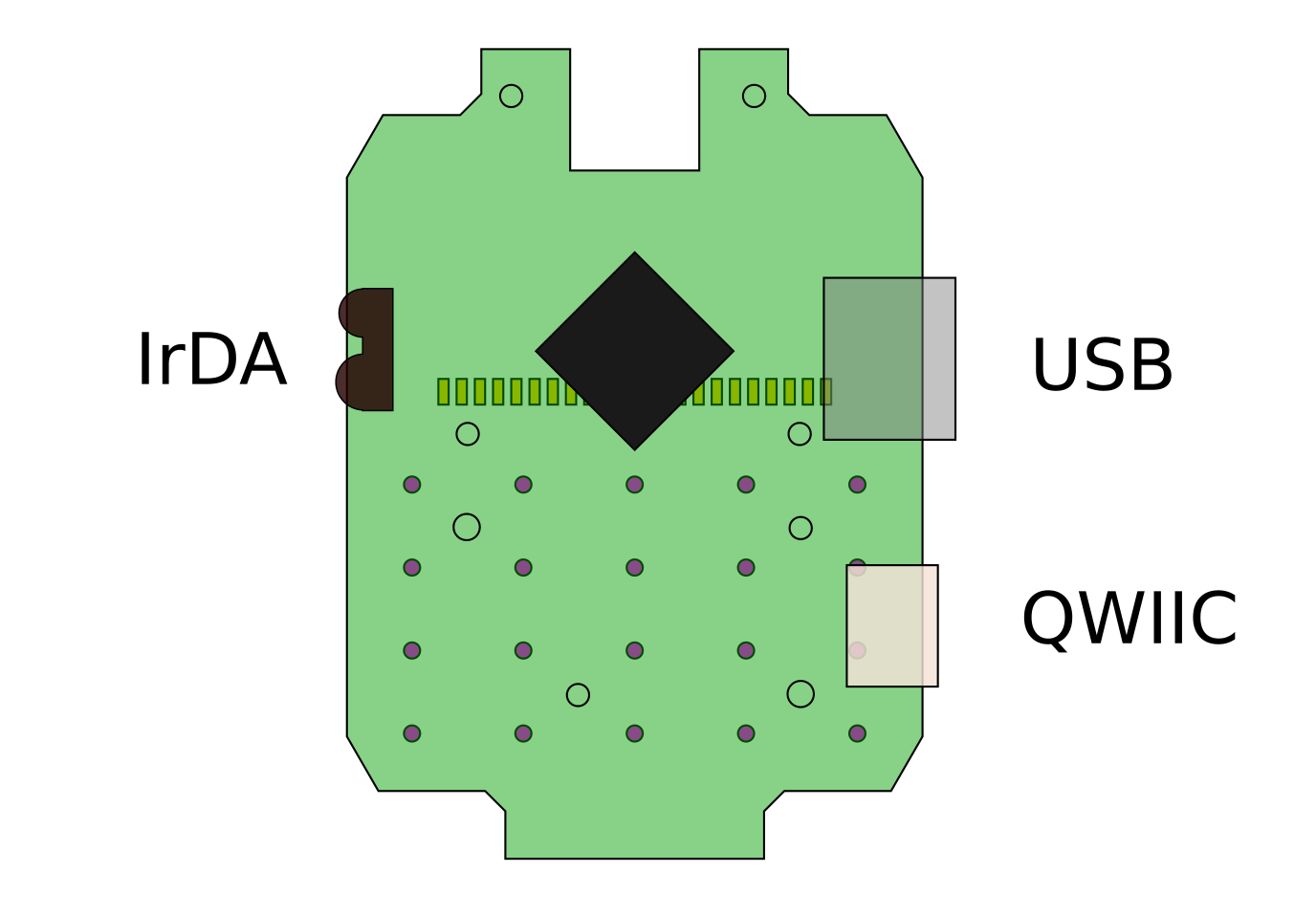
    For communication I thought it would be nice to have an Infrared setup. I might be able to run tv-b-gone on it or even switch channels, ha! The TFBS4711 seems like a good tiny candidate for IR communication, so I chose that to connect to the SERCOM1 pins plus an extra pin for the shutdown pin. It might take a while until I have that functional, as there are other things that I would like to get running first.

    There were two more pins of an USART interface free, so I chose SERCOM5 to be the I2C pins and connected them to a QWIIC connector. Might come in handy for controlling wearables in the future. All these addons including the USB connector mean the case needs to be modified.

    That leaves us with two more pins that will be used for the piezo buzzer and the LCD backlight LED. There's a steep learning curve ahead of me when it comes to the firmware and integrating everything into the Arduino environment.

  • ATSAML22 | hardware choices

    davedarko07/18/2021 at 08:51 0 comments

    There are different versions of the ATSAML22, for this purpose I have set my eyes on the ATSAML22G18A, it has the lowest pin count, meaning it's the smallest, while also having 256kB SRAM for programs. The amount of SRAM is probably not necessary in the end, but for developing it is good to know that you have enough space and can downgrade to reduce BOM cost. The chip has an integrated LCD controller with lots of options and 23 dedicated pins that are highly configurable - perfect amount for the 22pins of the watch LCD.

    Another way of controlling the LCD could have been using the very well supported Holtek HT1621 and a controller of your choice, like maybe an ESP32 or a nordic chip. An Integrated LCD controller can also be found in the Atmega169, but it's an EoL product and the datasheet from 2006 says "Not recommended in new designs".

  • PCB dimensions

    davedarko07/17/2021 at 18:57 0 comments

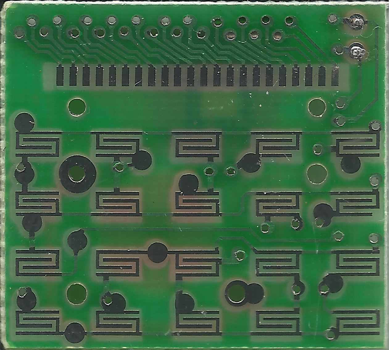
    To make a replacement PCB you first have to know everything you can about the old PCB. Looking for my scanner I found a different one and used that instead. It was surprisingly easy to just plug it into my computer and scan without installing any ubuntu drivers, nice. After some tweaks in GIMP I was looking at this, the important side of the PCB with SMD pads that connect the LCD and the button matrix.

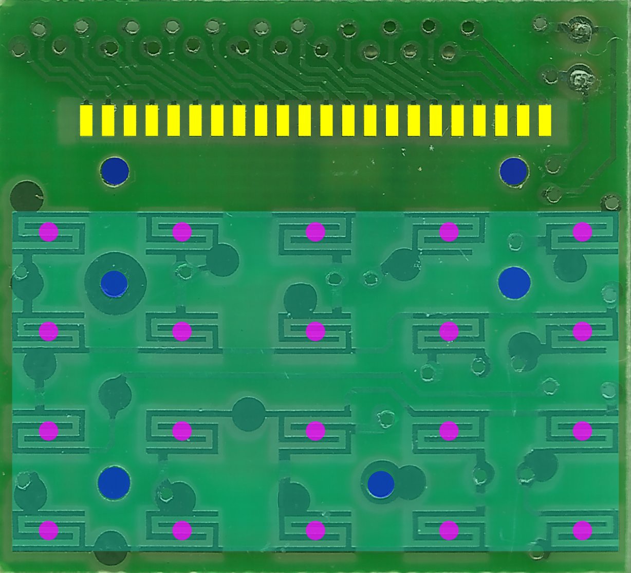
    The next step for me then was to import the PNG into inkscape, mainly to draw the new shape of the PCB and get all drillholes and button positions, as well as the LCD pads. The pads are spaced 0.9mm from each other. I learned that by measuring 18.9mm from first pin to last pin and dividing that by 21. Nice.

    There are 1.1mm, 1.2mm and something around 1.4mm drill size holes on the PCB, either for screws or mounting poles of the plastic case. After pushing things around and trying to find a center I ended up with this colorful layered image.

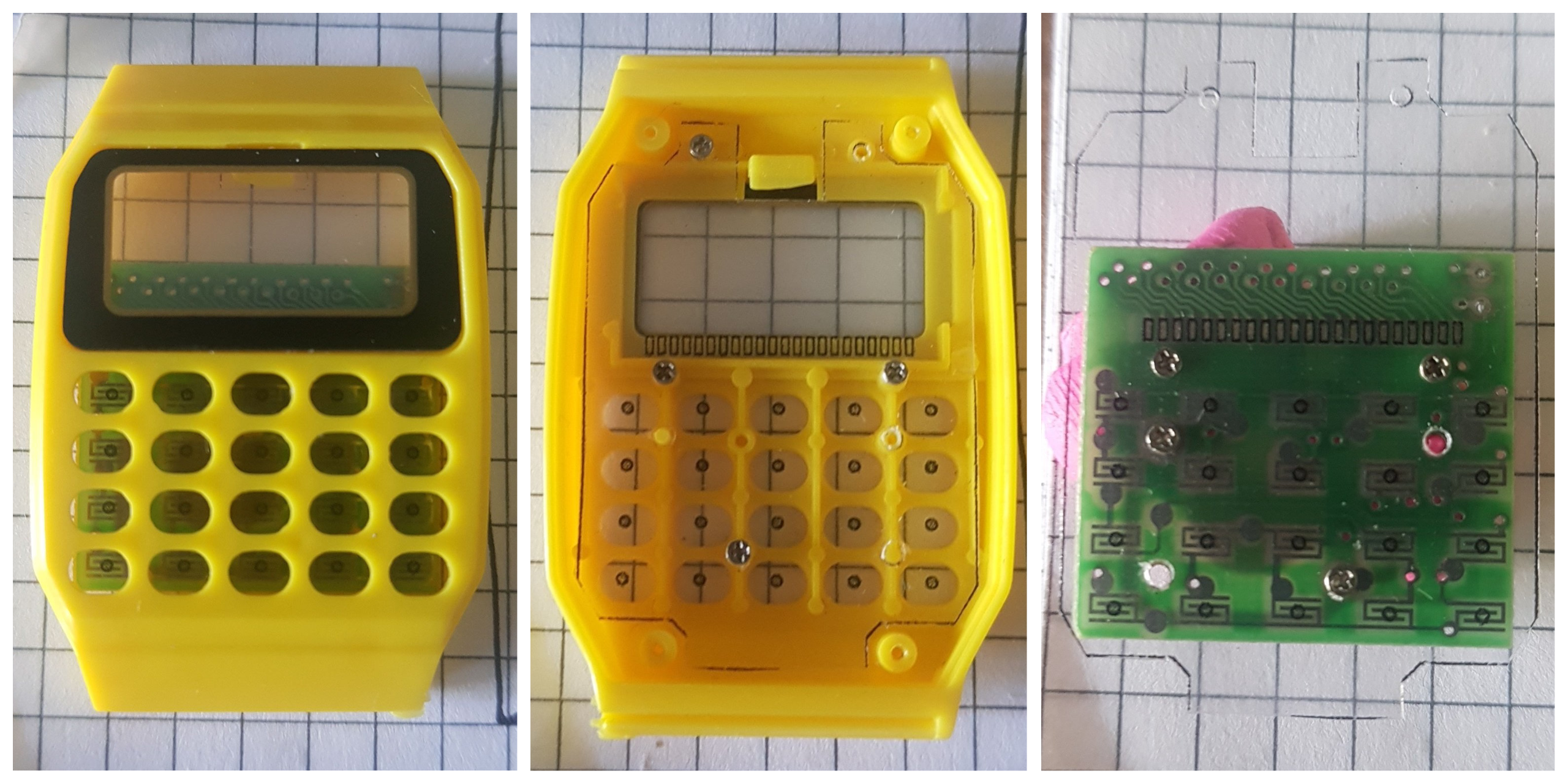
    I continued with importing a photo of the case internals, so I can draw a new PCB shape with more real estate, using what I can get. We definitely want to add a side glowing LED and there are some free screw-holes that we can use. To test the PCB dimensions and mounting hole positions, I printed only the contours of all the elements onto a clear overhead projector foil. It helps to have small drill bits around, to probe the hole sizes.

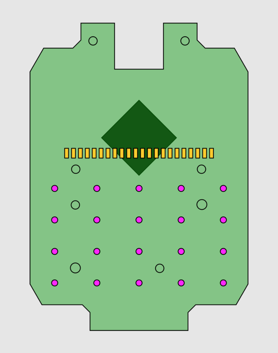
    Looks like the fit checks out :) Now I need to find out how to get that SVG into something that I can convert and work with in KiCad. Did you notice how many open source projects I've listed?

    This is what the PCB now would kinda look like. I might remove the LCD holding tap and close that top opening as it does not really seem to do anything. 


  • Pinout Of The LCD

    davedarko07/17/2021 at 18:21 0 comments

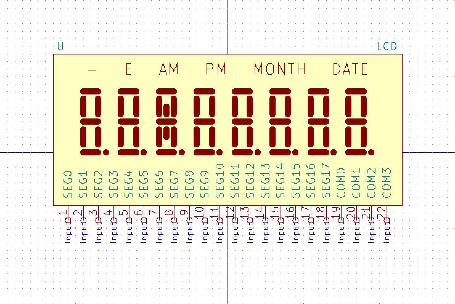
    The blob chip on the PCB is on the other side of the contacts for the LCD of the PCB, so there are 22 vias that I was able to sand and solder to. I've cut the connection of the chip, so I basically ended up with a breakout board for the LCD. Because of it's "capacitive" nature the display showed something just by connecting the positive pin of the power supply to a segment pin (voltage not important as there was no circuit completed). At least I think that's the reason. I guess everyone has taken apart an LCD calculator and was fascinated that it shows something just by you touching the pads or pins of the display. Anyways, thanks to this "trick" I was able to see that the 22 pins of the LCD are 18 pins for groups of four segments and then 4 of course for one of that activated segment. Thee pinout is super straight forward, as the 4 common pins are the last 4 on the right.

    Here's a screenshot of the KiCad symbol I'm working on right now

View all 11 project logs

Enjoy this project?

Share

Discussions

hkfairbanks wrote 02/20/2022 at 06:31 point

This is a really cool project. Are you selling these boards so we can build one with you?

  Are you sure? yes | no

Xasin wrote 02/10/2022 at 22:48 point

Hey - once you're done with this, PLEASE revive one of these:
https://twitter.com/xyster/status/1491838907738116099
This HAS to be the coolest, dorkiest version of a calculator watch that I know of

  Are you sure? yes | no

davedarko wrote 02/11/2022 at 09:42 point

well that's why the IR transceiver is in there :D

  Are you sure? yes | no

jonnyr wrote 02/07/2022 at 01:40 point

Is it possible to feed the time into an Arduino or similar board? So, it knows the time at power up.

  Are you sure? yes | no

davedarko wrote 02/07/2022 at 07:56 point

you mean like an RTC module? The only way I can think of is by reading the LCD display pins of the IC in the watch - not very practical.

  Are you sure? yes | no

jonnyr wrote 02/07/2022 at 22:29 point

You have a good point,; not practical indeed. I ordered a few of these from Ali express when I saw your project. One of million projects that I've started. I think I'll just stick with the RTC.

  Are you sure? yes | no

makjullie wrote 11/04/2021 at 08:44 point

Any time I post an image of one of my PCBs, I generally get a remark or two about the "space slug" drawing...https://nethercraft.net/nether-portal-calculator.php

  Are you sure? yes | no

Hemal Chevli wrote 08/05/2021 at 12:35 point

I saw a similar project on twitter, try checking it out https://github.com/joeycastillo/Sensor-Watch/tree/main

  Are you sure? yes | no

davedarko wrote 10/29/2021 at 12:48 point

Joey was the one suggesting the SAML22 to me, thanks! It will be heavily used to make this work somehow :)

  Are you sure? yes | no

Mao Wang wrote 08/04/2021 at 16:25 point

Looks like a really nice project. Have you considered using the QuickLogic EOS S3? It has the ARM M4, direct connectivity to a microphone so you could add voice trigger or commands and an eFPGA for even more features in the future. And the dev tools are all open source.

  Are you sure? yes | no

davedarko wrote 08/04/2021 at 17:59 point

I have not, it sounds like a very cool chip though. I'm normally just tinkering with 8 bit chips and the SAML22 comes with an integrated LCD controller, so I'm pretty set with learning new things using an ARM processor already and then the challenges of getting everything to work in it self.

  Are you sure? yes | no

Mao Wang wrote 08/04/2021 at 18:07 point

Makes sense. Good luck with the project. the casio databank watch was a dream watch for me when I was a kid, and it's so cool to see it in action.

  Are you sure? yes | no

Mike Szczys wrote 07/30/2021 at 15:38 point

This is such an awesome project. I love the constraint of the board size... not too small but certainly a challenge. And the reverse engineering of the screen was a great read!

The part that always fees so difficult when I look at doing wristwatch designs is figuring out how to power them. Looking forward to details on how you take on that challenge.

  Are you sure? yes | no

davedarko wrote 08/01/2021 at 20:42 point

Aww, thanks :) I'm not so sure myself about the powering part, I might get away with using a coin cell, as the LCD and the SAML22 are not using that much power. But coin cells feel wasteful, so I want something rechargeable. 

  Are you sure? yes | no

sunny wrote 08/03/2021 at 07:20 point

spuer cap?

  Are you sure? yes | no

Ken Yap wrote 08/03/2021 at 07:38 point

If you can achieve the multi-year life of a CR2016 in my ancient Casio wristwatch, that's good enough.

  Are you sure? yes | no

Guy Dupont wrote 08/04/2021 at 16:00 point

I recently got some 3.6v rechargables that have a CR2032 form factor. They're only 70mah (compared to typical ~240mah of normal CR2032) and I haven't tested them yet... but they appear to exist!

  Are you sure? yes | no

sunny wrote 07/18/2021 at 03:30 point

looks nice

  Are you sure? yes | no

Similar Projects

Does this project spark your interest?

Become a member to follow this project and never miss any updates