 Ben Lim
-
1Buy BOM items
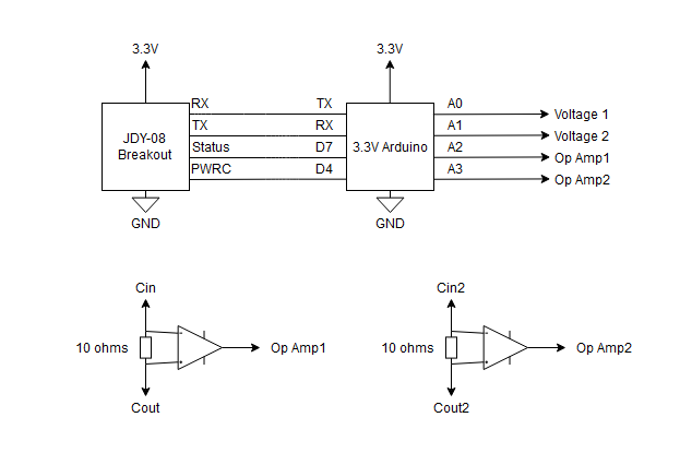
Insert the JDY-08 breakout board into the breadboard. Connect the TX, RX, 3.3V, and GND lines.
-
2Breadboard devices
Connect the circuit as indicated above. The inputs to the system are Voltage 1 and Voltage 2, (Cin,Cout), and (Cin2,Cout2). -
3Solder the Current Sense Amplifiers / Connect the current sense module
Solder the current sense amplifiers onto the breakout board and the male headers
-
4Upload Test Code
Upload the sketch named: "test_connections.ino" in Arduino. It should return "Success" in the Serial Console. This means that the JDY wireless module has been successfully reprogrammed.
-
5Upload Main Code
Upload the sketch named: "main.ino" in Arduino. It should start returning comma-separated lines in the Serial Console. This is the module sampling its outputs.
-
6Breadboard the power circuit
-
7Optional: Add a switch
-
8Capture data
Using the provided App or script, start to capture data. Remember to adjust the MAC address in the script for the MAC address of your JDY-08 module.
Simple, Compact Wireless Measurement
Measure, probe, and monitor voltage and current remotely!
Discussions
Become a Hackaday.io Member
Create an account to leave a comment. Already have an account? Log In.