The next version of the board is a 17mm x 30mm board that has the following improvements:
Precision voltage reference - no matter what the input, there will be a reliable reference
Change of current measurement IC - now it can measure from -0.1V to 30V.
Addition of Hall Effect sensor
The Hall effect sensor is meant as a tool to wake the device - since it is so small now, it can easily be used as a monitoring device for another circuit in a semi-permanent or permanent installation. With the Hall sensor, it can be used to wake the device remotely for measurements on a as-needed basis. Since the addition of the High Voltage Element, I've not found a reason to use it, so I might remove it for something else.
Do you have any ideas about what other features that might be interesting to add? Let me know!
As part of the ongoing development, I wrote some lines of code that enables low power features to extend the run time of the device.
Hall Effect Sensor - this is good as a wireless button to trigger the module
EFM8 Snooze Mode - When the EFM8 goes into Snooze mode, it stops code execution and turns off all clocks - this drops power consumption from about 5mA to 30uA.
Bluetooth Module Sleep Mode - When the Bluetooth module goes into sleep mode, it draws 830uA, down from an average of 9mA @3.3V
This cuts down power draw from 14mA to 1mA, approximately 14 times less, which extends the runtime of the embedded device.
This is just the low-hanging fruit however. Further energy savings can be gained from the Bluetooth module by putting a transistor in-line with the power supply, the BLE unit can be turned off completely. This means that the device can be put on standby for 180 days on a coin cell.
Finally, if the Hall effect sensor circuit is designed so that it cuts off power from the coin cell completely, then the device can be on standby for a long period of time.
Now that you have your whole analog system set up, what do you actually reference to when taking measurements?
Previously I didn't really care about how I was taking measurements because the ADC reading was always good enough - but now when it is actually used to convert into an actual voltage reading, precision and accuracy is incredibly important.
For the EFM8, by default it takes the VIO as the reference. This is great if you have a clean consistent voltage each time, but in this circuit, it is coming off a step-up voltage regulator, it can vary from 3.28 to 3.34 volts. Now that is problematic because the ADC uses this as reference voltage.
So for example if your reference is 10V, and you get 10 counts, then it is 1V/count. But if you set the reference to 9V, then it is 0.9V/count. But since you only get counts in your firmware code, so the same count would report a different voltage.
While trying to determine if I could control the output, I realized that this was a solved problem for EFM8 - just use the precision voltage reference!
It works superbly, but the only problem is that because I don't have it broken out, I need to solder a tiny bodge wire to a QFN pad....
To really realize the dream of being able to make these throwable micro-multimeters, it should be able to run off a tiny tiny power supply. That for me would be a CR2032 battery.
At 3V there is a a peaky spike of 25mA, if we want to be really pessimistic, we would only be able to get 40% capacity out of the 225mAh battery, which is 90mAh, which works out to 3 hours under constant load.
But the average draw is 13mA, which works out to about 75% of the rated capacity, 170mAh, which works out to approximately 10 hours. The actual time of running this device should then fall between 3 to 10 hours.
One way to extend this is to include a hall-effect sensor that can be used to wake up and sleep the module - this would be useful when you have no access to the module - think about when it is in an enclosure.
For power consumption, the device draws 48mA on average at 1.2V and 15mA on average at 3.3V
For a small AAA battery that is rated for 1000mAh, that means that it can last about 20 hours on continuous broadcast. I think that's pretty respectable especially if you can turn it on and off.
The parts are here and testing has begun! Unfortunately I made a mistake and it took me a few hours to figure out why my part was not responding: I didn't connect VIO to power - so that's what you see with the little botch wire there.
Unfortunately I'm still having trouble with programming the EFM8, and I think that has something to do with my rework, even though it looks good to me. As far as I know, the EFM8 only requires power and debug to be connected in order for it to be programmed.
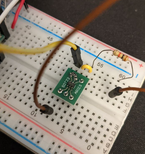
This is a MAX9938 NanoPower Op Amp being tested. Because I didn't want to make a whole new circuit just to test this, I decided to use a breakout board for an SOT23 footprint, and then soldered a 0805 5R6 resistor across the terminals. It is put in series with a 1k resistor, and the output was 0.923V. I measured the resistance across the terminals of the current sense resistor and it was 5.7 ohms. The voltage is scaled by 50.
Calculations
V = 0.923 V / 50 = 0.01846 V
V = IR
I = 0.01846 / 5.7 = 0.003296A
Given that voltage is 3.3V, and measured resistance is 983
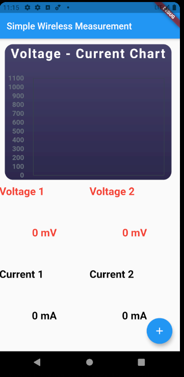
Here is a first look of the Android app. At this point it has not connected to a device yet, so no data is being displayed. It is written in flutter, so I expect that it can be converted to iOS and Android once I am done with it.
I think it makes sense to go with a phone app to display the data because it is a screen that we carry with us at all times anyway.
The next step is to show it working remotely over an SSH connection.
 Ben Lim
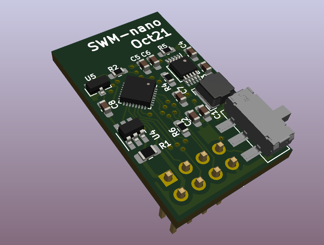 The next version of the board is a 17mm x 30mm board that has the following improvements:
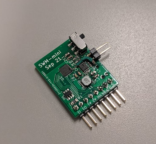
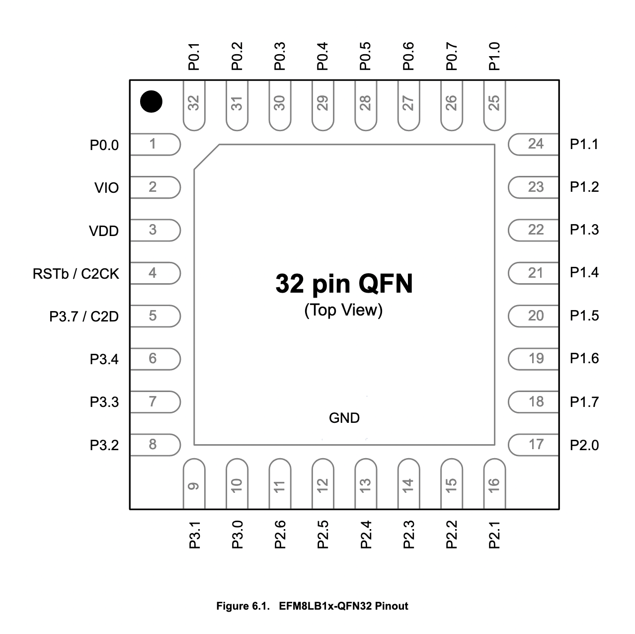 Pinout for the EFM8 QFN32 IC
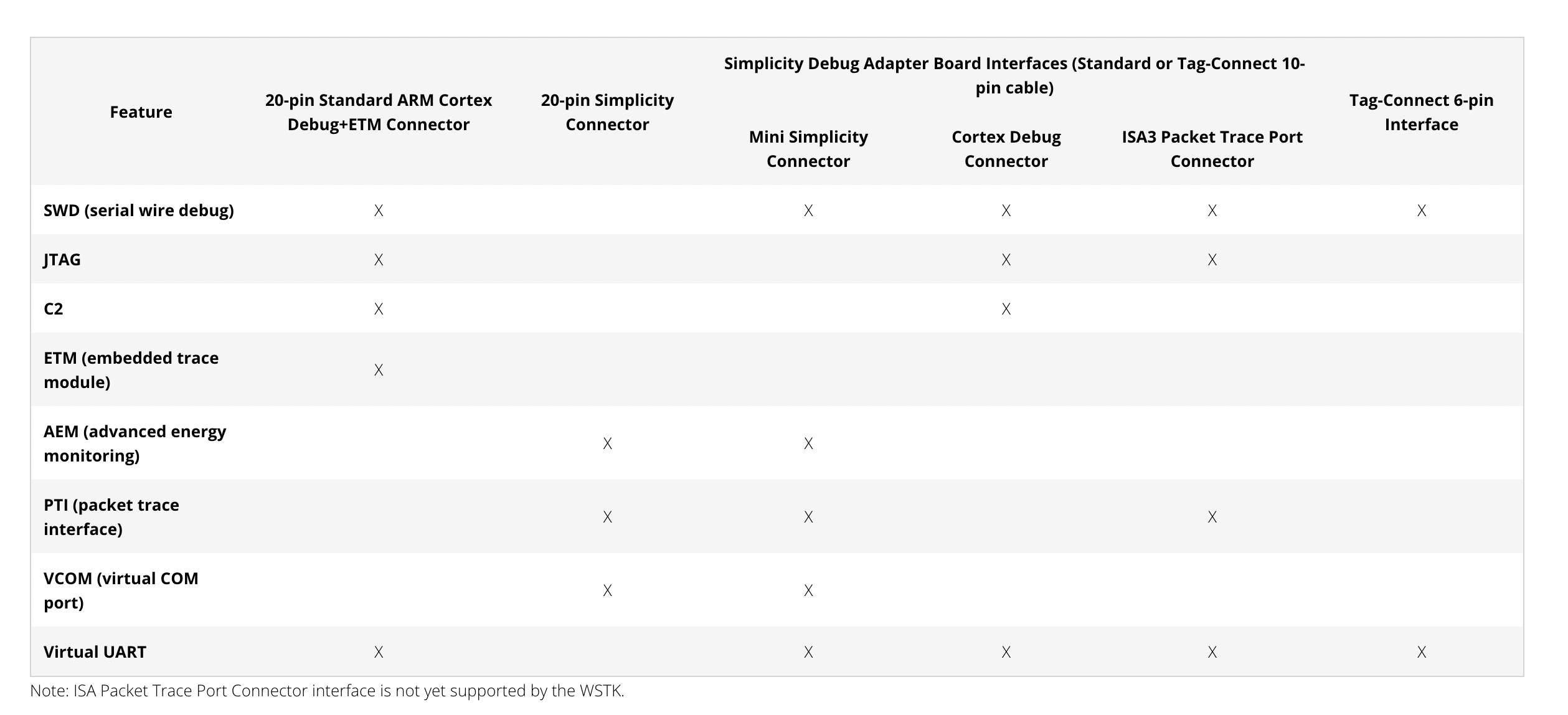 Pinout available on the debug adapter
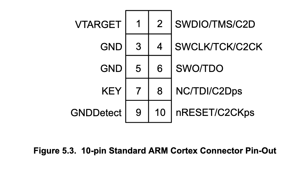 Connection reference
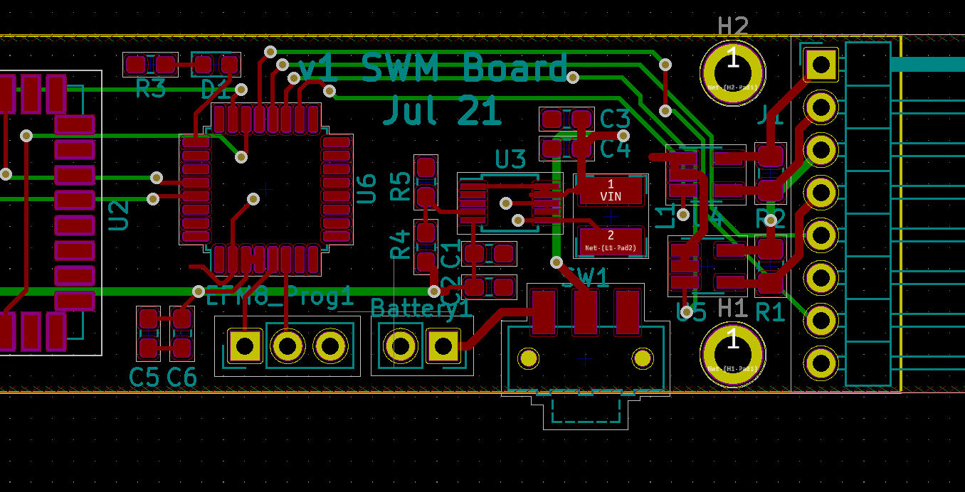 Schematic reference
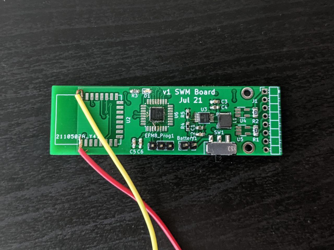
 The script is hosted at the project's Github