 vincentmakes
Axis modifications
The first step was to take pictures, disassemble the device and refit the new axis together.
From my measurement, and using the two belts initially purposed for the 2s plus version, I determined that the X axis should be 420mm and the Y axis will be 800mm long.
For the axis, I will use V-Slots from OpenBuild in 20x20 and 20x40 sizes. I've tried using regular I-type aluminum profile but they really don't fit.
It was fairly easy to install those back together and the next step was to lengthen the cables.
Neje originally uses a knitted sleeve to hold those together and it's great for the small version but then the cable are raising quite high in folded position when the Y axis is fairly long.
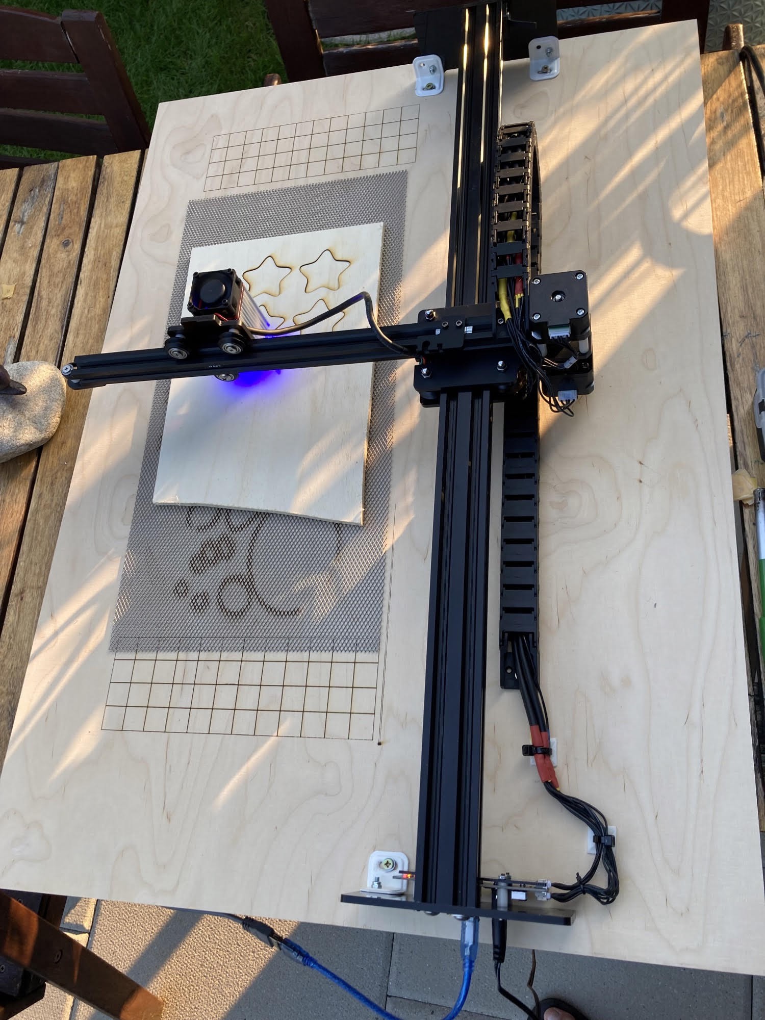
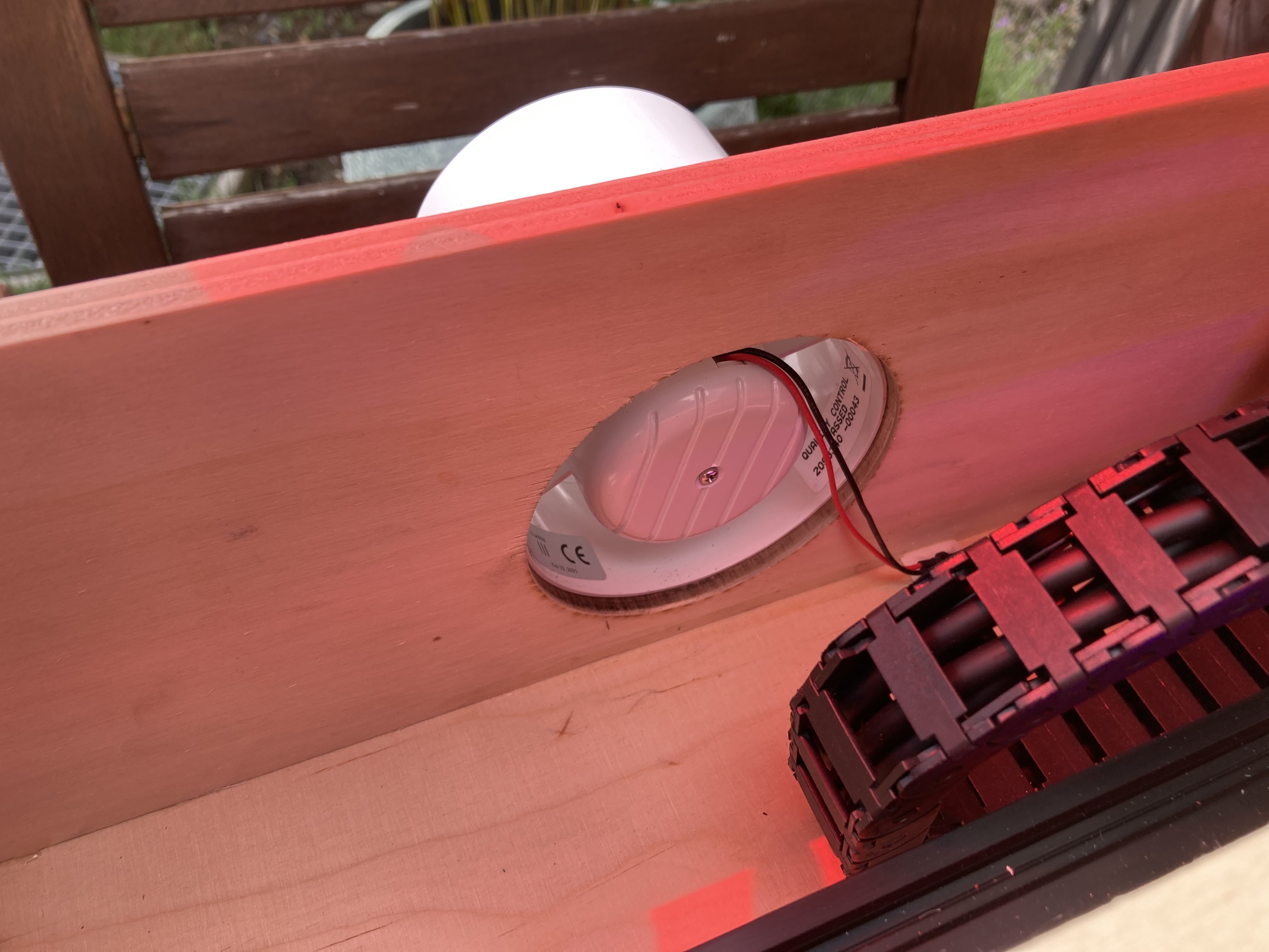
To avoid that and in order to build a low profile enclosure, I decided to use 15x20mm drag chain. It fits perfectly around the device. The only caveat with this drag chain, is that I can no longer slide materials fully underneath the device but that's mitigated by the large Y axis.
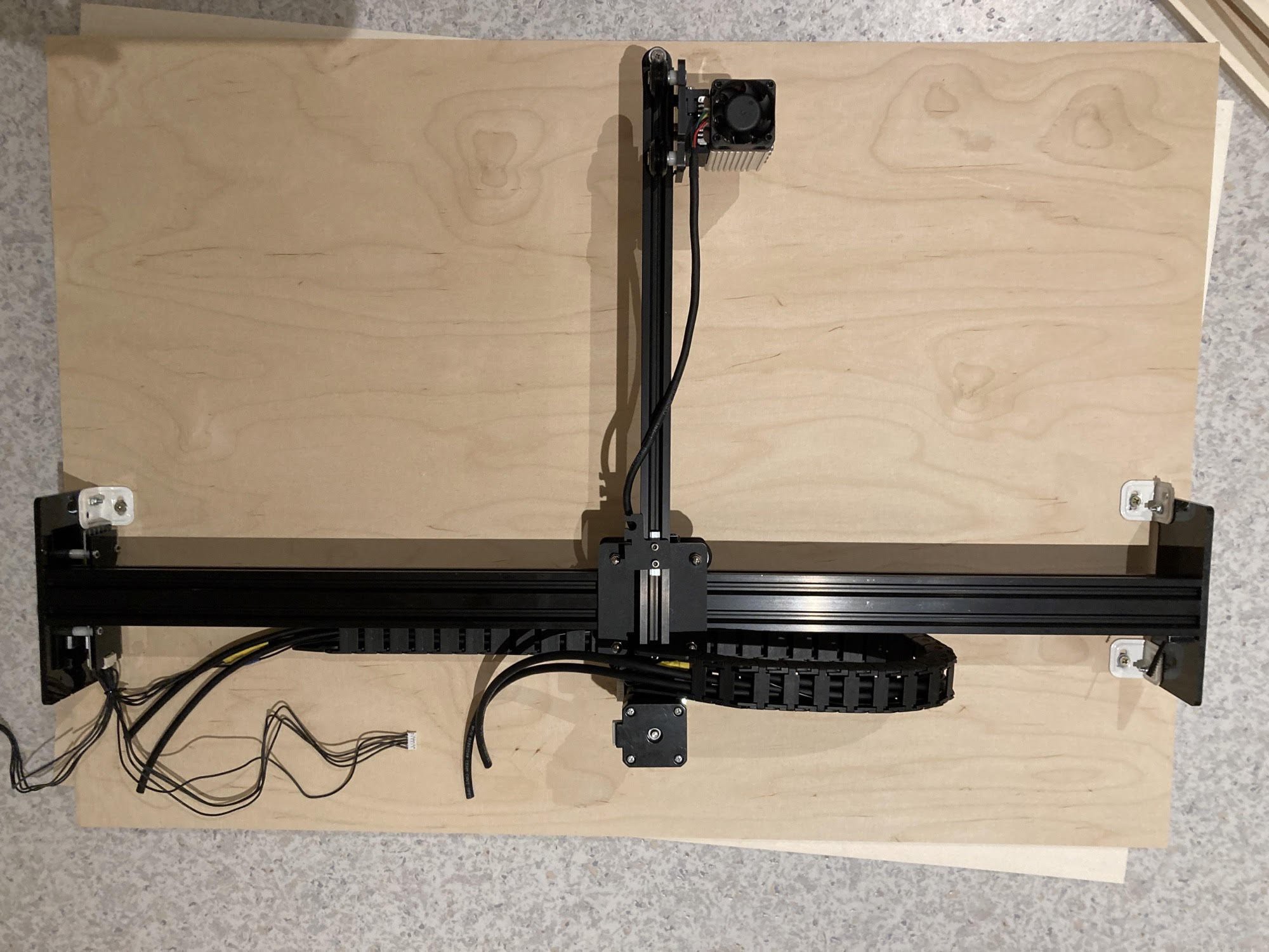
For stability purpose, it's important to secure the device to the board on the 4 sides. I've later change those above to the smaller aluminium brackets from Openbuild.
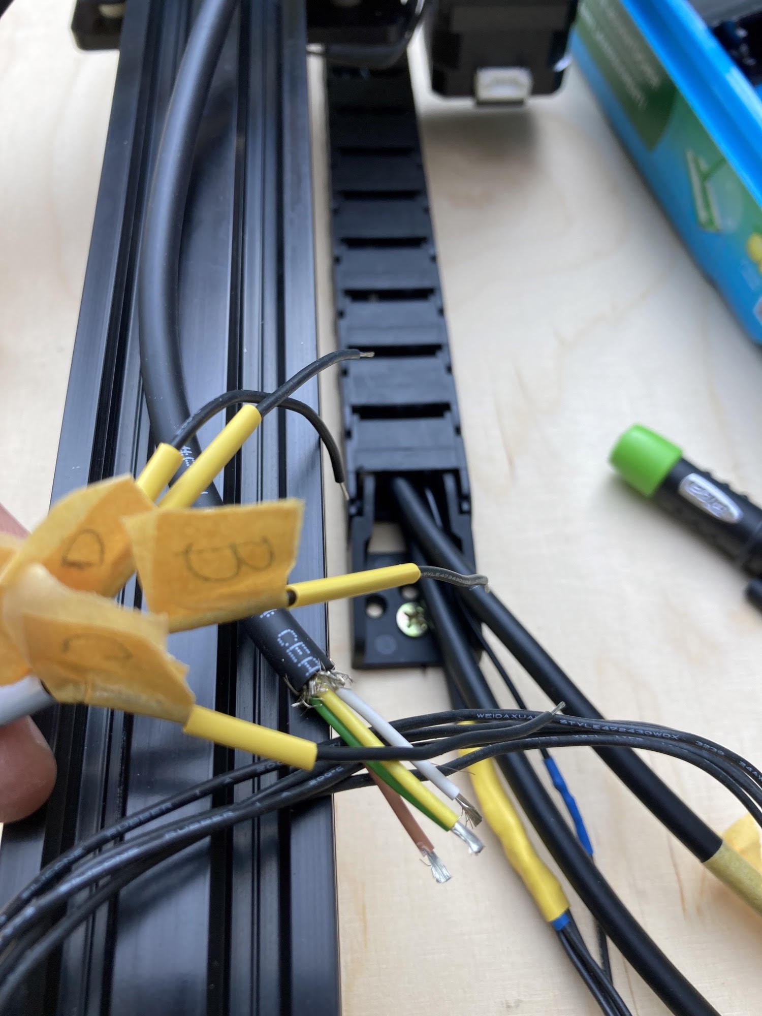
To extend the cables, I used a bunch of 4 wires mic cable: it's very flexible and meant to be bent. I've used an extra single cable for the connection to the laser underneath as this plug has 5 wires. The cable to the laser module is just long enough provided that the cable holder is adjusted.
The re-wiring is a rather tedious process, especially that the original cables are all black: I labelled the original cables, cut them in half, took note of which color matches which letter, and re-soldered everything back, making sure to work on one connector at a time.
Software Setup
Afterwards, it was time to test it. It's important to note that the Neje software will still work as per the regular 2s version which means the working area will remain 170x170mm and there's no way to change that. However this can be changed when using Lightburn.
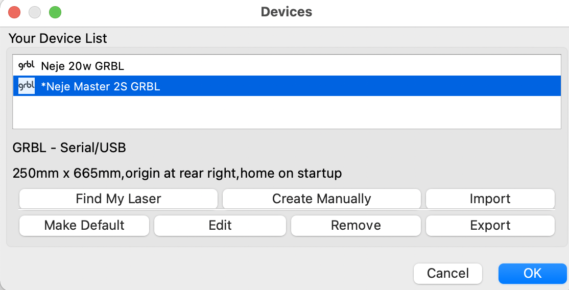
There are 4 paramaters to be changed:
1. In GRBL settings: X max travel distance=665mm and Y max travel distance=250mm
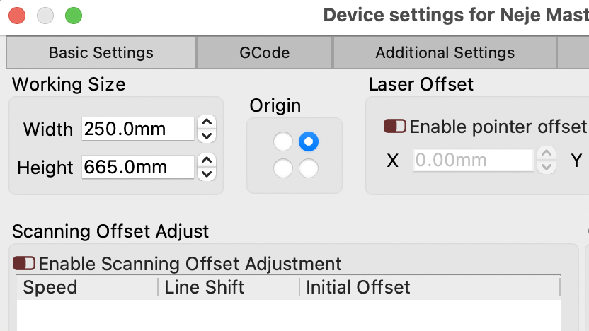
2.In Lightburn device settings : X and Y working area (665x250)
It took me some time to figure it out but the X and Y axis are not in the direction I thought they would be and I ended up with a "heightwise" setup. Here's how it looks like as well as a screenshot of the parameters.
I'm pretty sure I could go 5mm further in each axis however I kept some security margin
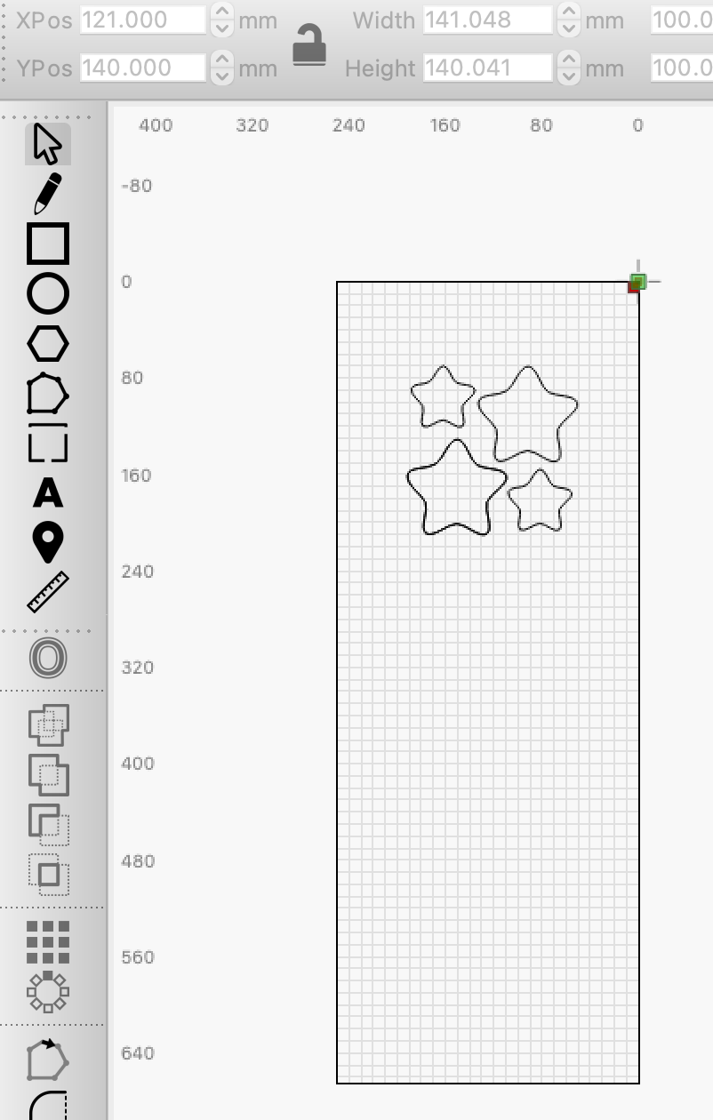
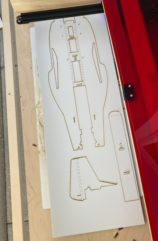
Here's a first test
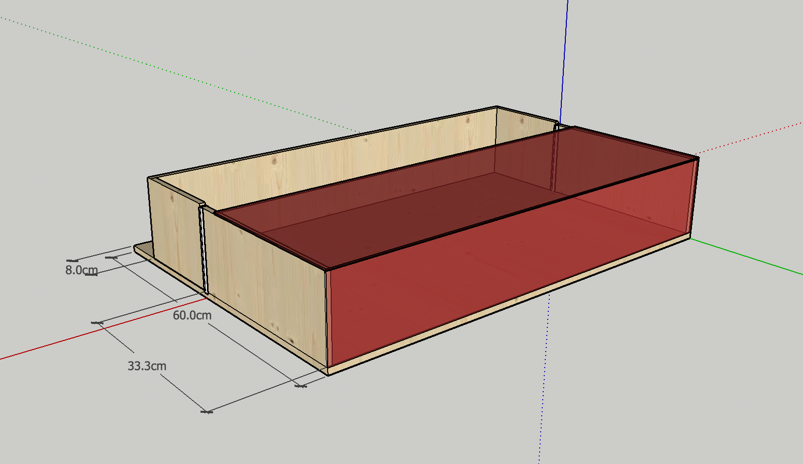
New Enclosure
The enclosure includes a 12V 100mm air extractor
I did a quick modelling in Sketchup
And here's the real thing
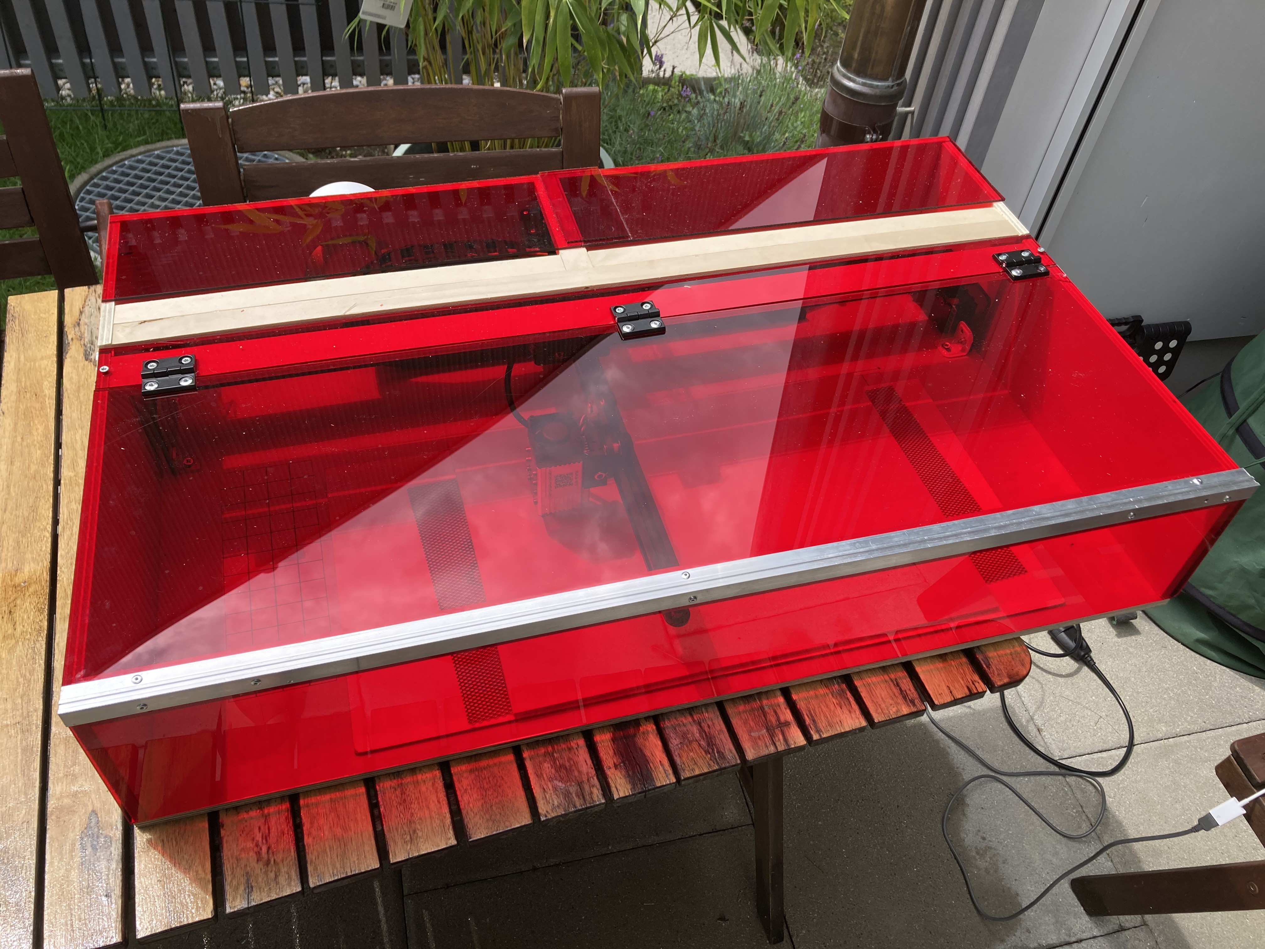
The air extractor works fantastic !
 The front has hardly any burnt mark


ho, i have same engraver, but i need to expand to 400mm x 400mm. Is it possible with this construction? I'm afraid if it will work when the laser is supported on one side. Thank you for answer:)