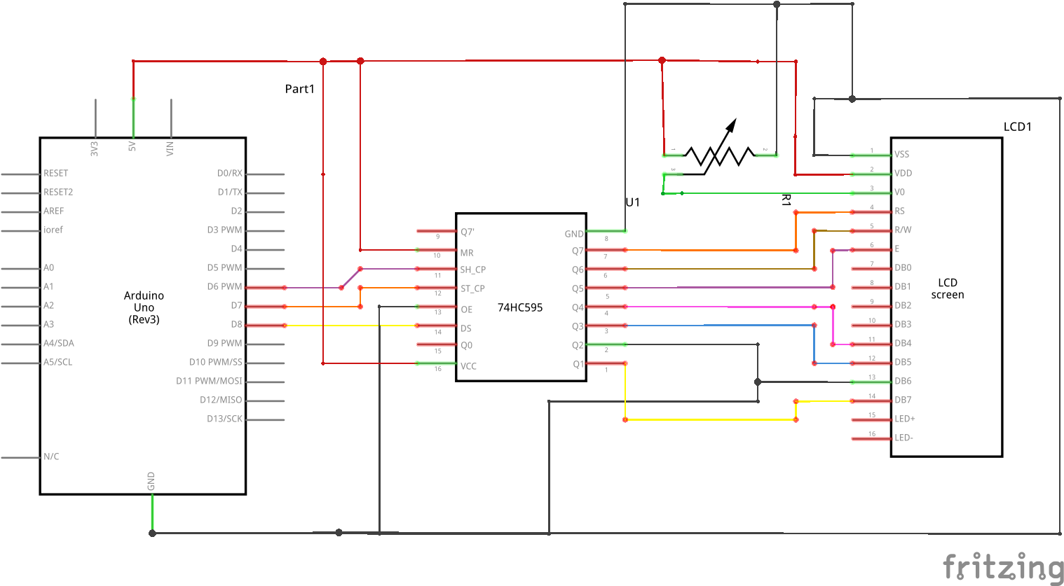
Sometimes the best way to create something is recycling old components giving them a new purpose.
During the pandemic I had to face a problem with one of my projects, I needed to display numerous pieces of information on an LCD display but I hadn't an I2c interface shield and I couldn't use a large number of pins to drive the display, so I searched online and I found some interesting solutions.
After developing a prototype I decided to write down a detailed guide.
Following this diagram can seem very complex for a beginner, but you need only to pay attention to the pins and their position (if you prefer you can also download the file with the diagram).
2
Build up the tin maze!
Following the path described in the diagram connect the jumpers to pins using the soldering iron, if you are a beginner you can use also the breadboard.
At the end of this instruction you should have a structure very similar to a maze.
Like this...
Remember if want to manage the output cables in a more ordinated way you can use also JTS connectors like these
connecting the jumpers to their pins.
3
Test your prototype!
Now your prototype is ready to be tested, so connect it to your microcontroller and run this script always paying attention to the connections
A "graphics card" this is not =) It's an interface adapter, serial interface to parallel. If you were to make a circuit that'd take a custom protocol of some sort and then convert it into what HD44780 displays understand, it'd be more comparable to a graphics card!
The schematic connects Q4 to DB0, but it should connect to DB4. It also connects DB6 to GND, where it should connect it to, apparently, Q2. Also, VDD on the display is +5V and VSS is GND, not the other way around - possible that your schematic will destroy displays?
And a 100nF capacitor between VCC and GND, close to the shift register, wouldn't hurt =)
This is my first article on hackaday, so I hope that these instructions can help someone and that were all clear and correct.
PS: probably the word "graphic card" in the description is incorrect but I like the idea of considering this shield as a graphic card, INVIDUINO got it?
A "graphics card" this is not =) It's an interface adapter, serial interface to parallel. If you were to make a circuit that'd take a custom protocol of some sort and then convert it into what HD44780 displays understand, it'd be more comparable to a graphics card!
The schematic connects Q4 to DB0, but it should connect to DB4. It also connects DB6 to GND, where it should connect it to, apparently, Q2. Also, VDD on the display is +5V and VSS is GND, not the other way around - possible that your schematic will destroy displays?
And a 100nF capacitor between VCC and GND, close to the shift register, wouldn't hurt =)