 Charitha Jayaweera
-
1Design a Model in Solidworks
I assume that anyone who is reading this already have a robot arm designed in Solidworks. The solvers that are available in MoveIt! is mostly supported with 6 dof robot arms. Therefore, I’ll be simulating a 6 dof arm for the sake of simplicity. Model is below.
![]()
-
2Installing the Solidworks URDF Exporter plugin
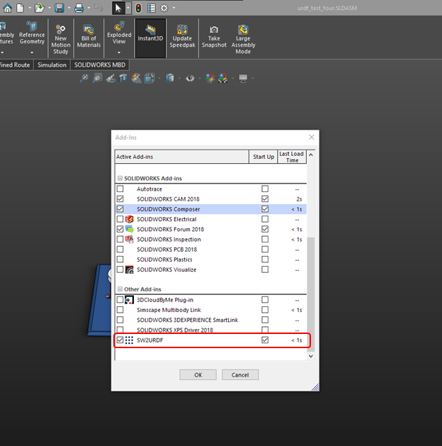
To begin with, The Solidworks URDF Exporter plugin has to be installed in Solidworks. Download the urdf exporter here. Close any solidworks windows that are open, and install. Open solidworks add-ins and activate the URDF Exporter
![]()
For some versions, the exporter will be on File>Export as URDF and for some it will be in Tools>Export as URDF.
-
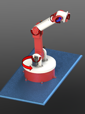
3Identifying the joints
I have modelled a simple, small 3D printable robot. And the end effector is an open end at the moment.
![]()
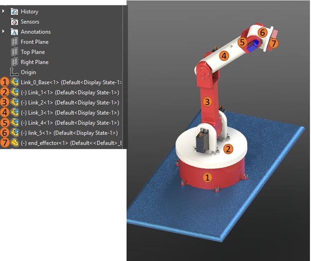
The 6 joints are visualized in the picture above. It’s generally good design practice in a design of this sort to use different subassemblies for each link. In this case using different subassemblies for each link in the assembly is a must. The design tree should look something like this.
![]()
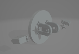
As you can see each and every link has its own subassembly. If you are using a subassembly, make the subassembly rigid. But in my experience, it’s always best to convert those subassemblies into part files. The URDF converter is still not perfect and it gives out some unusual errors. There is an unusual problem where the parts in the subassembly would float once it’s converted to URDF shown below in the figure. So, it’s best to convert the subassemblies into part files.
![]()
-
4How to correctly mate the joints in the Solidworks
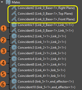
Since all the joints are revolute joints, in this case only mates that is utilized are coincident and concentric mates. The base joint, you could either make it fixed, or you could constrain it to the assembly planes with coincident mates (utilize the main planes in the base link). See the figure below, the Mates section in the design tree.
![]()
There are 3 coincident mates for the base link’s planes with the assembly planes (Yellow box), and after that, its 6 concentric joints and 6 coincident joints for each of the joints made by each of the links. You can observe the relationships between each of the joints in the image above. It’s a 6 DOF robot, hence, 6 joints (usual naming convention goes 0–5 though). After mating all the components, we have to then think about the color. In my experience, if it’s a part in the assembly, the URDF will take its appearance given in the part level. Therefore, after you have converted all link subassemblies into part files and assembled, Add appearance to each joint part in the assembly. The only downside to this is that each link will only have a single color. But you are welcome to play around with this by adding colors in the assembly in the feature level.
-
5Generating the URDF files
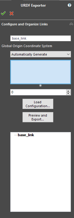
In my Solidworks 2018 SP 0.1, it was in the Tools>Export as URDF and for some versions, it’s in File>Export as URDF. Either way, it should give you a property manager window as below.
![]()
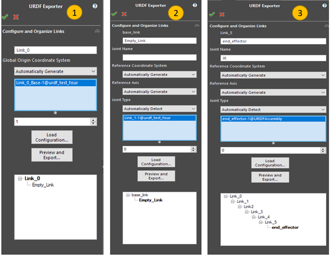
As it is apparent, all the subsequent joints after base are dependent in base movement, and all the links after link 1 are dependent on base and link 1’s movement and so on. It’s an open kinematic chain. Therefore, we need to define that in the exporter. The different steps would look like this.
![]()
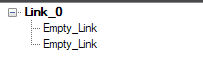
What we are doing here is defining the relationships between the components. Therefore, as you can see in 1, I’ve given the name Link_0 to the base and selected the part/subassembly of the base in the assembly. Just click the base in the model and it will identify. Then we have to select the number of child links the base has. And there is only one child link since this is a kinematic chain, therefore, it entered as 1. When you select that a child entity of the Link_0 would appear below. If you select 2 (which would be the case in a two-wheel car), it will be something like this.
![]()
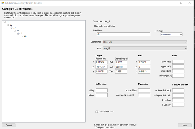
After you click the child link, you will see the property manager window change into the 2nd window above. It’s the same as the one before, name link, select the model and select the child links. Only new thing would be to name the joint. All the subsequent windows for all the links look the same and the final window after entering the last link, would look like the 3rd window in the figure. You can see the kinematic chain and the general relationship between the links in this window. Once you are done, click the preview and export button. This will generate the reference geometry that is needed. Like the coordinate systems and the rotation axis. It after generation, it will generate a window “Solidworks Assembly to URDF Exporter” like this.
![]()
This window will generate the URDF. But, before that, we need to check some things. So, minimize this for now
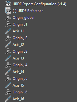
There is a convention that we need to follow when using MoveIt! and ROS. Check this ROS official guide’s section 1.1 to know about the convention more. But basically, it says to orient the Z axis up and the X axis in the front direction (this would be the direction the link 0 would be facing in the instance the Joint 0 angle is 0). If you look at the coordinate systems and the axis generated by the URDF Exporter, it would something like this.
![]()
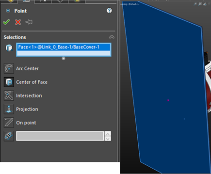
The Origin global defines where the robot arm would be placed in Rviz/Gazebo in its global coordinate system. In Solidworks, this automatically aligns with the master coordinate system of the assembly. Generally, I prefer the robot to be in the center of the simulation environment. To accomplish that, the origin of the assembly should lie in the center of the base frame of the robot. But more often than not, it usually doesn’t. Therefore, we need to move the Origin_global of the URDF model to the center of the base. To do that, we need to project a point using the “center of face” method (or the method that suits your model) of projecting a point as shown below
![]()
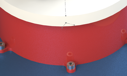
This is where I want the origin of the Rviz/Gazebo environment to lie. Create that point, and edit the feature of the Origin_global point and give the point that we created as the point of origin for the coordinate system. Before that, remember to move the point we created above the Origin_global in the design tree. The position of the coordinate system is done. Now the orientation. We can use the edges in the model to define the directions of the axis. But, the URDF generator generates a sketch which looks like below, and using that for coordinate system reference would be easier and would be without errors. Defining just the origin would be okay for now. But we can play around with the coordinate systems and properly define the initial position of the robot arm
![]()
After adjusting the coordinate system, check the axis are aligned properly with the revolute/prismatic joints, then close the dialog box that appeared and it will ask to save the changed configuration, which should be a resounding, “yes”.
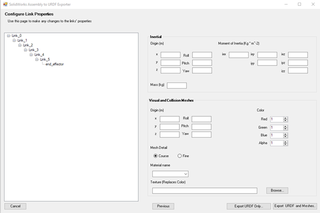
Then, start over with the URDF exporter, do not change any of the settings, and same as before, click on “preview and export” to get the “Solidworks Assembly to URDF exporter” window. Since this is a beginner tutorial, we don’t really want to change anything here at this point. Click next and you will get a window like this.
![]()
This will show the inertial data of the link, collision data and the textures. But we don’t want to get into this at this point. Simply press Export URDF and Meshes. And it will give a save dialog box. And it will take the name of the assembly as the name xxxx.SLDASM. Erase this. And replace it with something without numbers, dots in the name. you can use underscores. Ex: robot_arm_one would be an okay name. The naming convention should follow the naming convention in ROS, and generally, lowercase and underscores, without beginning or ending from numbers would be the best practice in naming
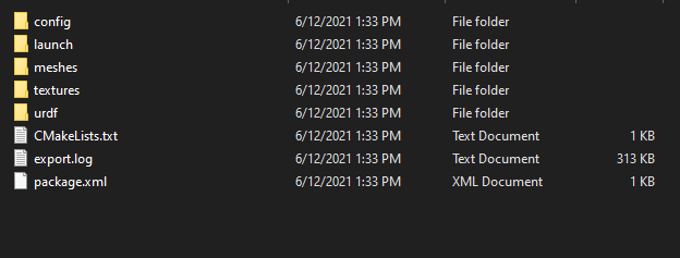
After saving to the folder, the folder should look something like this,
![]()
You can either take the whole folder to an external drive and use in ubuntu, or just navigate to the save location if you are using the same PC in dual boot. Now we are done with the URDF generation, let’s look into how we can use this in ROS with MoveIt!
-
6Setup MoveIt! in Ubuntu
Boot into ubuntu and install ROS if you haven’t, I do recommend using melodic morenia, since kinetic kame is old now, and melodic supports almost everything. Using noetic ninjemys is okay too. This is for moveit 1, which uses ROS1, there is moveit 2, which uses ROS2 (Foxy Fitzroy), but we will not be covering that in this.
So, install ROS, follow this tutorial. And after that, use this guide to install MoveIt! Motion planning framework. The installation process is pretty straightforward, use Ctrl+Alt+T to bring up the terminal and copy paste the commands in the tutorials. You should have a good internet connection at your disposal to do this.
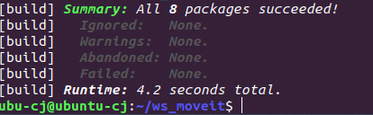
After installing MoveIt and ROS, your home should have ws_moveit (or the name you gave your workspace) folder. Copy the folder that we generated from Solidworks, and paste it in <workspace>/src/. At this point, open a terminal and run these commands
cd ~/ws_moveit
Catkin build
This should take a little bit of time, and should give put something like this (number of packages would depend on the folders inside the src folder, in my case I had 8 other models)
![]()
After that, type
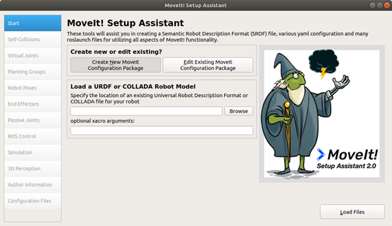
source devel/setup.bashWhich would source the folder you just built. Now, we will use the MoveIt Setup Assistant. This makes making the config files, which would be a complex task, much easier. Use the same terminal and type the following command.
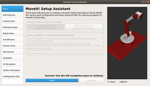
roslaunch moveit_setup_assistant setup_assistant.launchThis will display this window, which we could use to configure the URDF we just made with solidworks
![]()
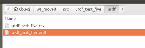
To load the URDF, click the browse button, navigate to
ws_moveit/src/<urdf_folder_name>/urdf .And inside should be a .csv file and a urdf file. Selct the urdf and open
![]()
Then click on load files.
If it gives an error, it probably due to not building and sourcing the files, and if the naming convention is wrong. Check for those if there is an error while loading.
After loading, it should correctly display the model. With the colors (if applicable) like this.
![]()
-
7Configuration of the Joints
we have to go step by step to configure all the joint conditions, end effector information etc.
![]()
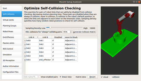
Move onto the self-collisions tab. Click on Generate collision matrix. It should show a table like this,
![]()
This checks for the links that could possibly collide and disable the pairs that would not collide or has the least probability of collision. For an example, base link and the link one collision probability is very low, therefore, we can safely disable the collisions between those two links. Generally, links that are next to each other would not collide, but for an example, end effector and the base are very likely to collide. So the collision detection will be active for those. You can switch to matrix view and get a much more clearer picture.
-
8Generating Virtual Joints
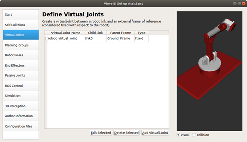
Move onto Virtual Joints. I need to have the base of the robot fixed; therefore, this section lets me create a virtual joint between the base and the external frame (be it Rviz or gazebo) and fix it on to a place.
Click on Add joint, Give the virtual joint name and parent frame name, select the link you want to fix, and set the joint type (I will choose fixed, because I want this to be stationary, but say you are simulating a car, you can use planar (2 DOF) say you are simulating a drone, you can use floating (3 DOF)). After finishing, it should look like this
![]()
-
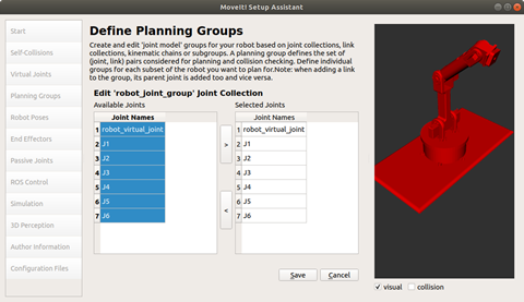
9planning groups
Move on to planning groups. This groups the links that you have together. Or rather, it groups the different kinematic chains in the robot together. In this 6 DOF arm, there’s just one kinematic chain, therefore, will be only one kinematic group. But, for an example, you have a two-handed robot, there will be two groups for the two hands, since they are two separate kinematic chains. For this, give out a name for the kinematic group, and choose a kinematic solver, you can go with the kdl_kinematics_plugin/KDLKinematicsPlugin , which is pretty good most of the time, but of course you can play around with other solvers as well. Click on add joints and will show a window like this
![]()
Select all the joints (or the joints you need in this particular group) and press > which will select the joints and move it into a single group. And click on save to save the group
-
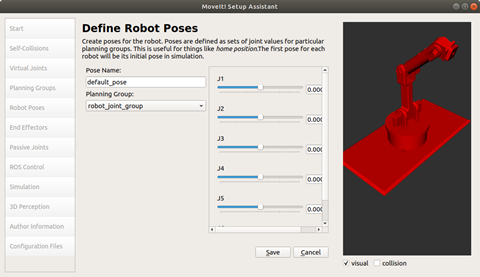
10Defining Robot poses
move onto Robot Poses. We can use this to define default poses for the robot (ex: default 0 position, repair position, calibration position etc.)
![]()
Set the angle needed, and click on save.
Simulate your CAD model of the Robot in ROS
This guides you through how you can simulate a CAD model with ROS


Discussions
Become a Hackaday.io Member
Create an account to leave a comment. Already have an account? Log In.