Close
0%
0%

Electruzzles

Little boxes that snap together and make circuits. An excellent way for kids to explore and understand electronics.
Similar projects worth following
I have a toddler that loves puzzles. I love electronics. The obvious next step is to make electronic puzzles!

I've designed a simple system of construction and use: Magnets hold boxes together, spring-loaded screws make electrical connections, and lids differentiate and expose components to the world. There are 5 base box designs that accomplish most tasks, and the number of lids continues to grow. They are easily 3D printed without support, and everything screws/crimps together except for some lids that might require soldering wires to components (LEDs, capacitors, etc).

The best part is: it's all done in OpenSCAD, and new parts can very easily be added to the list.

So I had a project I was working on, and I saw that it fit one of the Hackaday Prize challenge rounds, the 3rd in particular.: Reimagine Supportive Tech. This includes educational projects. I have a young daughter (2.5 years old) and I wanted to introduce her to electronics gradually, and in a way that helps her understand electricity and electronics naturally and intuitively.

So how do we go about teaching the extremely young about electronics? My daughter just so happens to enjoy blocks and puzzles, and I quickly decided this was the best route to accomplish my goals. If I could build a lego-like system that works similar to a puzzle, I could give her some plastic blocks, show her how they fit together, and let her experiment. Of course the focus should be on the flow of electricity and not struggling to fit things together, nor should they be possible to fit together improperly since children her age often can't pay attention to too many details at once.  My hope is that my idea will make learning electronics possible for the very youngest of future engineers (should they decide to go that route). At the very least, it should give my daughter a better understanding of the world she lives in.

I'm releasing my project into the open domain. I have written everything in my OpenSCAD file from scratch using measurements I made myself. My goal is education. I feel that an open domain dedication is more likely to accomplish that goal than any other license. Take my work and do with it what you will. I hope you find success.

electruzzles.scad

The OpenSCAD file to build all of the parts needed to make Electruzzles. Everything you need to know is in the .scad file. I'm calling this version 0.2.1 due to the number of revisions I've done to it, not the number of times it has been released. I'll try to clean it up a bit in the future.

scad - 38.11 kB - 08/14/2021 at 07:02

Download

  • 3 × M3 12mm pan head screws (1 per output)
  • 1 × Mini neodymium magnets (2 per input/output) 3x6mm I get mine at Daiso 100yen store for now. Might need a cheaper source.
  • 3 × M3 18mm pan head screws (1 per input)
  • 3 × M3 5mm compression springs (1 per 18mm screw) 0.3x4x5mm
  • 3 × M3 nuts (1 per 12/18mm screw)

View all 10 components

  • A quick demo

    John Daniels08/23/2021 at 13:48 0 comments

    Here's a quick demo of the game in action. The video didn't auto rotate, so I'll fix that soon. Please pardon the portrait mode.

  • Hardware to hold together your hardware

    John Daniels08/23/2021 at 07:11 0 comments

    When I first started prototyping these boxes, I used what I had on hand to put the first one together. This includes screws of non-ideal lengths and shapes. Ideally I'd have some smooth shafted, non-tapered (as in counter sunk) flat headed, tiny bolts, maybe even hex bolts. However, I didn't start with that on the prototype. I started with pan headed M3 screws. I then bought more because I wanted to limit the number of variables I was changing. In the past I've changed a lot of things at once and the results were not always positive. In an effort to grow as a designer, I've run into new problems. Oh well, that's the learning process, and that's why I love making things.

    So I have been using pan head screws, and the connection is somewhat shaky. I believe it may be because of poor connections as the rounded heads of the screws only touch each other in small little points. Maybe it's not as bad as I expect due to the driver slots. However the connection is shaky, and it's something I'd prefer to fix.

    So my thought was to get some flat head screws. I also noticed that I could probably safely change the length of the screws a bit to save some space inside the boxes. Why didn't I stick to changing one variable at a time? I don't know. So now I may have a bunch of screws to use on other projects. Time to buy more screws? Maybe. Except, the flat head screws actually seem to be worse than the pan head screws. Is that because I bought screws that were too short for a good connection? Or is it because the tapered head causes a wider gap? Perhaps the the slight tilt to the head due to the internal wiring is the problem. That would reduce my flat contact surface to a tiny spot on the rim of the head. The result is the same anyway: a worse connection than pan head screws. So I'm going to have to continue to experiment with screw sizes and shapes.

    For now I'm going to stick with the pan head screws I bought first. Most of my boxes use them, and they work well enough until I find something perfect.

    Flat and tapered on the left. Pan head on the right. The pan head clearly sticks out more and that seems to reduce the amount of travel the screw has to undergo when depressed. That travel distance is dependant on the receiving end as well, so it may not seem obvious, but it's happening. I do prefer the tapered head on the test point connection that we see on the lid. It gives multimeter and oscilloscope clips something more to hold on to.


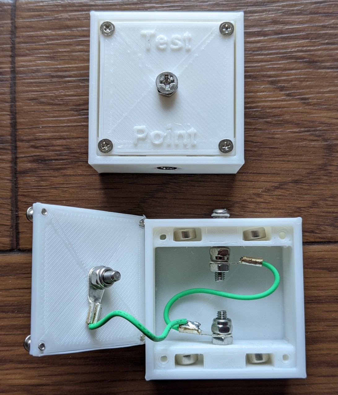
    Reviewing this picture I posted before, we can see the internal connections. I'm experimenting with different orders of different nuts to save space and reduce the likelihood of something coming loose. The nylon lock nuts do their job, but they take space. Especially next to the spring loaded portion (hidden by the pladtic case and between the magnets) the nut should not move or the ability to make a connection could be affected to the point of failure. A bit of cyanoacrylate could lock the non-lock nut, but could also inadvertently cause insulation on a necessarily conducting part. Bigger boxes would make everything easier, but bulkier and less toy-like. Not really something I want to do. Failing educational toy, this could be a great coffee table puzzle for guests to fiddle with. If it's huge, you won't want to keep it on your table, I bet. I wouldn't. You might notice some solder on the lower wire. I forgot to crimp that one and couldn't be bothered to redo the whole thing. Oops.

  • Lids: The Window to the World

    John Daniels08/23/2021 at 03:34 0 comments

    By having some relatively static boxes to build on, the lid became the best means to differentiate the puzzle pieces. I found that this idea offered just enough flexibility to accommodate my goals. I can provide illustrations on the lids as well as outside access to the internals of the boxes. It's a very simple concept that has worked out wonderfully.

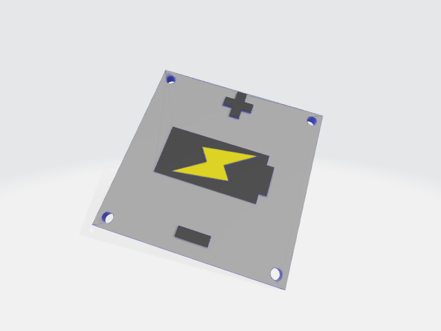
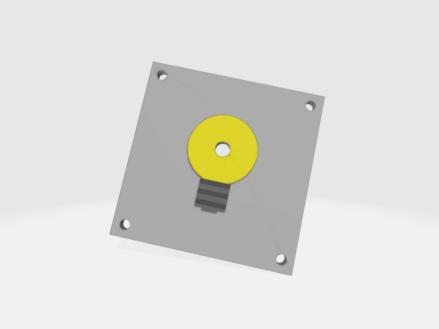
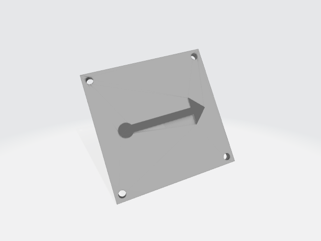
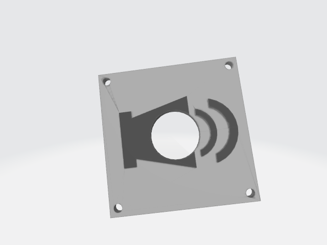
    My ideal lid design would be completely pictographic so that people who are too young to read can still figure out how to use the pieces, would allow the internal components to contact the outside world when necessary, and would properly prevent access to parts that might break when coming into contact with little hands (true forces of nature which like to shove things into mouths). I have attempted to adhere to these ideas in most of my lids, but a few of them have been given temporary designs to help me get things out the door while I ponder the best way to design a lid that sticks to these rules. My lid for potentiometers is the first clear exception to my goals. It's all text and is only useful for people who already have a hint as to what is going on. It's going to have to change in the future, but I haven't yet drawn all my lines between schematic symbols and intuitive pictograms. I currently consider that a cosmetic issue since I'm still working on functional design, but at some point in the future, I plan on standardizing the rules of lid design. Until that happens, here are some lids (both good and bad) out of the 22 that I have designed so far:

    Battery lid

    LED lid

    Passthrough lid (a straight trace)

    Piezo buzzer lid

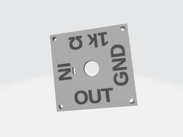
    1k ohm potentiometer lid


    I will continue to add news lids as I go. My soft end goal is currently to build a simple AM radio. I'll design at least enough lids to accomplish that or some similar circuit.

    (I colorized these STLs in MS 3D paint. It was the easiest way to make the details visible. They normally look like standard OpenSCAD STL files.)

    Next I'll discuss hardware (nuts and bolts) and that will catch us up to where I am now.

  • Box Design

    John Daniels08/16/2021 at 05:56 1 comment

    Today I'd like to take a moment to discuss the design of the boxes in my project. Like any good building block, there needs to be a certain level of uniformity so that creativity has space to grow. Sometimes we are more inspired to be creative when certain limits are imposed on our actions. If you can do anything at all, what would you do? That's a hard thing to decide if your decision matters. If you have 3 hours on a Saturday afternoon, what would you do? That's a bit easier.

    Similarly, a box that can do too many things leaves us wondering what's the point in doing anything? A box that has limits challenges you to push those limits. So I decided to start off with a simple cube with 2, 3, or 4 inputs/outputs. This keeps things simple and makes us think about how to get more out of our boxes than we might otherwise believe is possible.

    I chose the size of the boxes (40x40x17mm) based on estimates of how much space I would need inside the box for screws to jut out into the middle of it, for small components to fit inside of it, and for ease of holding and placing the boxes exactly where you want them regardless of the state of your finer motor skills. 40x40mm seemed just right. The 17mm came from estimating 15mm of space as a minimum, and adding 2mm for the height of the lid. The lid was originally 1mm until a test print convinced me to double that thickness to 2mm. I still use that lid (it's the one with the black marker on the arrow), but it's definitely flimsier than the other lids. Luckily it's not supporting any components. It just sits there. Along with the details I've already discussed in previous logs, that fills in my considerations for the boxes. They're simple, sturdy, don't need print support, and just a few different designs make up most of the boxes you'll ever need to print.

    However, I did run into a problem with one particular lid/box combo. The potentiometer box was too small at 17mm tall. The screws would touch the potentiometer no matter how I tried to turn, shift, or hack my way around the size constraint. So I went a route I was hoping to avoid: I made a taller box. Why didn't I want to make a taller box? Well I didn't want to complicate the box system. I only designed 5 boxes that will fill 99% of my use cases. Having random unicorn boxes is annoying and upsets the uniformity of the puzzle. So I tried my best to simply make it a tiny bit taller. Just enough to give me that extra space without turning the whole thing into a cosmopolitan skyline. In retrospect, I like the slight pronounced look of the potentiometer box. It seems to draw attention to it, which is good since it's the only piece that requires user interaction after being placed. The best part is, the only thing that has changed is the height of the box. The lid and everything else are all the same.

    Since I was mucking about with my boxes and the sizes of them, I decided I'd go ahead and throw in one other possible box variation I was thinking about: the double wide box. This is a box that is 80x40x17mm. It's exactly as if you had placed two boxes side by side. In fact since you can place two boxes side by side, there are probably not many things you can do with it that you can't do with two boxes, but there is one thing that I was hoping to achieve: 6 IO in one box. While I haven't used or even printed it out yet, I can see it getting used in the future. I decided against making this box taller as well, because the number of changes would quickly cascade out of control, and losing the 4mm of walls that would normally be present in between two boxes provides us with more space anyway.

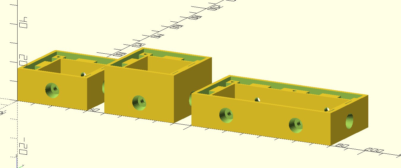
    Here's a screen capture of the 3 different styles of boxes in OpenSCAD. You can see the taller box printed in the photo gallery. I haven't printed the double wide yet. I just haven't needed one. I'll probably end up using one for a rechargeable battery pack.


    I was planning on writing about the lids as well, but this is already long enough. I'll discuss the lids in the...

    Read more »

  • A Quick Jump to Version 2

    John Daniels08/15/2021 at 09:58 0 comments

    So I went back to the dollar store for an unrelated purchase after printing my 3rd version of the center magnet box. I popped over to the stationary aisle just to see if anything had changed in my favor, and indeed it had. They had a nice fat stack of mini magnets. These are 3mmx6mm and quite strong for their size at 280 milliteslas (compared to 240 for the larger ones, umm ok). A dollar buys 8 of them, so enough to make 2 boxes with 2 IO each. Half a dollar for a box is approaching (if not slightly past) my ideal cost, but since everything else is super cheap, I haven't felt the need to source cheaper alternatives online.

    Using these magnets was my original idea, so I decided to quickly change the design to incorporate these magnets instead of the slightly larger ones. Since I tried to make things as modular as possible in my .scad file, it worked out very quickly. I wanted more pulling power, so I put 2 magnets per side, and I changed the design to use a centrally located electrical connection to simplify everything and equally distribute forces. The main issue I was running into with the offset screw connectors was that they tended to get bunched up in the corners when building L shaped pieces (see the previous image of the v1 box). Centering the connector made each side equally in and out of the way of the other sides. I didn't want to make these boxes very big (relatively speaking), so things are a little cramped by design. Of course I also didn't want to make everything too small, or children would have trouble manipulating the pieces.

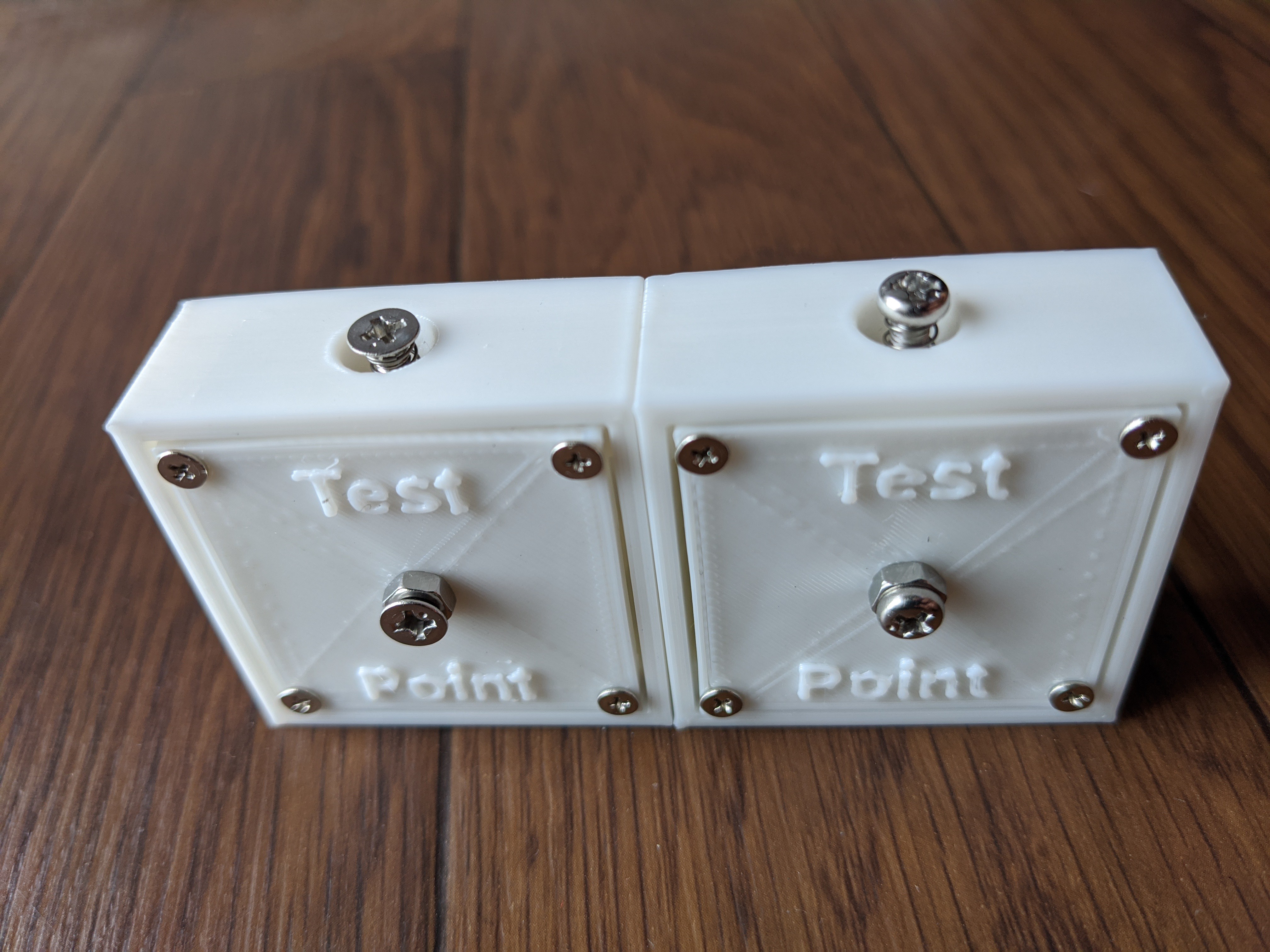
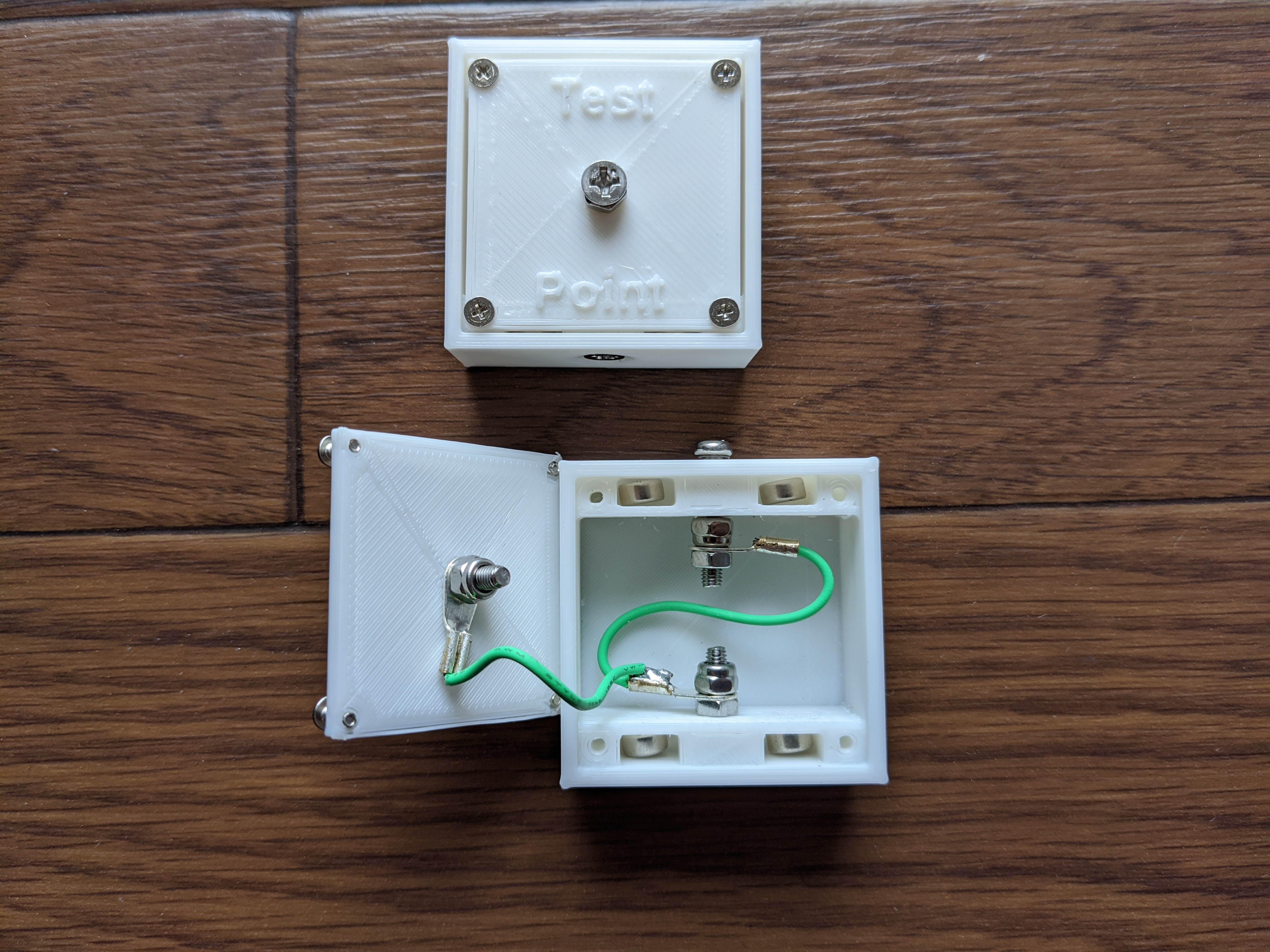
    Here is an example of the inside and outside of a simple v2 pass-through box. The lid on this box is a "Test Point" lid, so it's purpose is to allow us to tap into the circuit at any point and test the integrity/characteristics of the circuit easily with a multimeter or oscilloscope.  The keen observer will notice a few differences between the hardware on the boxes as well as the hardware on the different connectors within the same box. I'll address these points later. The S shape of the wire between the 2 sides seems to be the ideal shape for the wire to allow the spring loaded screw to depress without becoming jammed by the threads on the screw. Clearly a smooth shafted part would work better here, but we're dealing with DIY prototypes. It'll be ok.

    More to come soon. The next chapter will be about all about my design decisions of the various boxes and lids.

  • My initial idea and attempt.

    John Daniels08/14/2021 at 06:45 0 comments

    My idea is to make a puzzle like game that involves putting different boxes down in a circuit. I'll have some active boxes (sensors, LEDs, etc), but most will be passive boxes (like traces on a PCB). My first thought was to use magnets to hold things together, and (at least for the time being) screws to make the electrical connections. One screw would be recessed and the other spring loaded.

    I thought I had enough to go on and started designing some boxes in OpenSCAD. At the same time I started looking for the mini neodymium magnets I've used before from the dollar store. I couldn't find the mini size that I wanted, but I found a smallish medium size. I figured, more magnet, more pull. So I first started a design with a central magnet and a left sided input for each face of the box that would be a connection interface. I used some screws and nuts that I have from old projects on these first few boxes to figure out tolerances and dimensions, as well as determine the feasibility of the entire project.

    My initial attempt was a partial success. I got a connection when the hardware was installed, but the magnet couldn't quite pull strong enough to make the boxes fit together flush. I figured this meant the connection wouldn't be great, so something needed to be done. Time to search for different magnets...

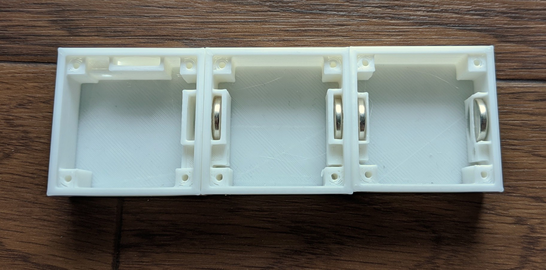
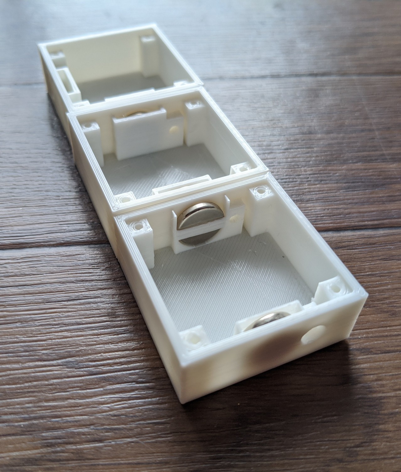
    Here are a couple of photos of my first prototypes without the screws installed. Notice the extremely thin walls on the magnet holder on one box. That was the first I printed. Each of these three are slightly different as I was still dialing things in.  This style of box was abandoned after these 3 prints.

    More of the story to come soon. Once I catch up to where I am now on the project, I'll switch over to more update-like posts.

View all 6 project logs

Enjoy this project?

Share

Discussions

John Daniels wrote 12/21/2021 at 06:57 point

Yay! I finally got comments. Too bad they're spam. wah wah waoooooh.

  Are you sure? yes | no

Similar Projects

Does this project spark your interest?

Become a member to follow this project and never miss any updates