-
Mill Toolsetter
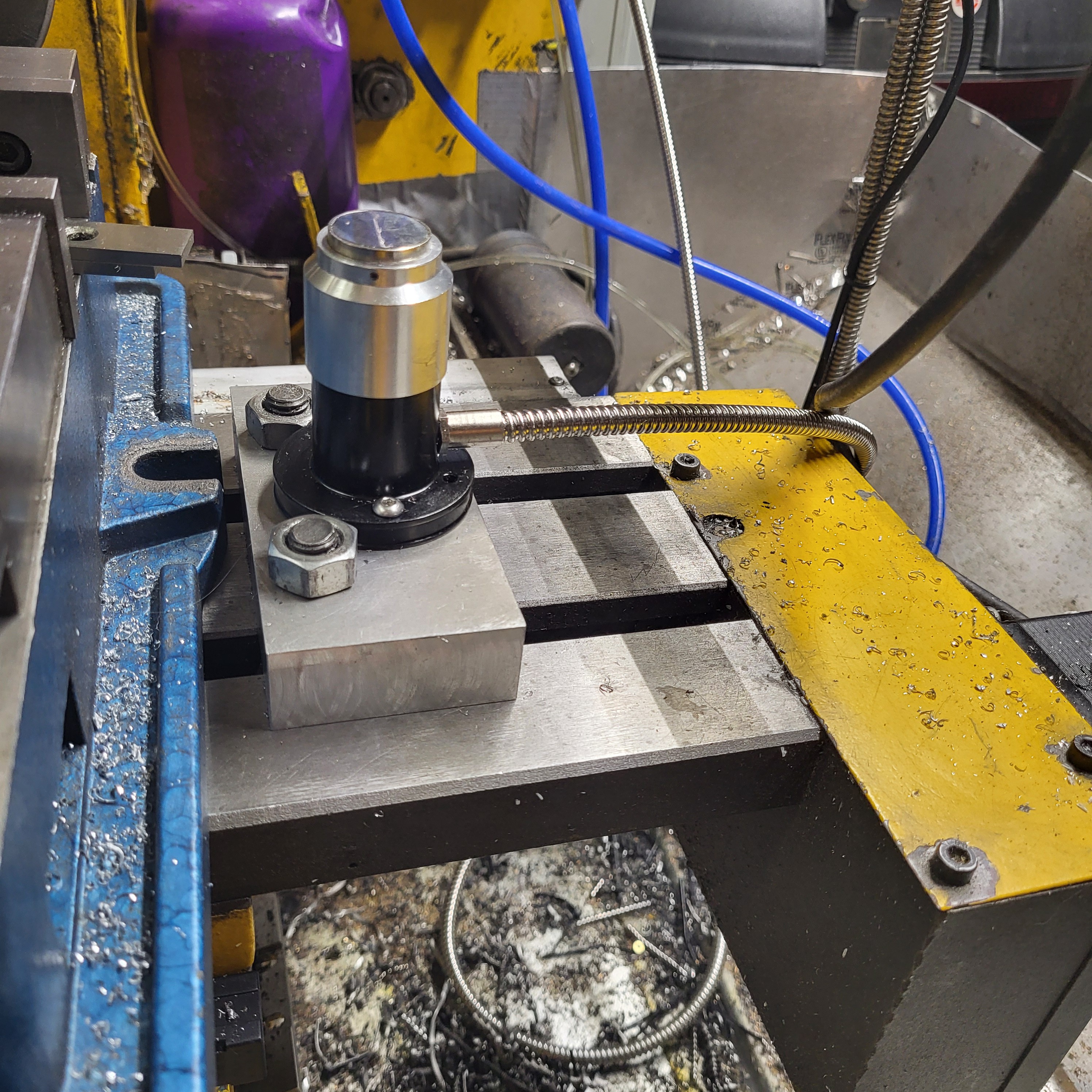
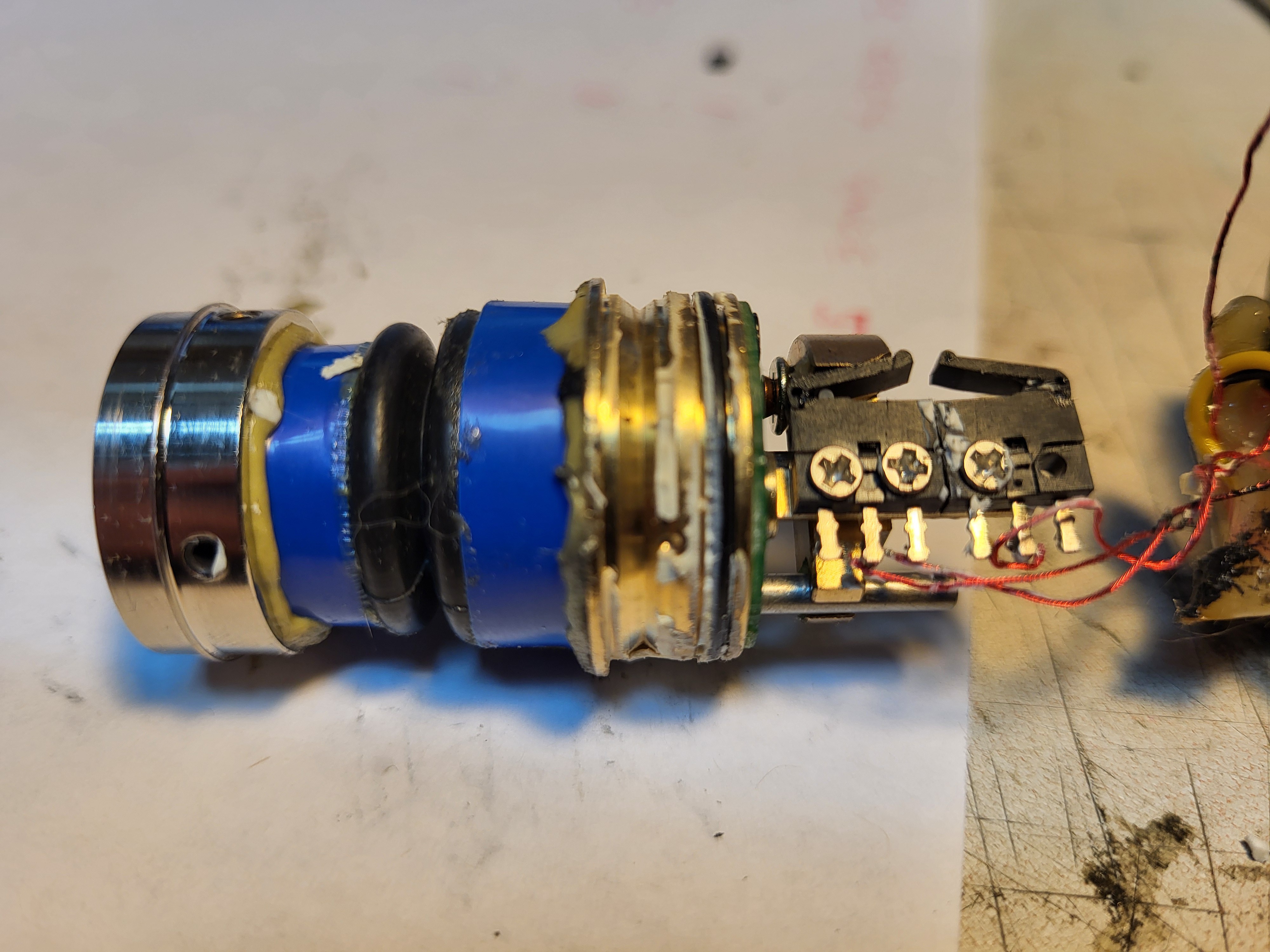
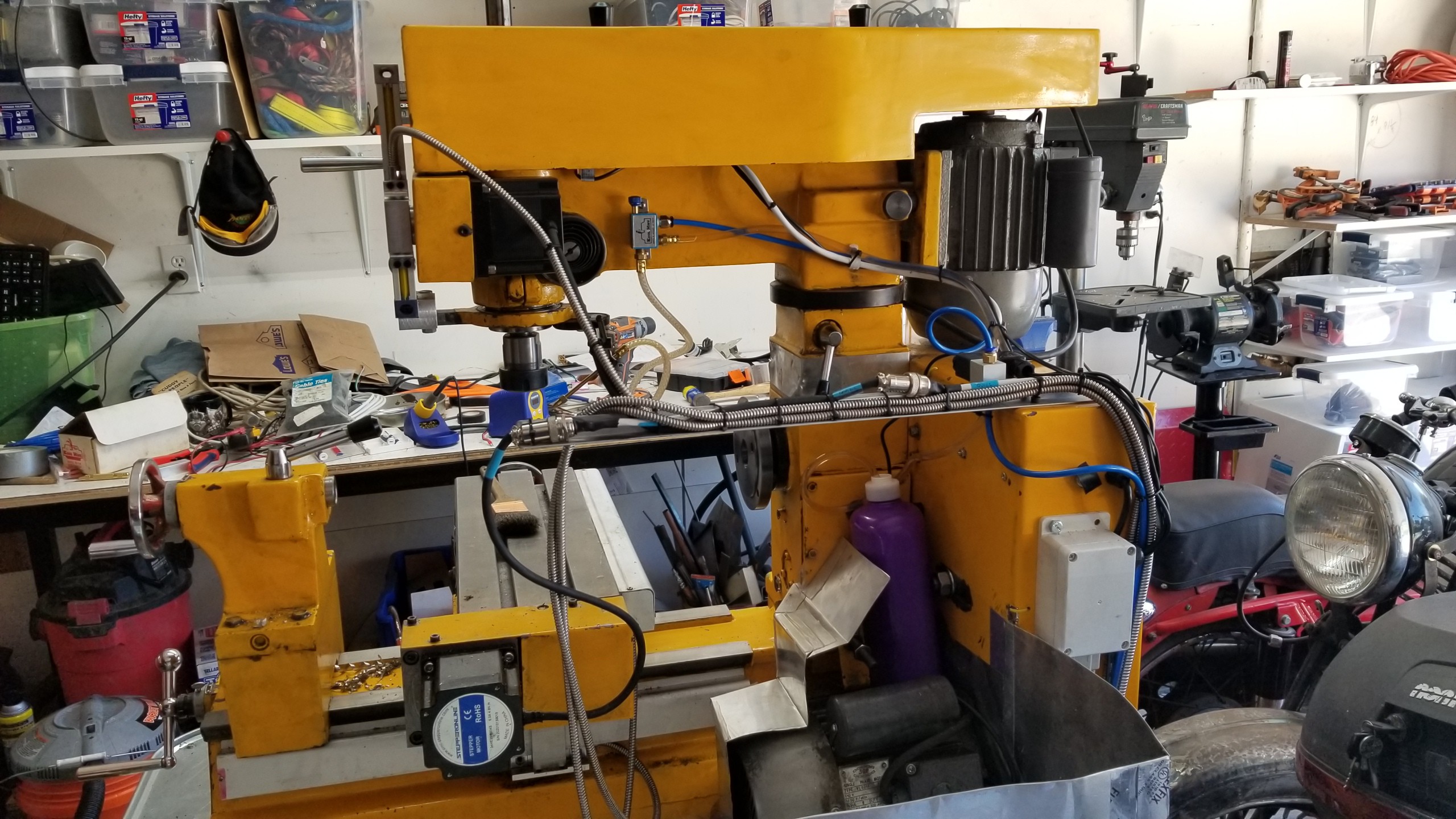
03/07/2024 at 05:23 • 0 commentsI purchased a lower cost tool setter, figuring if it is bad I can at least experiment with it and make something better. The mechanicals are not terrible but the electrics are crap. I think that some earlier iteration of these had a piezo electric tip, but this one just has two tiny plastic microswitches, one of which came with a broken wire. In service it does seem to give about 0.002" (5 micron) repeatability so it will do for now. I don't expect it to last.
I found some code on the forums and simplified and adapted it. The original code has a touch-off step then updates the tool offset each time without storing to the tool table. It also has you hard code in your tool setter and tool change positions. As neither of these are fixed forever positions on the Shoptask, I reworked it to use G59.3 origin for the tool setter and G28 for the tool change. I also added a retry loop for when I have to juggle different holders to make the tool reach, and have it updating the tool table with the spindle-nose to tip length. That last bit isn't actually necessary but at least I can dream about an array of fixed tool holders. This way as part of my setup I can quickly touch off the tool setter location in G59.3 (if it has been moved) and save my tool change location with G28.1 in a place where I can get around the work and not collide with anything.
Code is here. EDIT: check the next code checkin. I had to remove the retry logic as it crashed the gcode emulator in LinuxCNC when I actually used it in anger.
![]()
![]()
-
Axis disable buttons, lathe encoder upgrade and homing
02/29/2024 at 02:05 • 0 commentsThese updates happened over a period and I have not been diligently updating this log.
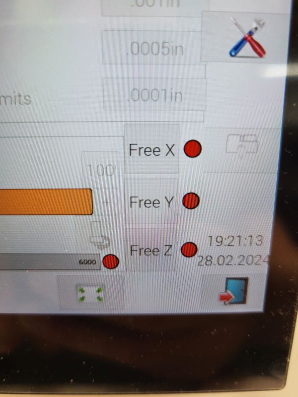
I found that during finishing passes I would get a small amount of hunting ripple in the finish due to the acme screw backlash. To avoid this on a manual machine you would lock the axes that are not in use, but doing that on a CNC machine quickly leads problems as the motor fights with the axis lock. The solution was to add some HAL logic and buttons in the UI which disable those motors, and to use M0 pauses in the gcode to add the operator actions to enable and disable this mode.
![]()
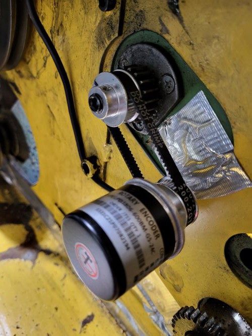
The next update was to finally install the rotary encoder on the lathe spindle, allowing for faster threading. When using the pulse encoder, which is good for rpm reading, I had to run the lathe very slow or it would risk missing pulses as the pulse was narrower than the servo thread wavelength, as the mesa card is polled at servo thread rate, and I was forwarding the sensor state up to the linuxcnc encoder object. This encoder is driven off the old threading feed gear which runs at one-half spindle speed when the lever is in the II setting. The pulley is threaded to replace the nut with a set screw in the end to lock it in place. The main code change is to move from the linuxcnc encoder with interpolated angle to the Mesa card encoder which returns the current angle at each poll.
![]()
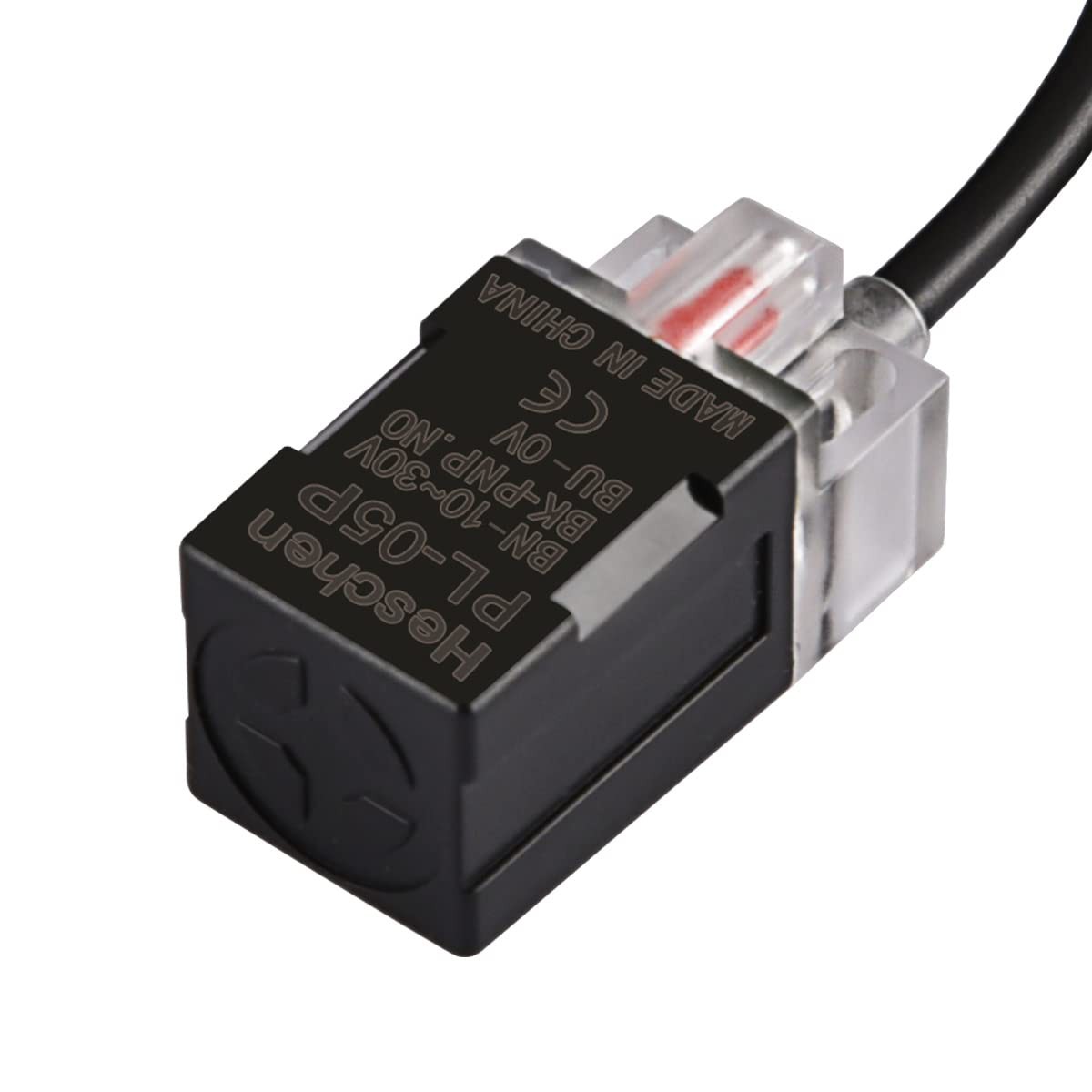
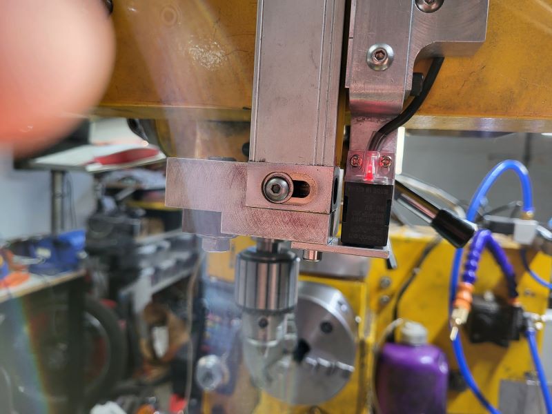
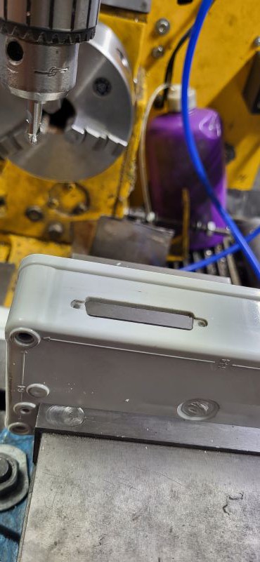
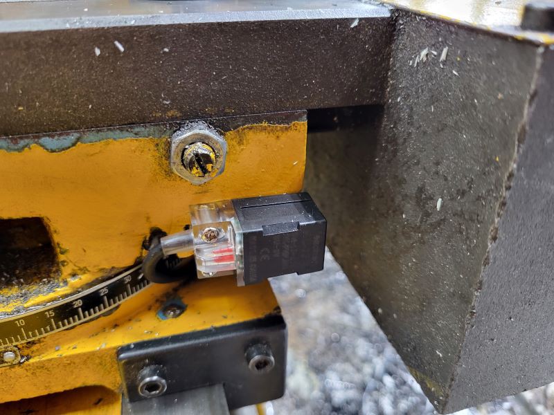
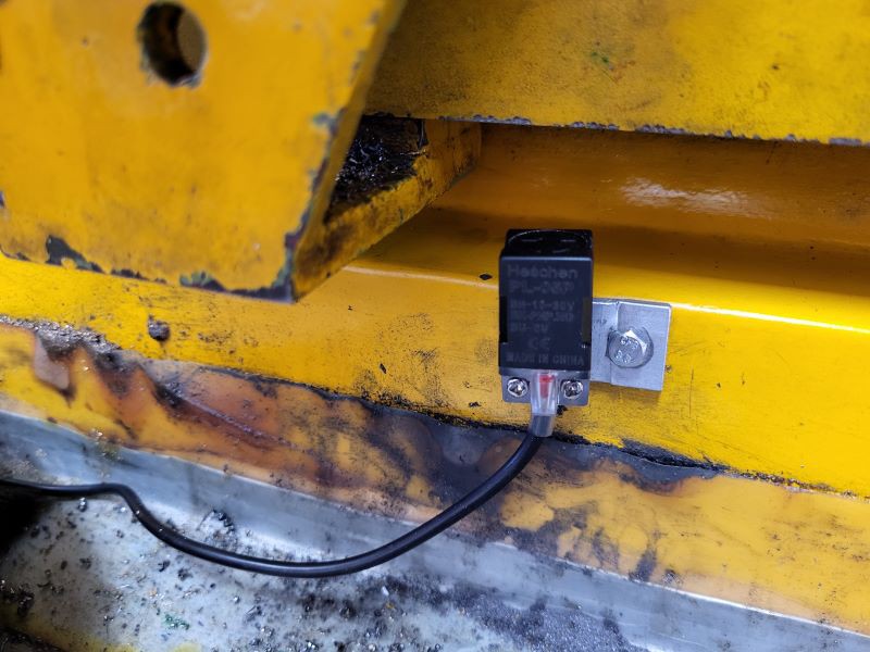
The most recent addition is homing switches using proximity sensors. Rather than using the common barrel type I thought the square type would be easier to mount, and they were. They appear to give better than 0.001 repeatability. This gets around the annoyance of having to go to home before fiddling with gcode files on the console, which is still causing occasional crashes of LinuxCNC.
I used Heschen PL-05P sensors.
![]()
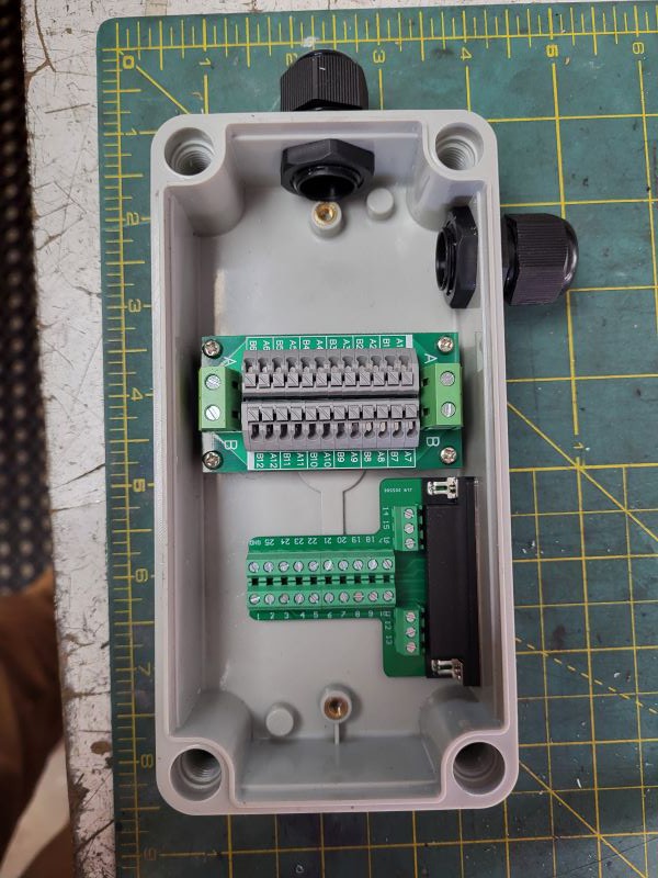
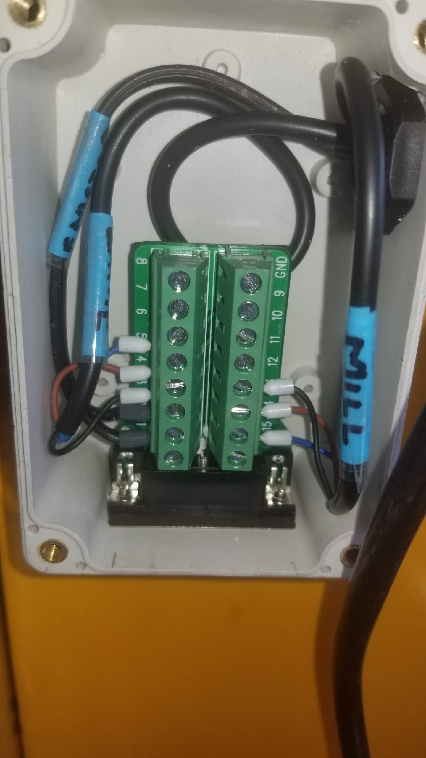
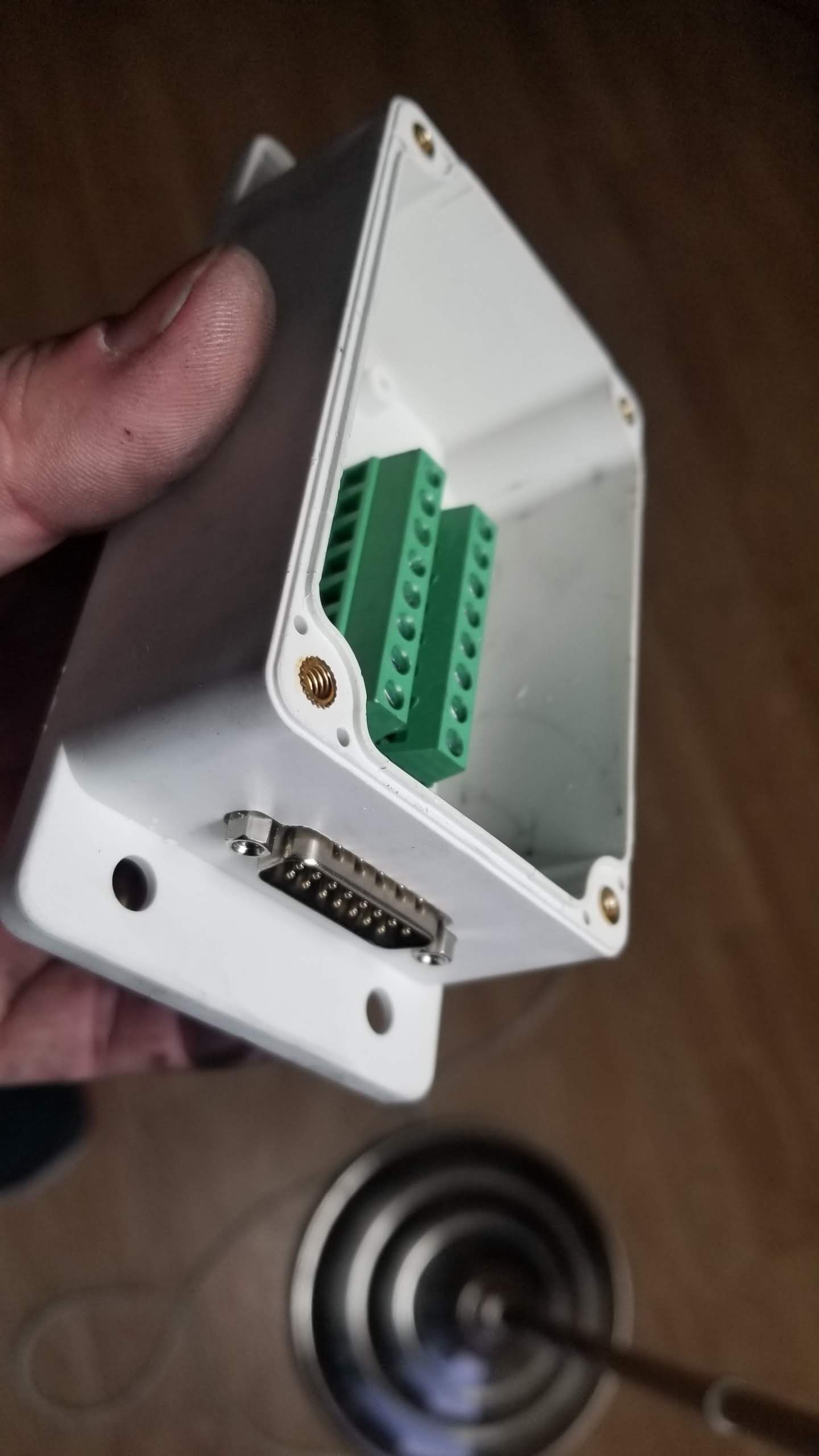
I had to replace my DB15 uplink with a DB25 as I needed more pins. I would not use this type of DB25 breakout again as the rows of screw connectors meet on an inside corner and it is very difficult to get wires with ferrules on them into both sides of those corners. The bigger breakout box now includes a distributor for field power as there are now 4 things using field power ( these + EMSTOP) and one using field ground (mist coolant). Future toolsetting sensors will use this too. Several unused INPUT and OUTPUT pins are prewired in the control cabinet to free DB25 pins for future use.
![]()
![]()
![]()
![]()
![]()
-
XHC-HB04 Pendant Configuraton
07/06/2022 at 06:19 • 0 comments![]()
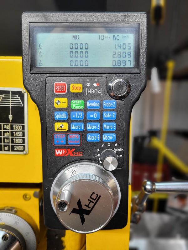
I picked up an open-box XHC-HB04 pendant as I saw that others have done the hard work of writing the LinuxCNC drivers for it. It took a while to figure out how to configure it. There are different versions of the instructions online. Finally I realized that the newer instructions are really simple, and the complicated stuff has been packed into a TCL file, and the instructions are in the TCL file itself
https://github.com/LinuxCNC/linuxcnc/blob/master/lib/hallib/xhc-hb04.tcl
This gets the pendant working for basic functions, though I made some enhancements in my custom_postgui.hal.
The first handles switching from inch to metric. This uses Kurt Jacobson's halunits.py component to return the G20/G21 state (inch/mm) which is used to toggle a mux2. The mux2 either outputs the raw feedback value or the value scaled by 25.4 i.e. metric value into the pendant display.
In lathe mode there is an additional scale component to double the X value and feed it into the Y display to generate the diameter value like on the gmoccapy DRO
I programmed the zero and half buttons, and I have the smallest MPG scales as 0.0002" i.e. approx 5 microns which is the glass scale resolution.
I did have to rejigger my emstop and spindle start/stop logic quite a bit. I need to map that out and make sure I understand it. It seems to work as intended.
Homing buttons home, and the A axis home does a home all.
I have the go-to-zero set to go to machine zero. I set machine zero as my tool change position before each setup, so that is useful. I may change this if and when I install home switches.
Macro-1 sets the Z to 0.025 as that is the feeler gauge I use for tool height setting.
Lathe code update: https://github.com/arielnh56/shoptask1720/commit/85b2034e365fe63b4d79b3ed27d1f3dde79f98ee
Mill code update: https://github.com/arielnh56/shoptask1720/commit/3d1de84de7ae257f491b138af5d7f085719d6b7f
Having the MPG available is really handy.
-
Milling a Gear
12/07/2021 at 15:24 • 0 commentsThis was the second attempt. The first one was gnarly due to too high DoC and loose gibs, table off square and a loose X drive train.
-
Milling Videos
11/20/2021 at 21:42 • 0 commentsSome peck drilling in 1080, and keyway cutting in W1 tool steel. This is all handwritten g-code. I find for these kind of operations it's easier to tune this to the machine than working through the Fusion360 CAM.
The keyway cutting video quality is crappy due to the free editing software I used. Learning....
-
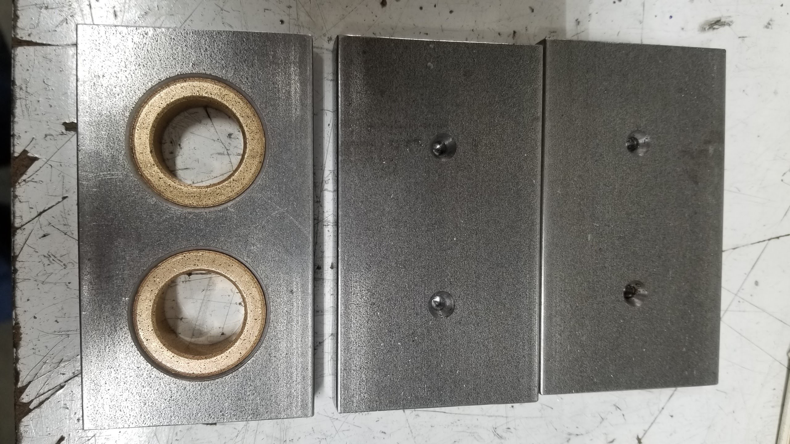
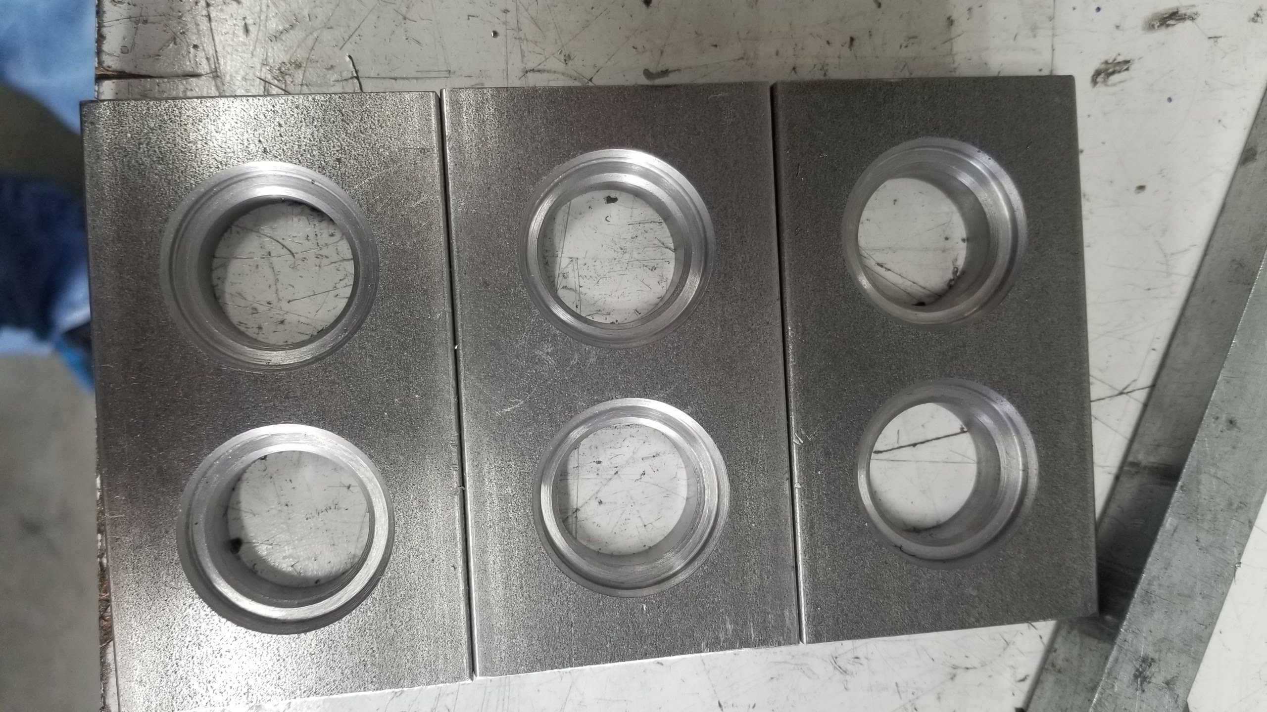
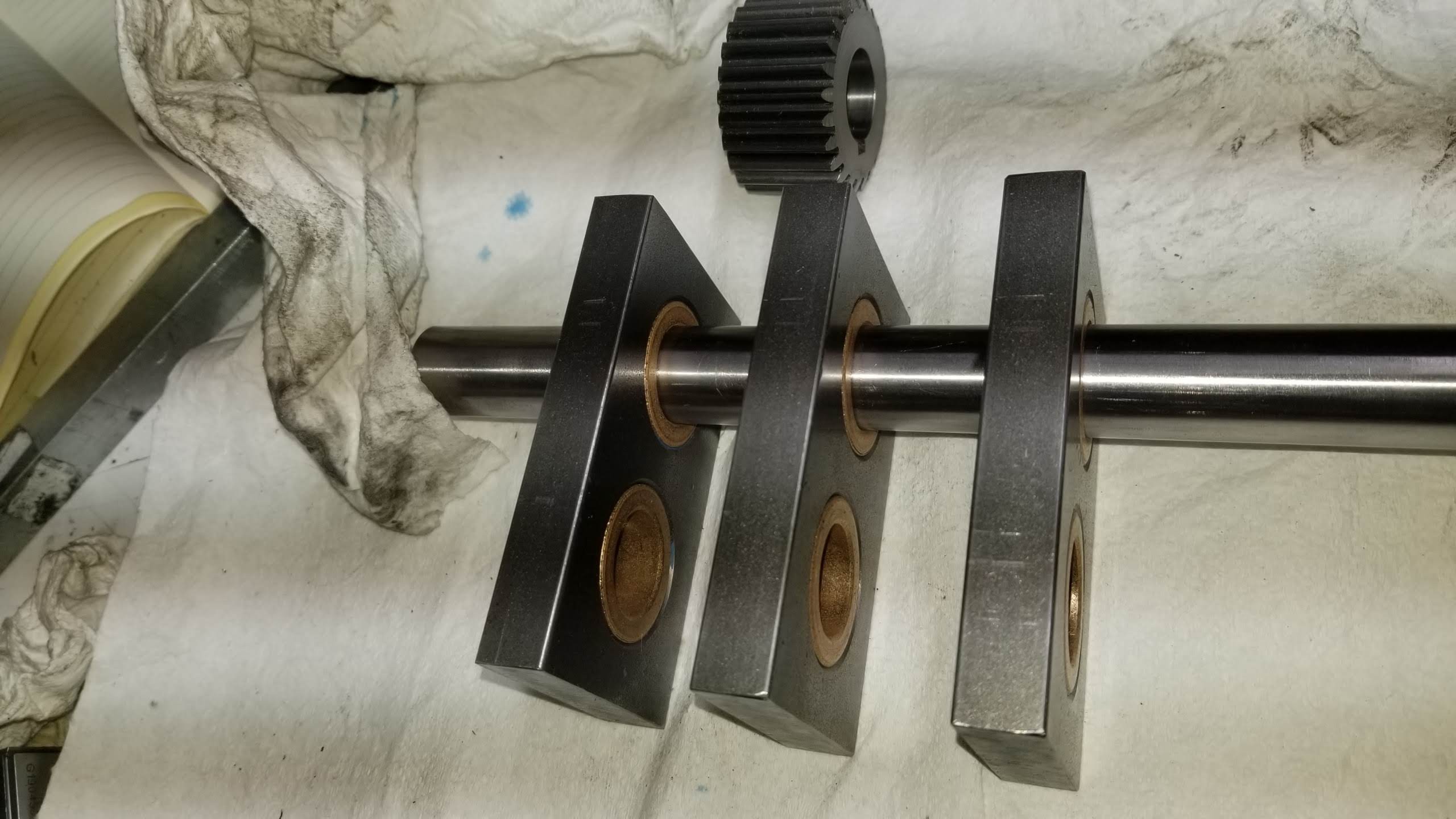
Bearing Boring
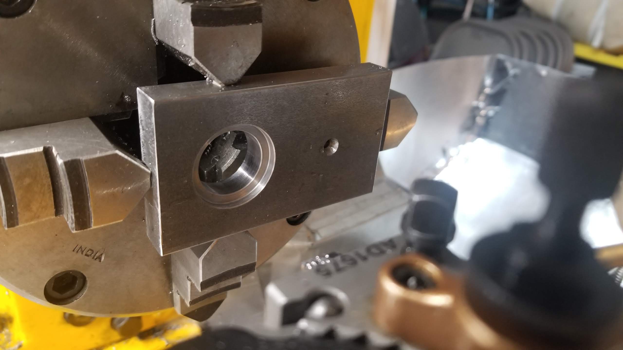
11/09/2021 at 08:16 • 0 commentsThis is my first real use of the CNC to make something. This is a project I am doing to make a penny squashing machine. Because the forces involved are huge, the frames are in 1/2" 1018. The plates were all squared identical on the mill and the center drills for the holes also marked out on the mill. I used these to indicate in the part in the 4 jaw chuck using a 2MT dead center on 3MT-2MT extension in the 3MT-3MT extension mounted in the tail stock. Parallels behind the part to make it flat, removed after indicating. The dial indicator resting on the extension at the nearest ground location.
Then I drilled out most of the material for the bearing holes. I bored it bit by bit the first time and hand crafted the g-code as I went, wrapping the already-run code in
O100 WHILE [0]
O100 ENDWHILE
until I got the feeds and speeds and chamfers right.
Then it was pretty quick to iterate through the other five, though I always stopped to check the bore diameter before running the final pass.
The bearing bores are for 3/4" drill rod.
Things learned:
- Side milling the ends of the plates with the 3/4" 4 flute mill came out very un-square across the thickness. Tramming? Flex? I was able to end mill them square and there is enough clearance at the ends that having them a bit shorter (but all the same) is ok.
- The 6" 4-jaw is a little too big and the 8" faceplate it is mounted to is much too big.
- I really want to see if I can move the table linear scale to the other side - away from the chuck. I think it make be possible by rotating the the thing it spins on. I can't just bolt it on the other side as the gib is there.
- The table had gotten out of square, so I should re-check it every time I square the vise.
- More splash control/chip guards still needed. And a holey rubber mat. I'm getting yelled at for tracking chips into the house.
![]()
![]()
![]()
![]()
The gear in the picture is cut from McMaster gear stock.
-
Spindle Encoders, PID and Threading
10/13/2021 at 00:48 • 0 commentsI had an interesting time getting the spindle speed feedback to work with the feed-per-revolution and G76 threading.
The position interpolation in the HAL encoder component for the single pulse encoder is not available in the Mesa encoder component.
So the encoder itself is wired into the A channel on the Mesa encoder - not the index. I intend to move it to the index when I get the quadrature encoder installed. The input A signal on the mesa encoder is fed to a HAL encoder on the A and Z channels. I can then take position interpolation for threading from there. However as the Mesa is only read at servo-thread speed, this will probably not work at higher rpms, unless I install a wider magnet on the pulley to make the index pulse wider. So for now I am threading at the minimum speed which is 165RPM. The pulley table says 120, but it lies.
I made myself a little function to simplify cutting UN threads - it takes the thread length and TPI and figures out the rest.
Initially the first threads in each pass were too wide - I could see the X handwheel still turning for the first 5 revs or so. Giving it a "run up" was a workaround but clearly my PID was not taking up the backlash quickly enough - X currently has 0.011 backlash possibly due to the earlier toll crash loosening the acme nut.
So I spent a couple of evenings playing with that.
This youtube playlist was helpful https://www.youtube.com/playlist?list=PLPgfyZozUfKrY_qa1ZNW0ldwaJJl6c5Qm
I eventually found the following:
- More P is good. Until it isn't.
- Too much accel is a bad thing
- I and D suck. Avoid.
- FF1 is magical, but a little goes a long way.
Watch the github repo for the numbers I settle on.
![]()
-
Wire Management and Coolant
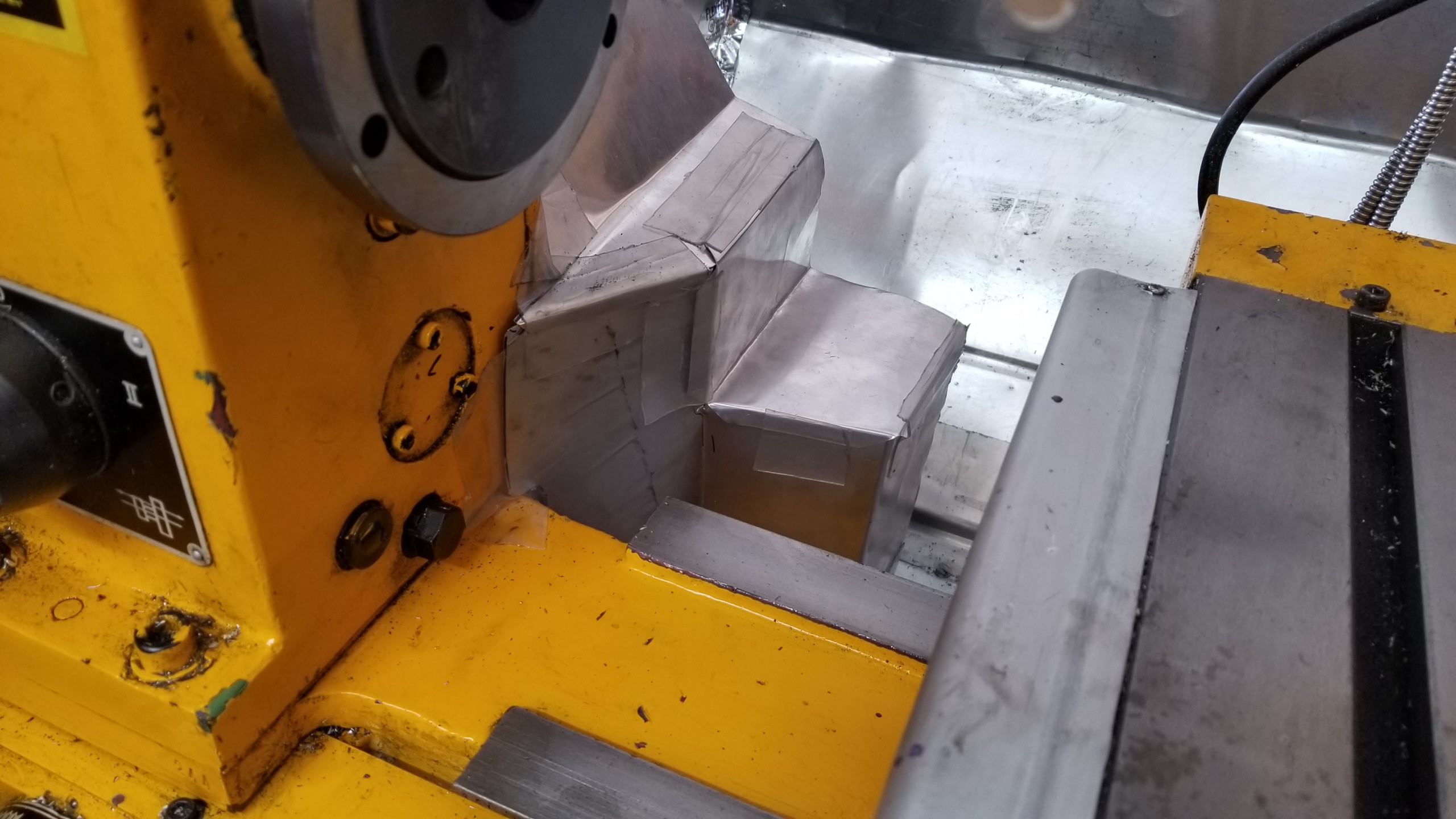
10/02/2021 at 21:22 • 0 commentsSome pictures of the wire management and mist coolant installation. The chip tray has been trimmed with Flex Tape to prevent drips.
![]()
![]()
![]()
![]()
-
Wiring Updates
09/29/2021 at 05:18 • 0 commentsThe first cuts showed that I really, really needed an integrated STOP. The spindle switches are now awkward to reach behind the monitor, and don't stop the steppers, and the stop in LinuxCNC doesn't stop the spindle. Not safe.
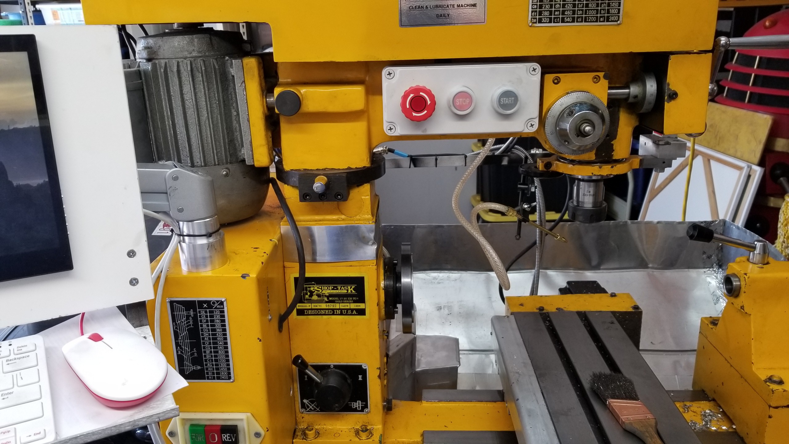
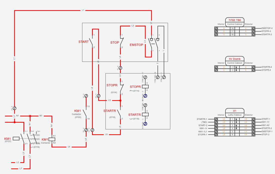
So I have added a contactor, a three button start/stop/estop box and a couple of relays wired thus:
The relays are in the control cabinet, and the contactor is in the Shoptask panel along with a terminal block to wire it together. The operating theory is based on the use of the manual buttons which are wired with 110V along with the contactor coil and the auxiliary contacts on the contactor. In this mode a momentary push of the START button energizes the contactor which then latches on. A momentary push of the STOP button breaks the circuit and the contactor unlatches. Likewise with Estop. The two relays mimic the STOP and STOP buttons, the STOPR being in series and the STARTR in parallel. A second switch in the estop goes back to the mesa card and runs at 24V field power. HAL is set to set to energize the relays momentarily when the spindle enables and disables, and will also energize the STOPR relay when the machine is disabled. In this way the estop in LinuxCNC disables the spindle, and the manual estop triggers the LinuxCNC estop. When the machine is enabled but the spindle is disabled, the manual buttons can still start/stop the spindle (without LinuxCNC knowing), likewise when the controller is plugged in but powered down (or LinuxCNC not running). For times when the controller is unplugged I have a DIN socket mounted on the Shoptask cabinet to plug the loose cable in with two pins wired together to simulate the close STOPR relay. Manual use of the machine is thus maintained. The output from the contactor goes to the existing spindle buttons to select spindle and direction.
The HAL code for this is here.
On the Pi power side, I used some more of the 18G 4 core cable to run the 5V up to the Pi and monitor, including an inline switch for Pi bootup. Initially I just used two wires keeping the other two as a spare, but found I was dropping over 0.4V which was bringing up a low voltage warning on the Pi. So now the monitor has its own pair and the drop is only 0.2V, and I have tweaked the power supply up to 5.2V. The Mesa card spec says it is good to 5.5V so no worries there.
A weird issue with Pi power and cheap USB hubs prevented the Pi from booting, but I swapped out the hub with a different one to solve that.
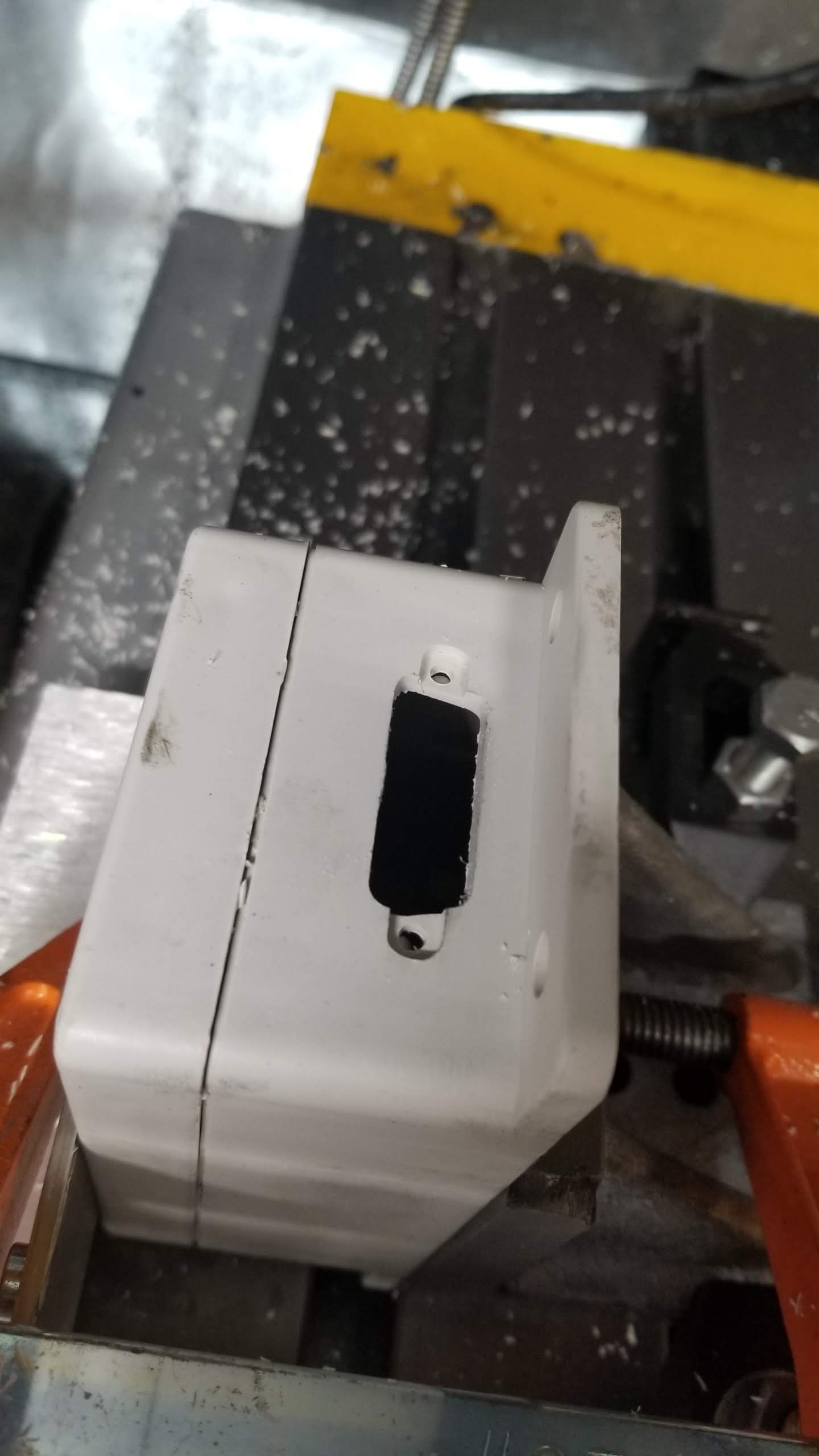
Low voltage communications are now handled with DB15 breakout. So far this has the estop and spindle pulse encoders running through it. It is wired ready for the lathe quadrature encoder and coolant solenoid. Much fun was had having my new CNC mill make a DB15 hole in the plastic box.
![]()
![]()
![]()
-
Pawn Army and Tool Setting
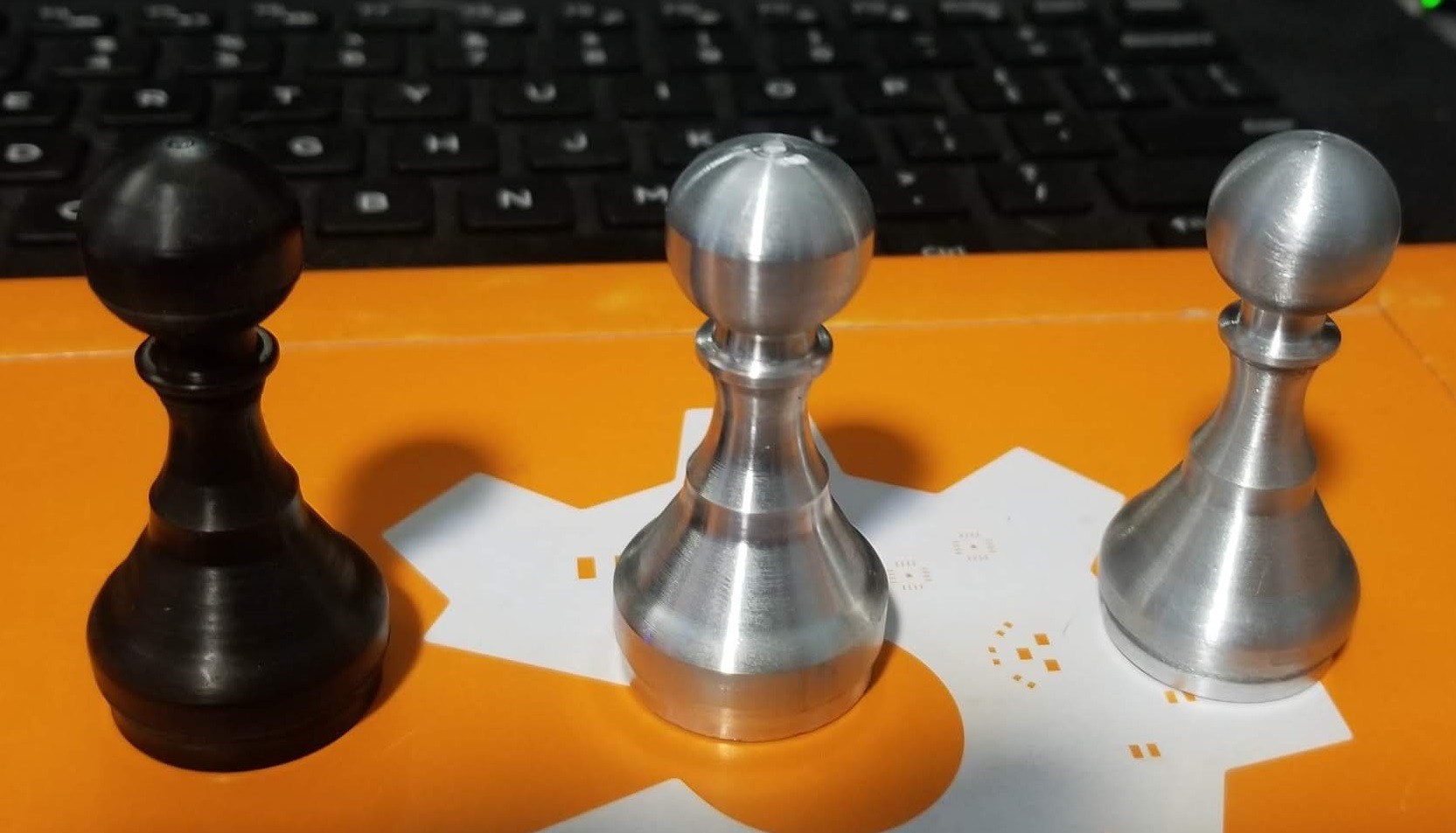
08/26/2021 at 04:04 • 0 commentsThis is the pawn from the Fusion360 CAM samples, scaled 55% to fit in the 1" stock that I have. All cut with the 2mm cutoff tool.
![]()
From left to right:0: The first attempt I had the cutoff tool programmed as 4mm width. Start again.
1: Delrin. 2mm stepover and 1200RPM. Looks pretty good.
1.9: Not shown. Aluminum same settings. Horrible screaming chatter. Then I typed G0X0 instead of G53G0X and crashed the tool into the work....
2.0 Aluminum. 540RPM. 1mm stepover. Looks pretty good. But fat. Clearly the tool moved when I crashed it. Duh. Thers a clear step in the sphere - I think because the cutoff tool end was angled not square.
3 Aluminum. Reset the tool library. Also ground the end of the tool square - it previously had a slight angle on the end for clean manual cutoffs. The end ball actually looks spherical. Happy.
I also worked out my process for tool setting.
- Mount the Fowler electronic edge finder in the chuck - gently so as not to squish it.
- Offer up the tool to the edge finder radius and jog till the light it at on/off flicker threshold.
- Jog Z+ off the end
- Jog X-0.1
- Jog Z- till we find the flicker.
- Touch off 0:0
I should be able to use this whenever I switch from mill to lathe mode too after clamping down the toolpost. (except for the 4-jaw chuck)
Shoptask 1720 LinuxCNC
Finally automating my 1998 Lathe/Mill/Drill which was built for CNC
 Alastair Young