David H Haffner Sr
-
Excel Plots for 8-Bit CCD Driver TCD1304DG Circuit Charts I & II
07/18/2017 at 12:17 • 0 commentsUPDATE
07/18/2017 11:29:AM
I wanted to add that, the objective of this post was to demonstrate a very important aspect of the scientific process; The trail of evidence, this is for those nay-sayer's who have questioned my integrity and data, I will always provide all of my processed along with all raw data, in order to provide full disclosure.
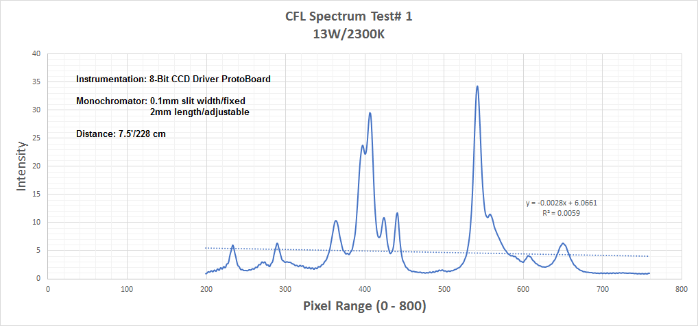
I converted the raw data from the spectral images from the other day using the formula I previously mentioned and wanted to demonstrate how it is utilized in Excel:
![]()
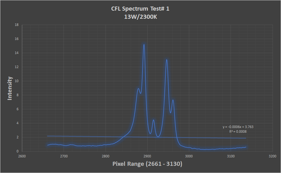
The image below is the same as above, also as of right now there is no way to calibrate the spectrum until everything is put together and tested in the enclosure and the software is updated.
![]()
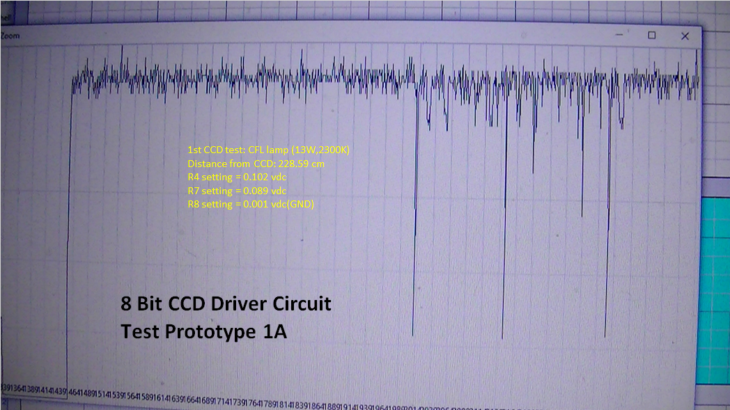
I didn't realize until I took a closer look that there must have been some light leakage in the monochromator, you'll see it in the image below:
![]()
![]()
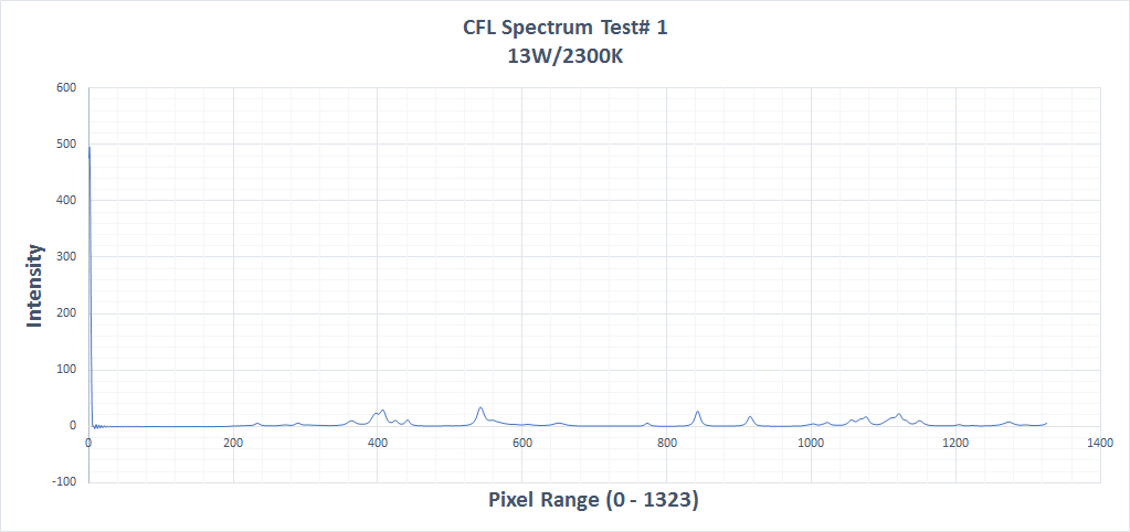
Now this is the full spectral range from 0 - 1323 pixels, you will notice at the far left of the chart a line shooting straight up the chart, this is the transmission line, which use to be the "absorption" line, by implementing this equation: (10ᶺ(-B2))*100
We can "flip" the spectral image right side up.
I am hoping that by presenting these charts and examples that it starts to bring more clarity to the complexity of this particular discipline :)
-
Description of operational aspects of the 3D printable Raman Spectrometer Operational Manual Part I
07/17/2017 at 17:05 • 0 comments07/17/2017
Description of operational aspects of the 3D printable Raman Spectrometer
Operational Manual Part I
I am including this brief explanation for some of the operational aspects of this project so it's functions and interconnectivity is less ambiguious.
There are 2 MCU's that control the units overall functions;
Arduino mega 2560
This was necessary in order to operate the turret grating mount system, by using 3 holographic diffraction gratings of various line resolutions ranging from 1200 ln's to 2400 ln/mm, a wide range of wavelengths can be achieved on the "fly" so to speak, without having to physically open the unit up and change it, who would ever want to do that?
The Mega 2560 was chosen because it is a low cost and efficient MCU with sufficient PWM and digital int pins that fit well with the design of this project.
Second, I could not drive the CCD and MTR control all with the Atmega 1284. (I tried)
Atmega 1284P
This was chosen for good reasons, the ATmega1284P is a low-power CMOS 8-bit microcontroller based on the AVR enhanced RISC architecture by executing powerful instructions in a single clock cycle, the ATmega1284P achieves throughputs approaching 1 MIPS per MHz allowing the system designer to optimize power consumption versus processing speed.
The ATmega1284P provides the following features: 128K bytes of In-System Programmable Flash with Read-While-Write capabilities, 4K bytes EEPROM, 16K bytes SRAM, 32 general purpose I/O lines, 32 general purpose working registers, Real Time Counter (RTC), three flexibleTimer/Counters with compare modes and PWM, 2 USARTs, a byte oriented 2-wire Serial Interface, a 8-channel, 10-bit ADC with optional differential input stage with programmable gain, programmable Watchdog Timer with Internal Oscillator, an SPI serial port, IEEE std. 1149.1 compliant JTAG test interface, also used for accessing the On-chip Debug system and programming and six software selectable power saving modes.
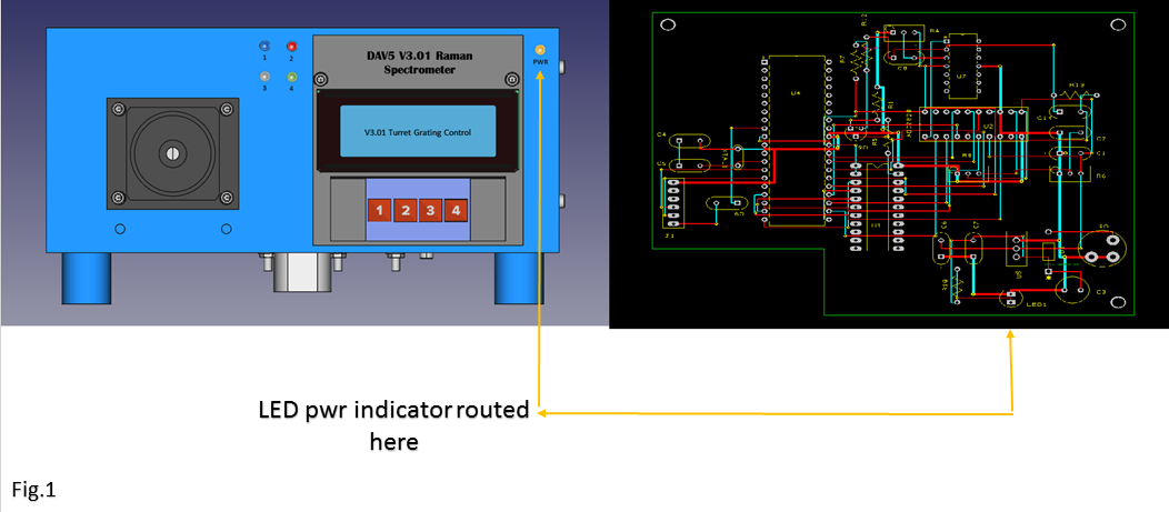
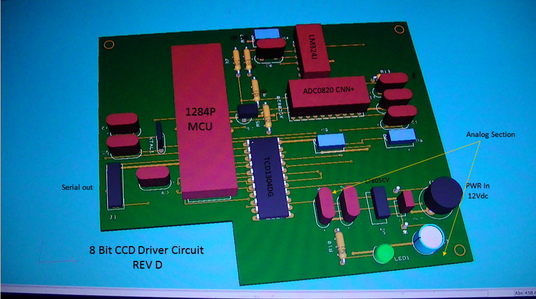
Ok, these are the brains behind the brawn of the system, in the examples below I will illustrate that the LED is not on the PCB, but routed to the front panel PWR indicator LED (yellow,) nor are the pwr plugs required on the PCB's unless you want them there, because there connections are also routed to main power.(UR only saving 0.60 cents per board?) Figure. 1 below
![]()
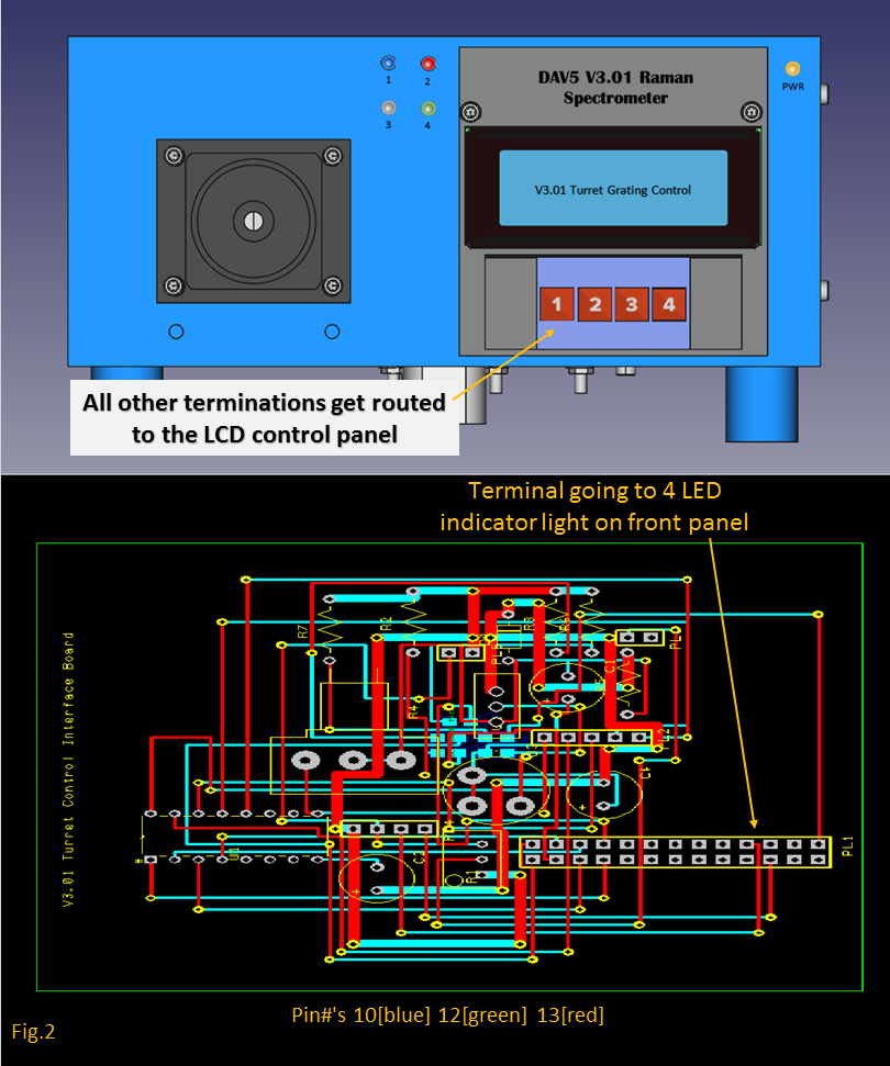
The 4 Indicator LED's to the left, are routed to the LCD control interface panel (illustrated in figure. 2
![]()
![]()
![]()
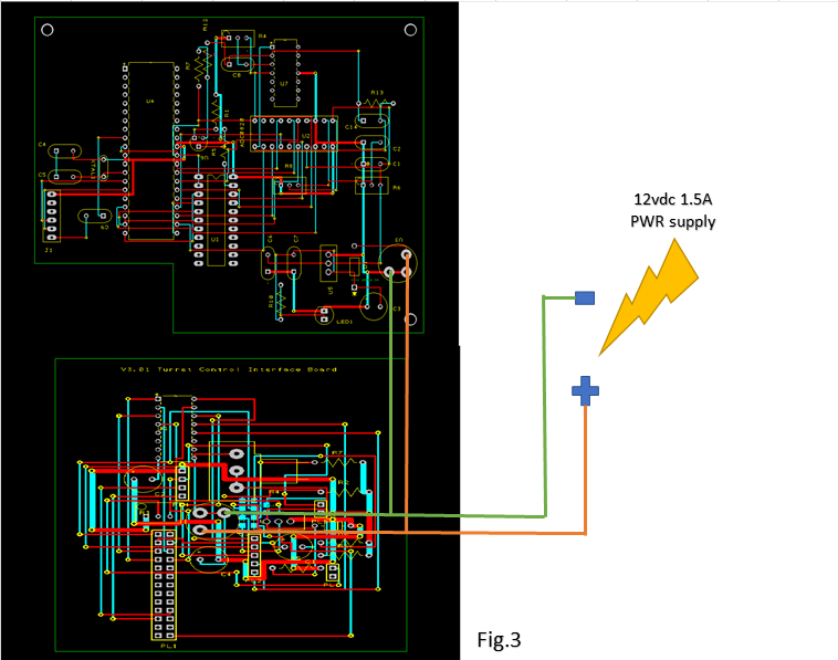
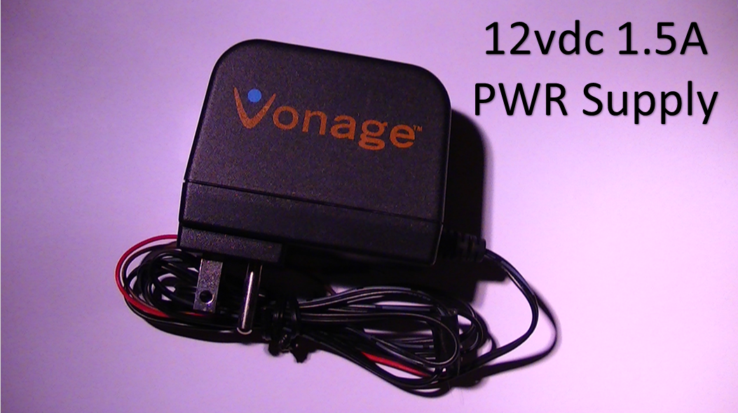
Both MCU's are routed to main PWR (12vdc 1.5A), as seen in figure. 3
![]()
The power supply may look a little odd, (it is a pwr supply from Vonage,) I had an extra one and metered it out and it was exactly 12.13 vdc, pretty darn good, and it has been operating very well for awhile now, so I trust it!
You would be surprised how many plug-in power supplies you can meter out and 99 percent of them are no where near the voltages they claim to be, (so much for the "UL" ratings...Ha ha)
Well, this concludes part I of this operation manual, I am at 95 percent project ready test mode, where the rubber really needs to hit the road...its called data!
The proof will be in the proverbial pudding :)
![]()
Part II of the operations manual will be very in depth, because it deals with the optical aspects of the design, and how there are no work around's with the quality of optical equipment used. All this will be discussed in detail in my next posting :)
-
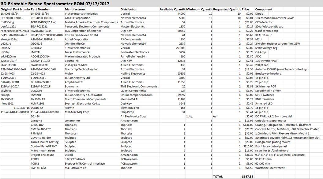
3D Printable Raman Spectrometer BOM 07/17/2017 Updated...
07/17/2017 at 10:27 • 0 commentsHere is the currently updated BOM (99%) finished for the Raman spectrometer project, there are 2 MCU's powering the unit;
- Mega 2560 R3 controls the Triple turret diffraction grating system (stepper MTR control)
- Atmega 1284P drives the CCD detector
- LCD front panel interface
- 4 button sure control
Highlights:
- Raman spectrometer for under 1K
- 65 percent 3D printed (POM or user preference)
- Field portable
- 12vdc power supply (1.5A)
- Turret mount can accommodate 3 holographic diffraction gratings
- Front panel indicator LED's
- under panel mount for Mega 2560 R3 MCU
![]()
The PCB's I get are manufactured from PCBway.com, which only cost me 5.00US for 5 boards, downside is...unless U live in China the shipping cost 27.00 :( still not too bad of a deal, the boards I have received so far have been very good and their turn around is pretty fast.
-
*UPDATED* 8 Bit CCD Driver For TCD1304DG PCB Board
07/16/2017 at 15:01 • 0 commentsWell, after careful consideration and inspection of my design I took the advice I was given and re-designed the entire circuit, I had to manually place the components on the board instead of using the auto placement feature in DesignSpark.
This may have been the problem, it arranges the components in the most optimal way yes, but does not take into account any analog to digital cross talk situations, if it does, I haven't found it, anyway's I finally got it done and did a 3D rendering also, which actually helped a lot in recognizing some further mistakes that I was able to rectify quickly.
So here it is:
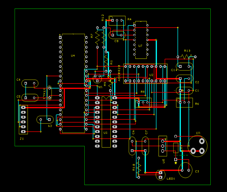
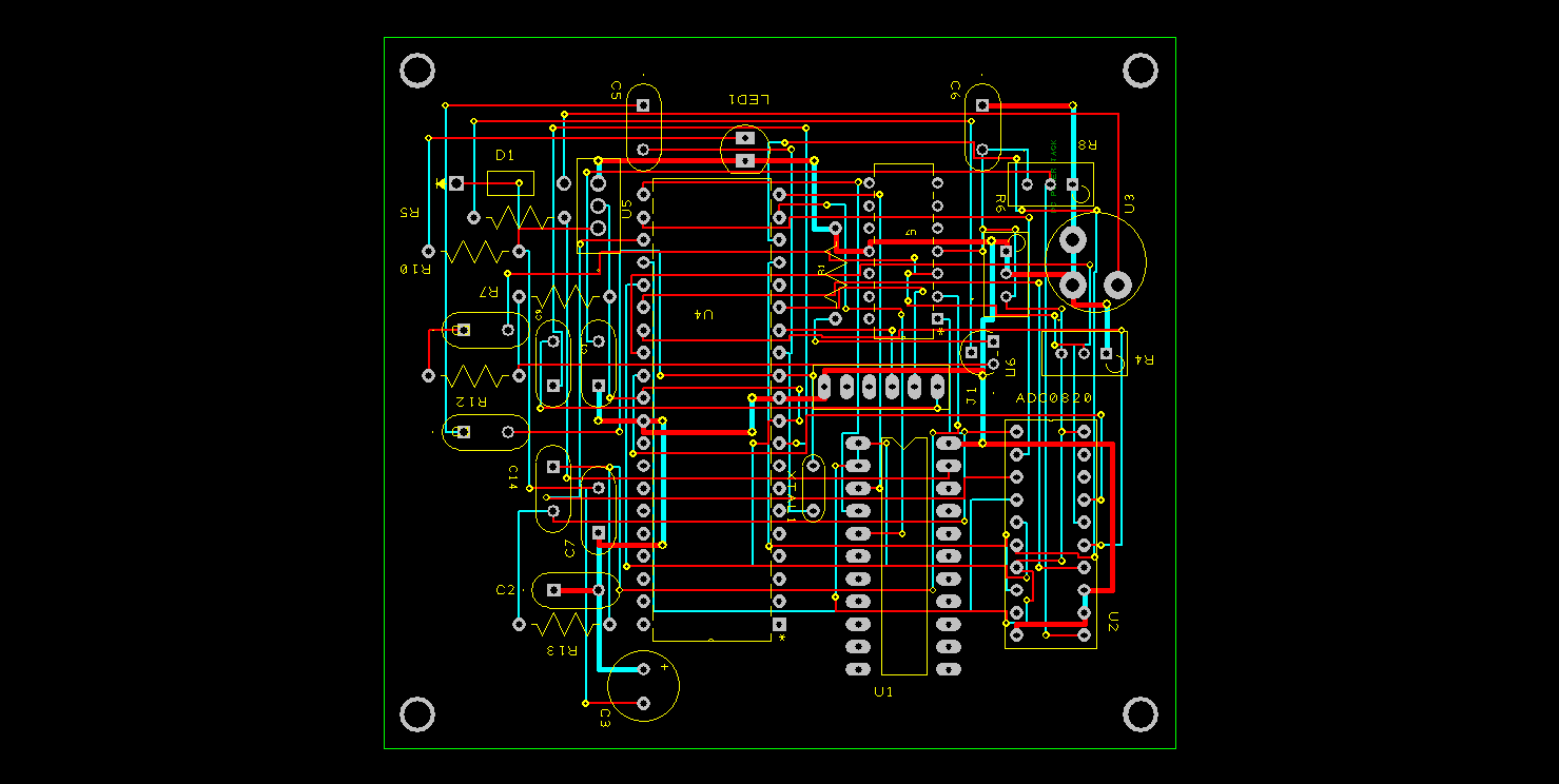
![]()
( The blue lines represent bottom copper and the red lines are top copper in the image below)
![]()
-
It Lives! 8-Bit CCD Driver Circuit TCD1304DG...
07/13/2017 at 15:44 • 0 comments*UPDATE* 07/15/2017 @ 3:14:PM
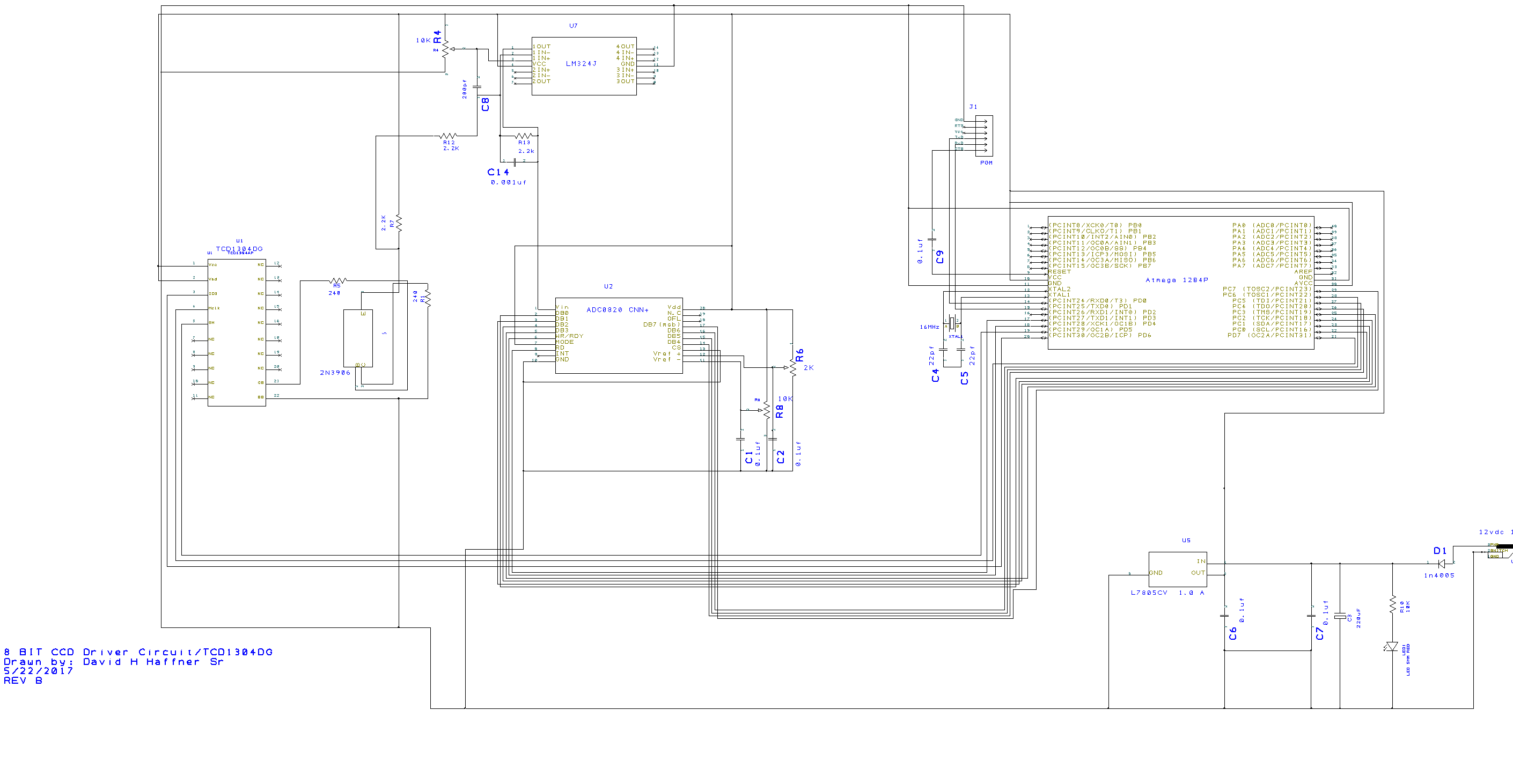
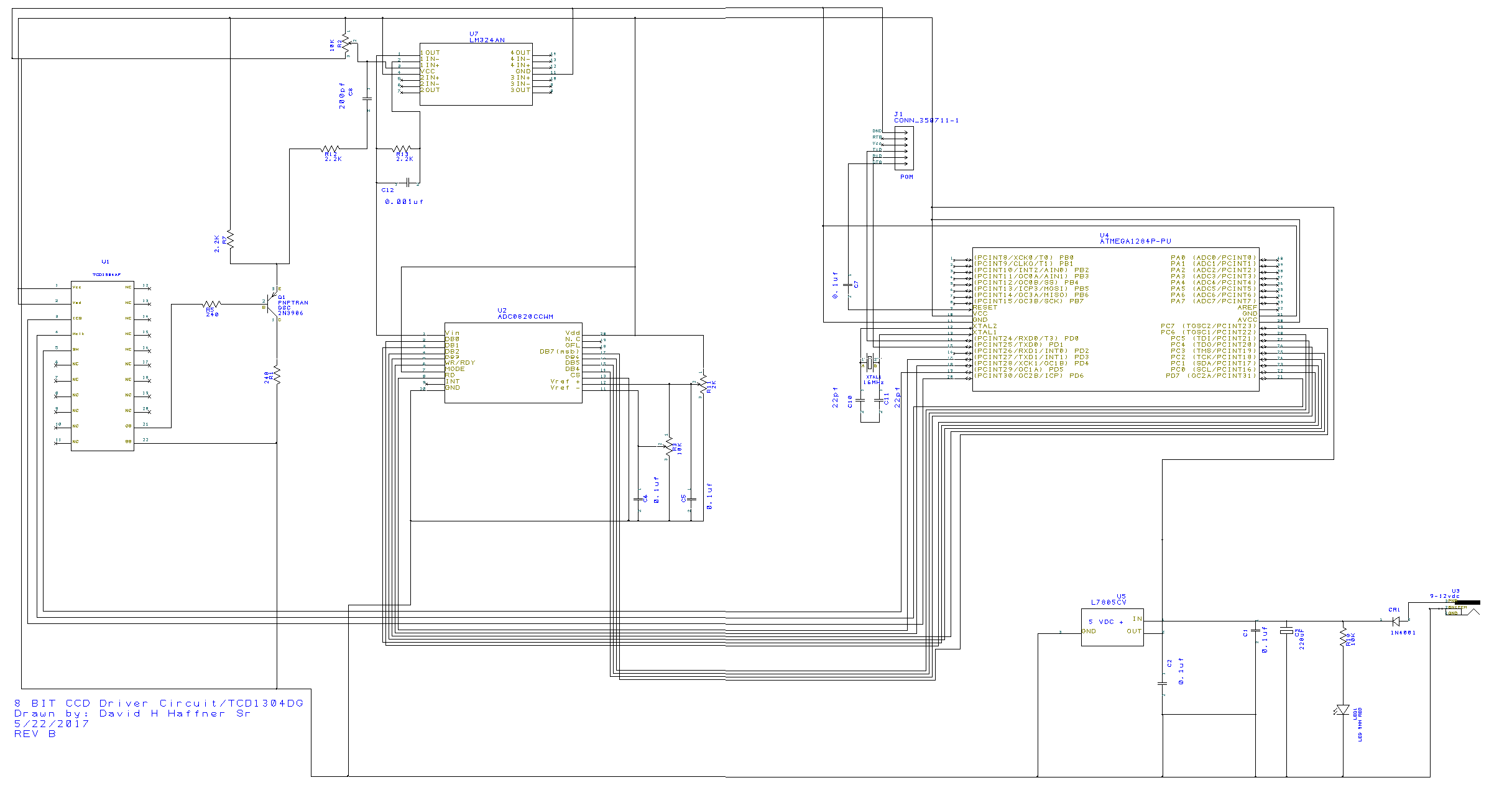
New updated schematic (8-Bit CCD driver circuit)
![]()
![]()
It was brought to my attention today that there may be some signaling and grounding problems with this design and PCB, well I cannot see them, please if anyone else can see a problem here as compared to the 4 spectral images I have posted in the last 2 days, let me know.
It was stated that I should start all over again?
Early this morning I fitted my entrance slit with a #3 variable adjusting Polarizing filter (30 mm diameter,) which I can turn from 0 deg to 360 deg open or closed depending on how much light I want to enter.
These two spectral images are the results from those tests this morning:
![]()
I used another CFL lamp with the same rating as the overhead lamp from before, only this one is portable, and as you can see from the data description it is only 8 cm from the slit, but now I can adjust the polarizing lens to let only a certain amount of light through.
Keep in mind now, that the spectral image is is not bounced off of any diffraction grating, just straight through the monochromator, this is just fine though because the slit is only 2 mm in length and a width of only 0.1mm, so the peaks are sharp and well defined.
The SNR (signal to noise ratio is well within the expected range I thought it should be in,) I will be making another post soon explaining how the SNR works and how to calculate it, it is crucial, and you need to know it :)
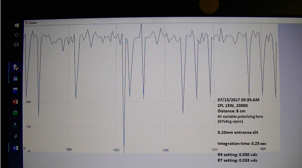
This spectral image was taken with a factor of 075 deg aperture opening.
The next spectral image panel has an aperture opening of 025 degrees;
![]()
UPDATE#2 I uploaded the fixed gerber files for PCB manufacturing.
UPDATE: I almost forgot to tell everyone, the spectral images are inverted but not to worry, this is the formula that will turn it right side up:
(10ᶺ(-B2))*100 The "-B2" is just the cell# in the second column in Excel, you would input this in that cell# and copy it down the entire path of data in that column, and it will transform the inversion to Transmission data.
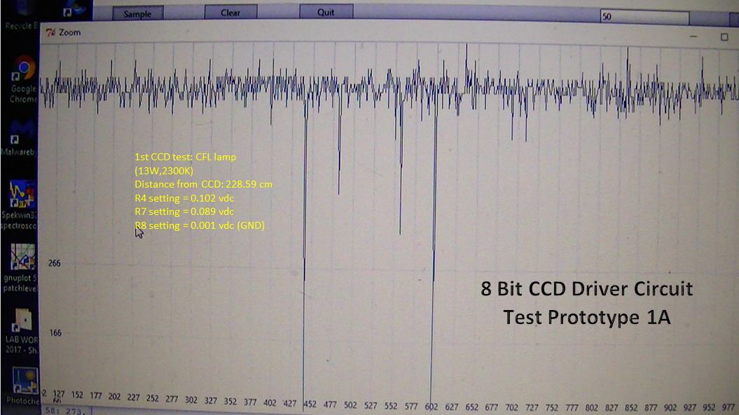
Well, it..is...ALIVE! I had to de-construct the PCB files, I made a terrible mistake that was costly, so I rebuilt the circuit on my breadboard and she runs beautifully :) I have fixed all the gerber files and will upload the updates. 1st things 1st...here are the first test spectra using a CFL lamp at 7.5ft (228.59cm) overhead room lamp:
![]()
This is the 1st test using an integration time of 0.250 sec
![]()
This is the 2nd test using an integration time of 0.5 sec
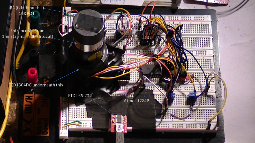
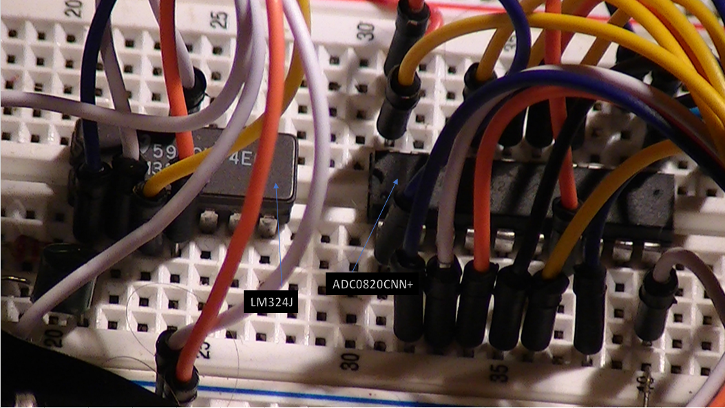
The next set if images are of the circuit build on the protoboard:
![]()
![]()
![]()
I will be uploading the PCB gerber files which are all updated and fixed up, the board dimensions are: 88.99 X 80.01 mm
Here is the updated and fixed schematic:
![]()
![]()
-
4 Button Stepper Motor Controller PCB Mistakes...
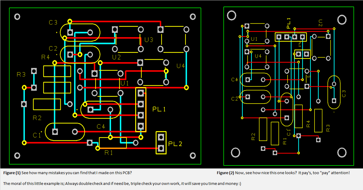
07/08/2017 at 20:42 • 0 commentsYes I make some boo-boo's on this, but thankfully didn't cost too much...
![]()
-
Stepper Motor Controller Using Arduino Mega 2560 Sec III
07/01/2017 at 12:02 • 0 commentsUpdated code can be found here: Arduino Playground Sketches/Code snippets
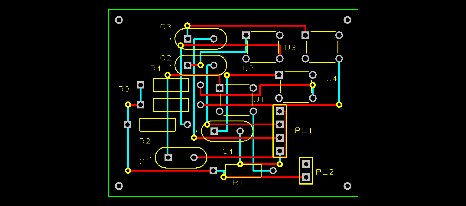
This is section 3 for the stepper motor controller interface unit, in my previous posts I had discussed and shown the use of a 1 x 4 membrane push button panel, well…at $2.00 it performed poorly so I’m not going to rely on it so I designed my own 4 button keypad on DesignSpark and the schematics are posted here.
The keypanel is being manufactured as I write this by PCBway.com.
![]()
This is my schematic design of the 4 button control key pad, dimensions: 48 x 36 mm ( 1 7/8″ x 1 7/16″.)
![]()
Above is the PCB lay out.
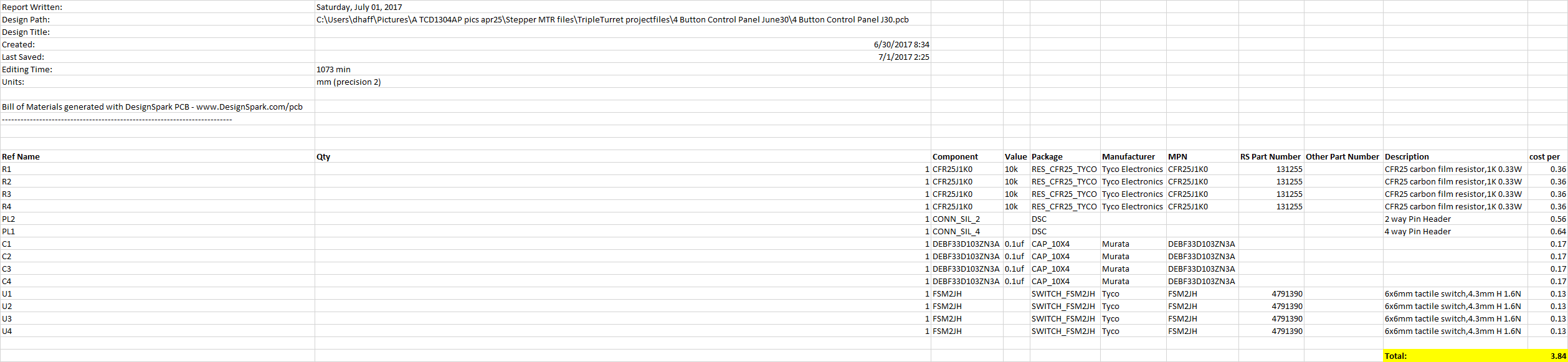
Here is the BOM (bill of materials,) which together only costs $3.84 per board to make and it is far more reliable than the membrane keypads.
![]()
This button control keypad coupled with the motor control interface module will provide superiour stepper motor performance and control, even for a low end stepper motor such as the 28YBJ-48.
This is another example I wanted to share of cost effective measures I have integrated into my overall project designs (most of the time because of budget constraints,) but I have been able to produce many high end parts that would otherwise cost many hundreds of dollars had I bought them outright.
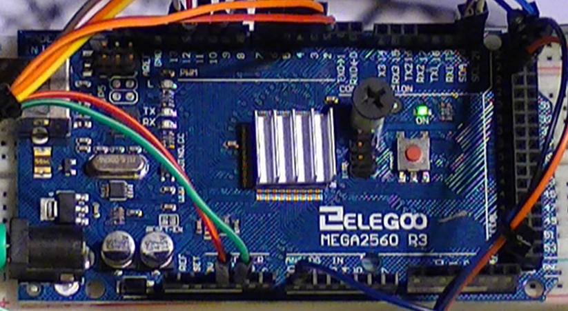
I also wanted to highlight the processor that is at the heart of all this, the Arduino Mega 2560 R3, I think this device is highly underrated and it’s versatility is really quite amazing! I like it number one, because of its a very low power consumption and extra ports, not the fastest machine around but it doesn’t need to be for the applications that are demanded of it.
Reliability and performance are far more important to me than speed.
![]()
As you might notice on mine here, I have a small 15 x 15mm aluminum heatsink on the CPU, only because I did notice that it does get a little warm now that I have her doing a lot more than usual, It does reduce overall temp by about minus 12 celsius.
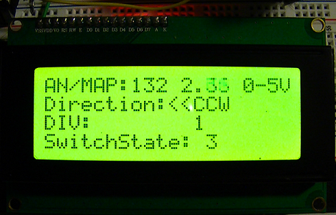
![]() Lastly, I did want to talk about some of the new features I added to the control program, as you can see on the image above to the right of the AN/Map, I added a “float” so I could read the Ref voltage from the ADC @ the stepper coils that control direction on the stepper motor. The range is from 0 to 5vdc and the readings are in real time, when the buttons are pressed the 4th line shows the button pressed and the 3rd line shows the coils activated.
Lastly, I did want to talk about some of the new features I added to the control program, as you can see on the image above to the right of the AN/Map, I added a “float” so I could read the Ref voltage from the ADC @ the stepper coils that control direction on the stepper motor. The range is from 0 to 5vdc and the readings are in real time, when the buttons are pressed the 4th line shows the button pressed and the 3rd line shows the coils activated.As the motor spins in the desired direction the voltage is shown on the AN/Map as the coils are activated. This value is controlled with a 50k trimmer POT at pin# A0, usually a 10k POT is used because of signal loss at the ADC but I have been experimenting for awhile and I am convinced that at 50k there is enough signal and very little loss at the ADC, the benefit of this is more sensitivity and better response time from the button control pad, thus a faster response at the diffraction grating turret.
Updated code can be found here: Arduino Playground Sketches/Code snippets
-
*Updated Code* For UniPolar Stepper Motor Controller ...
06/30/2017 at 22:11 • 0 commentsI incorporated a couple of code changes to the stepper MTR program, one is, now when a button is pressed U can see the voltage displayed on Ln 1 of the LCD in real time, reading is taken from A0 via the ADC/mapping of the directional coils controlling direction.
2nd change is, a 50K trimmer POT, yes I experimented enough and I am convinced that this is the right value and setting for the functions that this stepper MTR program needs to perform.
Here is the code:
#include <LiquidCrystal_I2C.h>
#include <Wire.h>
/* Program 1 REV B
Updated 6/30/2017 @ 5:30:PM
Code concept and project design by David H Haffner Sr.
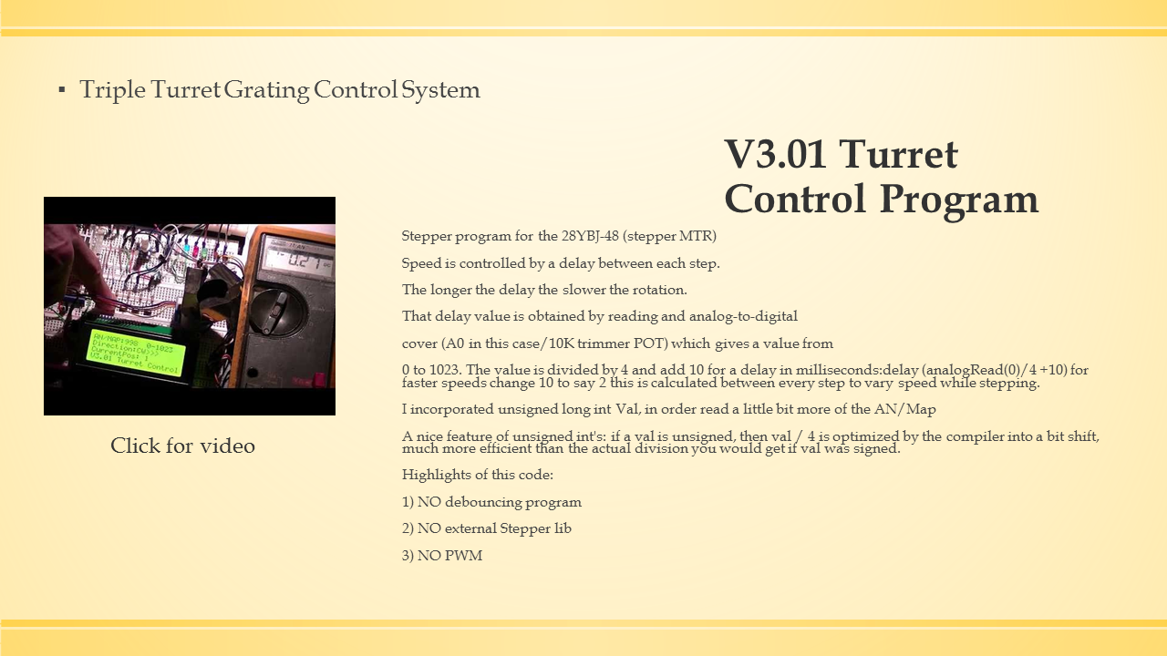
Stepper program for the 28YBJ-48 (stepper MTR) and ULN2003 driver
This particular stepper motor is 5.625 degrees per step
/64
Speed is controlled by a delay between each step.
The longer the delay the slower the rotation.
That delay value is obtained by reading and analog-to-digital
cover (A0 in this case/50K trimmer POT) which gives a value from 0 to 1023.
The value is divided by 4 and add 10 for a delay
in milliseconds:delay(analogRead(0)/4 +10)
For faster speeds change 10 to say 2.
This is calculated between every step to vary speed while stepping.
I incorporated unsigned long int Val, in order read a little bit more of the AN/Map
A nice feature of unsigned ints: if a val is unsigned, then val / 4 is optimized by
the compiler into a bit shift, much more efficient than the actual division you would
get if val was signed.
Further incorporated a pin array;//read the pushbutton value into a variable
int sensorVal[] = { digitalRead [2][3] };//SW1 pin2 & SW2 pin3
This will illuminat LED's #10(W) and LED #12(bl) to indicate that the switches
on HIGH. These values are then displayed on the LCD menu on line 3 as a monitor
of the switches values.
// set the LCD address to 0x27 or 0x3F for a 20 chars 4 line display
// Set the pins on the I2C chip used for LCD connections:
// addr, en,rw,rs,d4,d5,d6,d7,bl,blpol
The commands below will be compiled into machine code and uploaded
to the microcontroller.
This is in the public domain.
Compiled size 6646 bytes.
*/
const int yellow = 7; // M1
const int orange = 5; // M2
const int brown = 6; // M3
const int blue = 4; // M4
const int CW = 2; //Sw1 in schematic
const int CCW = 3; //Sw2 in schematic
unsigned long int val = (analogRead(A0) / 4 + 10);
unsigned long int val1 = (analogRead('...') * 4 + 2);// scale it to use it with the MTR (value between 0 and 175)
LiquidCrystal_I2C lcd(0x3F, 2, 1, 0, 4, 5, 6, 7, 3, POSITIVE); // Set the LCD I2C address
void setup() {
// initialize digital pin LED_BUILTIN (13) as an output.
pinMode(LED_BUILTIN, OUTPUT);//Modified "blink" sequence (2)millisec in-step/W/MTR sequence
pinMode(10, OUTPUT);// this is the LED pin for sensor val prgm
pinMode(12, OUTPUT);// this is for LED pin 12 sensor Val prgm
digitalWrite(CW, 1); // pull up on
digitalWrite(CCW, 1); // pull up on
pinMode(blue, OUTPUT);
pinMode(brown, OUTPUT);
pinMode(orange, OUTPUT);
pinMode(yellow, OUTPUT);
// all coils off
digitalWrite(blue, 0);
digitalWrite(brown, 0);
digitalWrite(orange, 0);
digitalWrite(yellow, 0);
lcd.begin(20, 4); // initialize the lcd for 20 chars 4 lines, turn on backlight
// ------- Quick 3 blinks of backlight -------------
for (int i = 0; i < 3; i++)
{
lcd.backlight();
delay(250);
lcd.noBacklight();
delay(250);
}
lcd.backlight(); // finish with backlight on
// set up the LCD's number of columns and rows:
lcd.begin(20, 4);
// Print a message to the LCD.
lcd.print("AN/MAP:");
lcd.setCursor(16, 0);
lcd.print("0-5V");
lcd.setCursor(0, 1);
lcd.print("Direction:");//CCW or CC
lcd.setCursor(0, 3);
lcd.print("SwitchState:");//4th line for version display
lcd.setCursor(0, 2);
lcd.print("DIV:");
Serial.begin(115200);
}
void loop() {
// read the input on :
for (int i = 0; i < 6; i++) {
val1 = analogRead(i);
delay(10);
// Convert the analog reading (which goes from 0 - 1023) to voltage range (0 - 5V);
float voltage0 = val1 * (5.0 / 1023.0);
// print out the value you read:
Serial.print(voltage0); Serial.print("i =");
Serial.print(i); Serial.print(";");
if (i == 5) Serial.println(" ");
lcd.setCursor(11, 0);
lcd.print(voltage0);//reads the current Voltage from A0
}
if (!digitalRead(CW)) {
forward(10);
all_coils_off();
lcd.setCursor(13, 3);// set Cursor at place 12, 3
lcd.print(CW);
}
if (!digitalRead(CCW)) {
reverse(10);
all_coils_off();
lcd.setCursor(13, 3);// set Cursor at place 12, 3
lcd.print(CCW);
}
{
digitalWrite(LED_BUILTIN, HIGH); // When button is pressed, moves MTR same# of steps as LED timing sequence
delay(1); // wait for a second
digitalWrite(LED_BUILTIN, LOW); //
delay(1); // wait for a second
}
//read the pushbutton value into a variable
int sensorVal_1 = digitalRead(CW);//SW pin
//print out the value of the pushbutton
Serial.println(sensorVal_1);
// Keep in mind the pullup means the pushbutton's
// logic is inverted. It goes HIGH when it's open,
// and LOW when it's pressed. Turn on LED pin when the
// button's pressed, and off when it's not:
if (sensorVal_1 == HIGH) {
digitalWrite(10, LOW);//LED pin
} else {
digitalWrite(10, HIGH);//LED pin
}
//read the pushbutton value into a variable
int sensorVal_2 = digitalRead(CCW);//SW pin
//print out the value of the pushbutton
Serial.println(sensorVal_2);
// Keep in mind the pullup means the pushbutton's
// logic is inverted. It goes HIGH when it's open,
// and LOW when it's pressed. Turn on LED pin when the
// button's pressed, and off when it's not:
if (sensorVal_2 == HIGH) {
digitalWrite(12, LOW);//LED pin
} else {
digitalWrite(12, HIGH);//LED pin
}
for (int i = 0; i <= 10; i++)//This keeps LED indicator LED pin on high until button is pressed
{ //then blinks in sync with rotation of motor until released
(analogRead(A0) / 4 + 10);
}
val1 = (analogRead(val1) * 4 + 2); //scale it to use it with the stepper mtr (value between 0 and 175)
} // end loop
void all_coils_off(void) {
digitalWrite(blue, 0);
digitalWrite(brown, 0);
digitalWrite(orange, 0);
digitalWrite(yellow, 0);
}
void reverse(int i) {
{
lcd.setCursor(10, 1);
lcd.print("<<CCW");
}
while (1) {
digitalWrite(blue, 1);
digitalWrite(brown, 0);
digitalWrite(orange, 1);
digitalWrite(yellow, 0);
delay(analogRead(A0) / 4 + 10);
i--;
if (i < 1) break;
{
lcd.setCursor(12, 2);//print out the value of the pushbutton
lcd.print(i--);
}
digitalWrite(blue, 0);
digitalWrite(brown, 1);
digitalWrite(orange, 1);
digitalWrite(yellow, 0);
delay(analogRead(A0) / 4 + 10);
i--;
if (i < 1) break;
{
lcd.setCursor(7, 0);
lcd.print(analogRead(i--) / 4 + 10);
}
digitalWrite(blue, 0);
digitalWrite(brown, 1);
digitalWrite(orange, 0);
digitalWrite(yellow, 1);
delay(analogRead(A0) / 4 + 10);
i--;
if (i < 1) break;
{
lcd.setCursor(12, 2);//print out the value of the pushbutton
lcd.print(i--);
}
digitalWrite(blue, 1);
digitalWrite(brown, 0);
digitalWrite(orange, 0);
digitalWrite(yellow, 1);
delay(analogRead(A0) / 4 + 10);
i--;
if (i < 1) break;
{
lcd.setCursor(12, 2);//print out the value of the pushbutton
lcd.print(i--);
}
}
}
void forward(int i) {
{
lcd.setCursor(10, 1);
lcd.print("CW>>>");
}
while (1) {
digitalWrite(blue, 1);
digitalWrite(brown, 0);
digitalWrite(orange, 0);
digitalWrite(yellow, 1);
delay(analogRead(A0) / 4 + 10);
i--;
if (i < 1) break;
{
lcd.setCursor(12, 2);//print out the value of the pushbutton
lcd.print(i--);
}
digitalWrite(blue, 0);
digitalWrite(brown, 1);
digitalWrite(orange, 0);
digitalWrite(yellow, 1);
delay(analogRead(A0) / 4 + 10);
i--;
if (i < 1) break;
{
lcd.setCursor(12, 2);//print out the value of the pushbutton
lcd.print(i--);
}
digitalWrite(blue, 0);
digitalWrite(brown, 1);
digitalWrite(orange, 1);
digitalWrite(yellow, 0);
delay(analogRead(A0) / 4 + 10);
i--;
if (i < 1) break;
{
lcd.setCursor(12, 2);//print out the value of the pushbutton
lcd.print(i--);
}
digitalWrite(blue, 1);
digitalWrite(brown, 0);
digitalWrite(orange, 1);
digitalWrite(yellow, 0);
delay(analogRead(A0) / 4 + 10);
i--;
if (i < 1) break;
{
lcd.setCursor(12, 2);//print out the value of the pushbutton
lcd.print(i--);
}
}
}
-
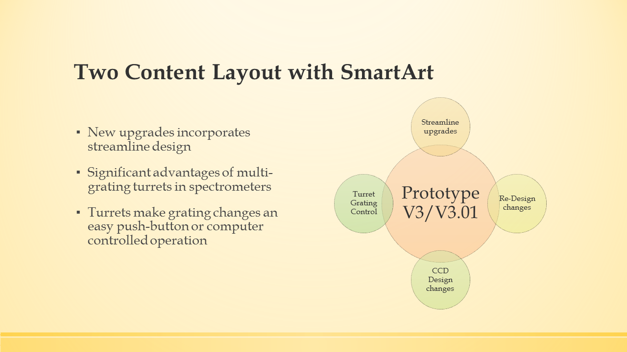
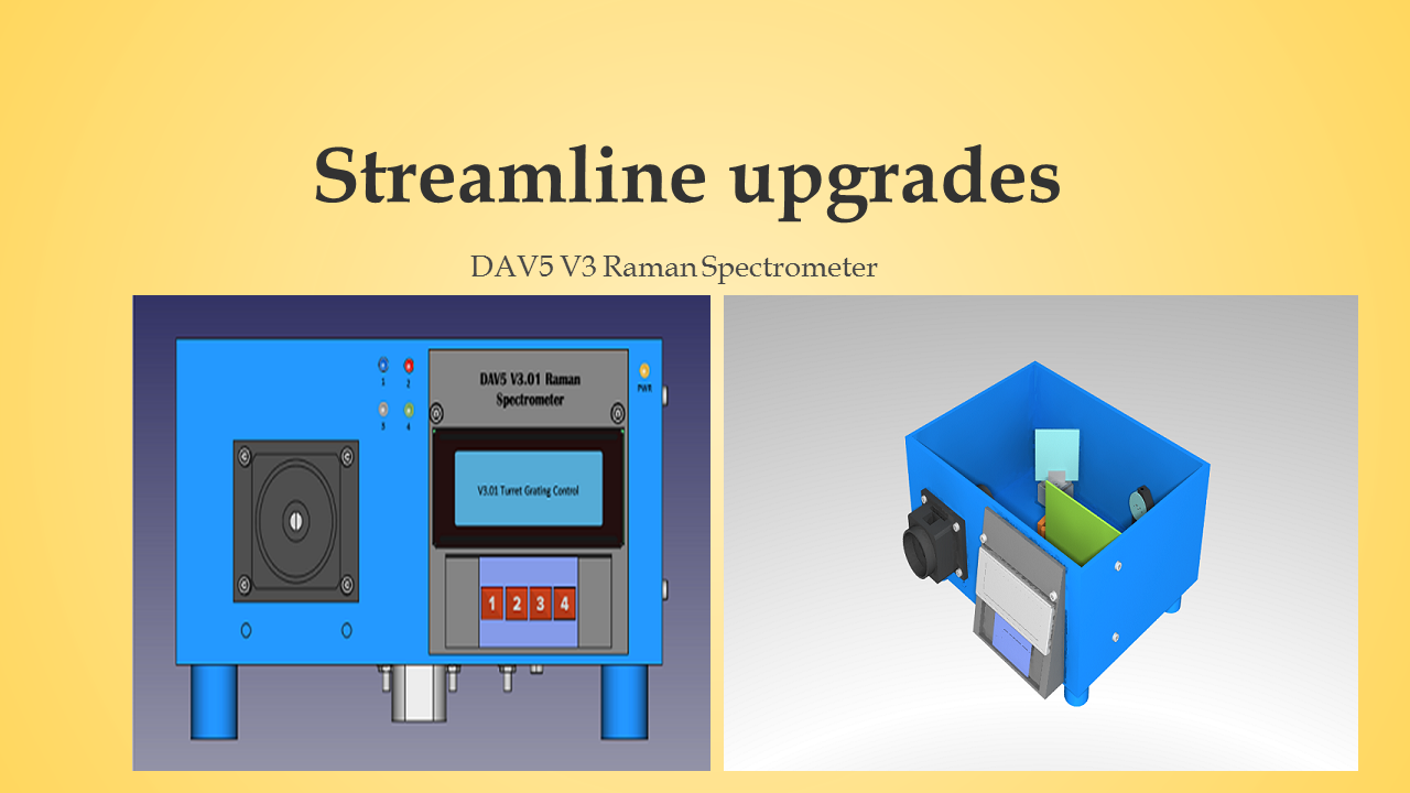
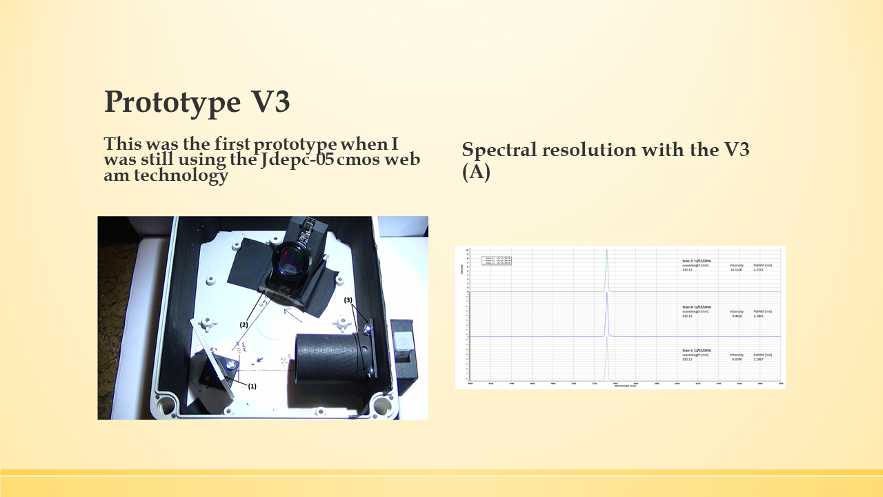
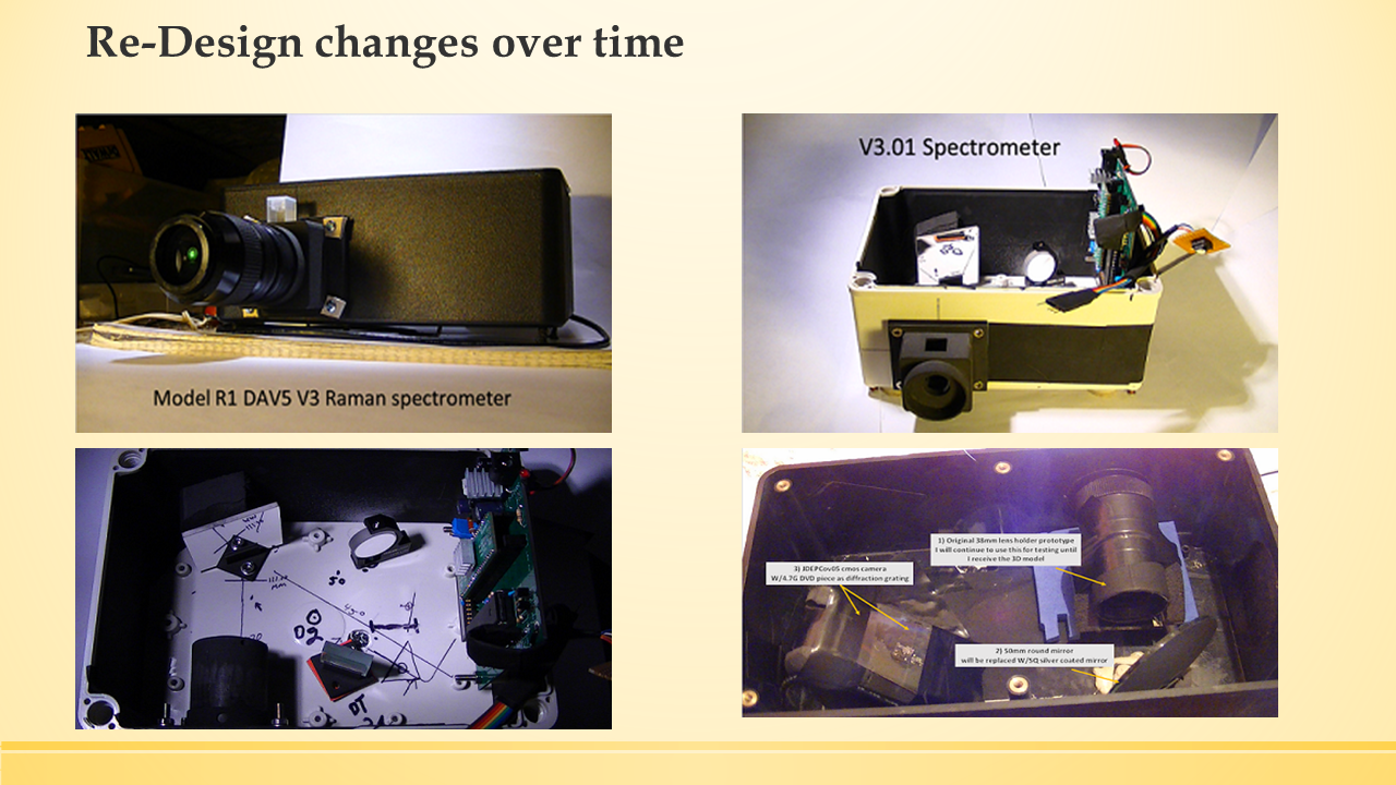
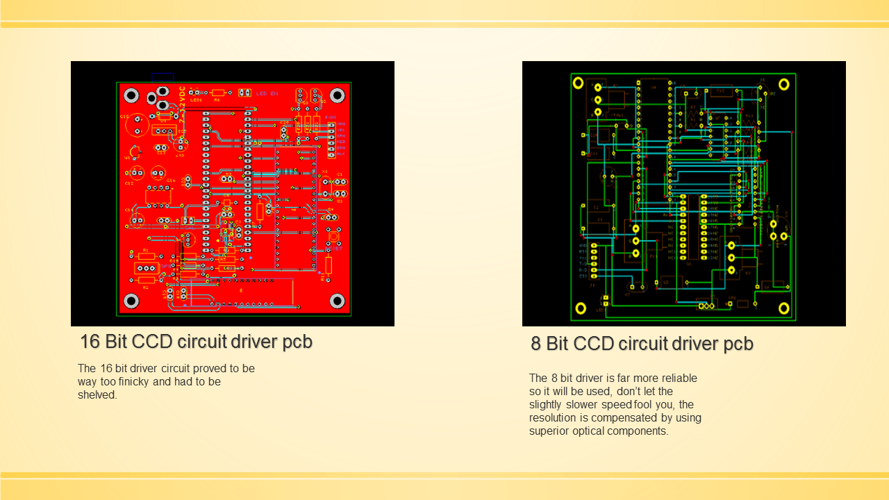
PowerPoint Presentation/DAV5 V3.01 Raman Spectrometer
06/26/2017 at 14:05 • 0 commentsPowerPoint presentation:
V3.01 3D printable Raman Spectrometer Updated (when available)
![]()
![]()
![]()
![]()
![]()
![]()
![]()
![]()
![]()
*note, in this case we are bypassing the exit slit by incorporating the triple turret system which gives us absolute control over wavelength selection.
-
1 X 4 KeyPad Matrix & LCD Display Control Console
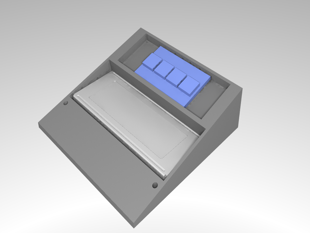
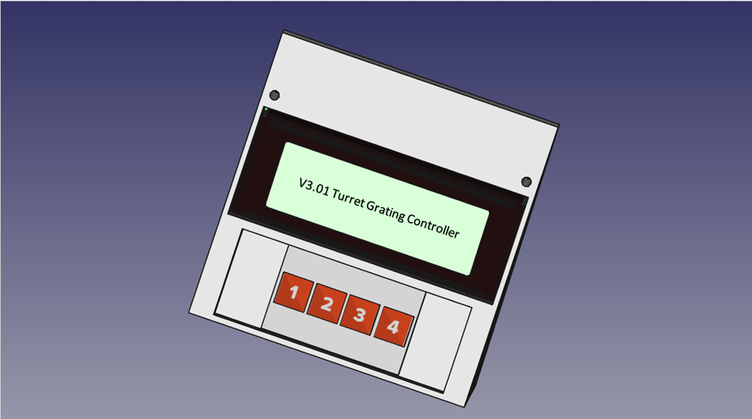
06/23/2017 at 11:47 • 0 commentsThis is the control console for the DAV5 V3.01 Raman spectrometer, I designed it on FreeCad v0.16. I will be having this 3d printed by Sculpteo using POM material (powdered nylon type material,) color [white] for about $107.00US, as always, all my 3d parts are manufactured by Sculpteo and I have over 236 designs uploaded to their website at my personal shop their.
This console utilizes a 1 x 4 keypad matrix # pad, to control the functions of the diffraction grating that is mounted on the triple turret.
![]()
![]()
![]()
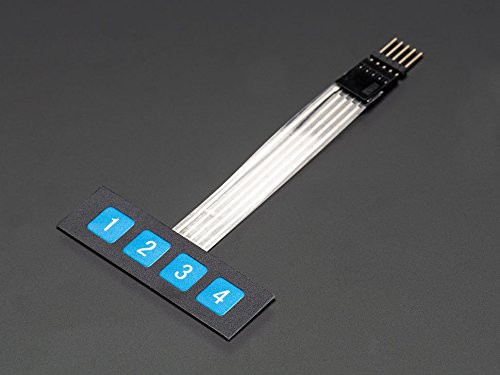
Adafruit Membrane 1x4 Keypad
This keypad has 4 buttons, and since every key has its own wire line, no matrix code is required - just treat these like every day switches. The membrane is soft and has a removable paper backing to expose a strong adhesive so you can stick this on an enclosure and feed the cable through a slot.
Dimensions 2 x 1.2 x 0.1 inches
DAV5 V3.01 Raman Spectrometer
The only thing worth doing, is the thing worth doing right!