David H Haffner Sr
-
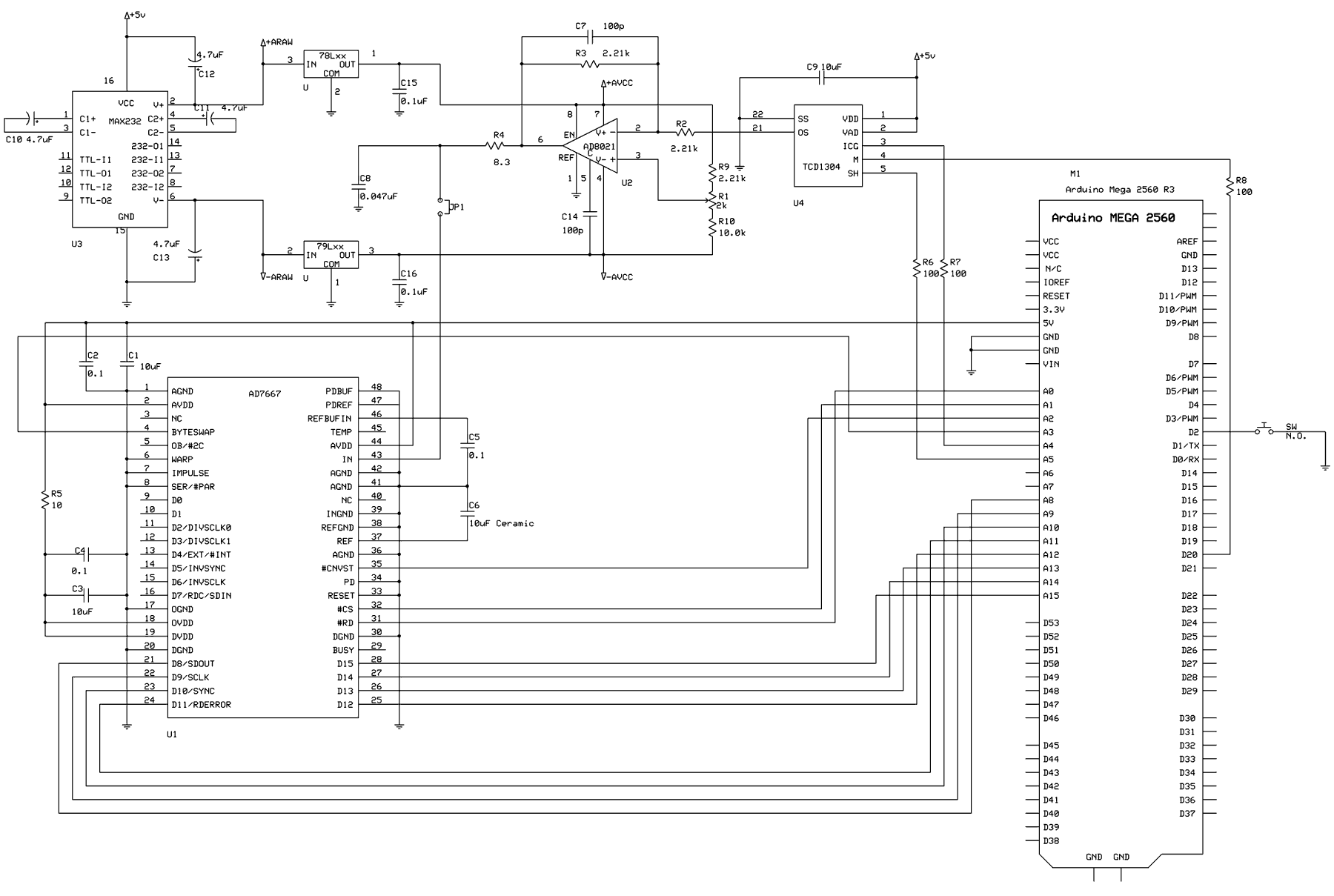
16 Bit AD7667-ADC/MAX232/AD8021 Driving The TCD1304AP CCD chip...
02/11/2017 at 14:25 • 0 commentsAfter listening to some very wise counsel here at Hackaday, (thanks @Ted Yapo and @K.C.Lee,) I have decided to go full blown and build the 16 bit CCD driver. This will drive the over all cost up a bit but in the long run its worth the investment.
I would also encourage everyone reading this post to please take a little time and read my new blog at http://dhaffnersr.blog/
The reason is, it will explain why I have to do things in a certain way and in a certain order (I know it seems odd, but after reading my blog you will understand.)Here is the new schematic and code;
![]()
16 bit version
#include <util/delay_basic.h>
#define RD (1<<0)
#define CS (1<<1)
#define CNVST (1<<2)
#define BYTESWAP (1<<3)
#define ICG (1<<4)
#define SH (1<<5)
#define MCLK (1<<6)
// Full frame, including dark pixels
// and dead pixels.
#define PIXEL_COUNT 3800
#define CLOCKS PORTF
#define CLOCKS_DDR DDRF
#define DATA_PINS PINK
#define DATA_PORT PORTK
#define DATA_DDR DDRK
// 10mS exposure time.
#define EXPOSURE_TIME 1
// Initial clock state.
uint8_t clocks0 = (RD + CS + CNVST + ICG);
// 16-bit pixel buffer
uint16_t pixBuf[PIXEL_COUNT];
/*
* readLine() Reads all pixels into a buffer.
*/
void readLine()
{
// Get an 8-bit pointer to the 16-bit buffer.
uint8_t * buf = (uint8_t *)pixBuf;
int x;
cli();
CLOCKS |= (RD + CS + CNVST + ICG + BYTESWAP + SH);
OCR2A = 5;
TCNT2 = 0;
PORTB &= ~0x02;
for (x = 0; x < PIXEL_COUNT; ++x)
{
CLOCKS ^= SH;
CLOCKS &= ~CNVST;
CLOCKS |= CNVST;
_delay_loop_1(4);
__asm__("nop\n\t");
__asm__("nop\n\t");
__asm__("nop\n\t");
CLOCKS ^= SH;
CLOCKS &= ~(CS + RD);
*buf++ = DATA_PINS;
CLOCKS &= ~(BYTESWAP);
*buf++ = DATA_PINS;
CLOCKS |= (RD + CS + BYTESWAP);
}
sei();
}
/*
* startLine() Toggles the clocks to shift the line
* into the CCD shift register.
*/
void startLine()
{
// Set ICG low.
CLOCKS &= ~ICG;
_delay_loop_1(5);
// Set SH high.
CLOCKS |= SH;
_delay_loop_1(5); // 10uS.
// Set SH low.
CLOCKS &= ~SH;
_delay_loop_1(10);
// Set ICG high.
CLOCKS |= ICG;
}
/*
* sendLine() Send the line of pixels to the user.
*/
void sendLine()
{
int x;
for (x = 0; x < PIXEL_COUNT; ++x)
{
Serial.println(pixBuf[x]);
}
}
/*
* cleanLine() Performs voodoo on the data.
* Looks for shot noise and replaces it with
* the previous pixel data. You might want to
* skip this if doing serious science. The blip
* might be your data.
*/
void cleanLine()
{
int x, fixes = 0;
for (x = 1; x < PIXEL_COUNT; ++x)
{
if (pixBuf[x] > (int)(pixBuf[x - 1] * 1.1))
{
if (++fixes < 10)
pixBuf[x] = pixBuf[x - 1];
}
else if (pixBuf[x] < (int)(pixBuf[x - 1] * 0.9))
{
if (++fixes < 10)
pixBuf[x] = pixBuf[x - 1];
}
else
{
fixes = 0;
}
}
}
/*
* setup()
* Set the data port to input.
* Set the clock port to output.
* Start timer2 generating the Mclk signal
* Set the pullup on pin 2 for the start switch.
*/
void setup() {
CLOCKS_DDR = 0xff;
CLOCKS = clocks0;
DATA_DDR = 0x0;
Serial.begin(115200);
// Setup timer2 to generate a 1.333MHz frequency on D10
TCCR2A = (0 << COM2A1) | (1 << COM2A0) | (1 << WGM21) | (0 << WGM20);
TCCR2B = (0 << WGM22) | (1 << CS20);
// "5" causes 6 intervals - 0 through 5
OCR2A = 5;
TCNT2 = 0;
// Output Mclk on D2
DDRB |= 0x10;
// For the trigger switch.
pinMode(2, INPUT_PULLUP);
}
/*
* loop()
* Read the CCD continuously.
* Upload to user on switch press.
*/
void loop() {
startLine();
readLine();
delay(EXPOSURE_TIME);
if (!digitalRead(2))
{
cleanLine();
sendLine();
}
}
-
Using An Arduino R3 to power the TCD1304AP CCD chip...
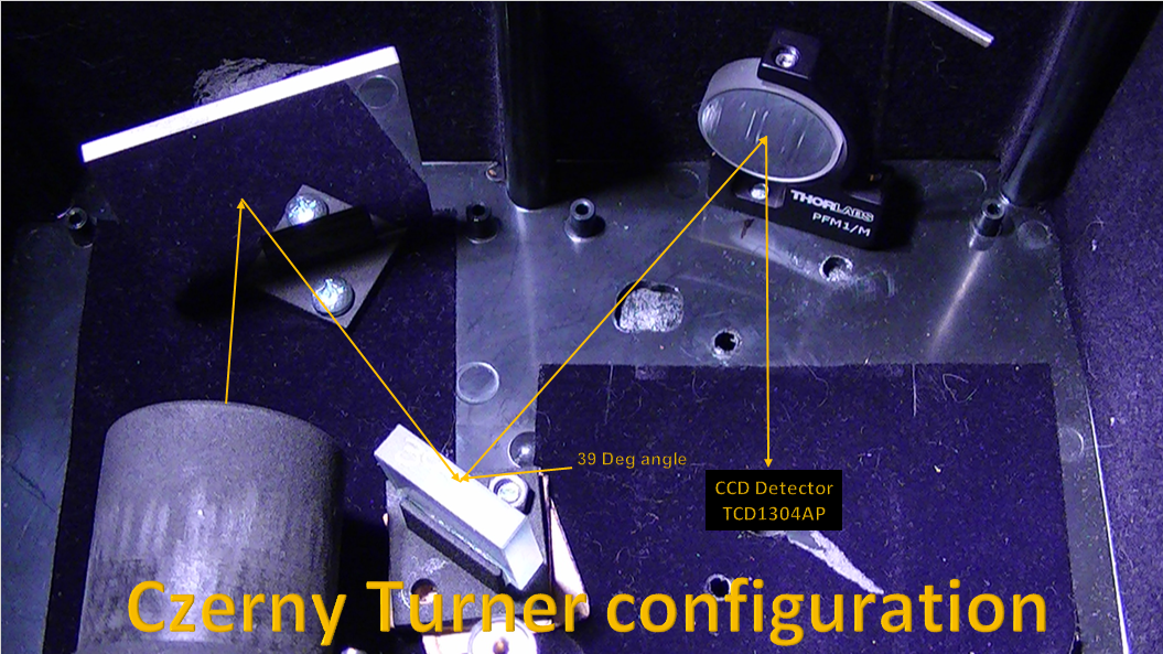
02/09/2017 at 16:33 • 22 commentsI am never too proud to admit when I have "hit" the proverbial brick wall of discovery, I have, with the concept of using the JDEPC-05 cmos camera as the detector for this project. The cmos chip will not work with this configuration, I understand now why, (duh...) I should have known this from the start a year ago, as soon as I got the diffraction grating and second mirror aligned, it was like magic, a very nice, visable spectral line.
The problem was, it was approx. 50mm wide. That's when I realized my error, "spectral dispersion", the reason the DVD or holographic sheet works with the cmos type camera is because of incident light dispersion. The spectral "beam" does not "fit" correctly with the incident angle of the cmos camera lens, and consequently, the cmos camera will not work without the lens focusing the light image!
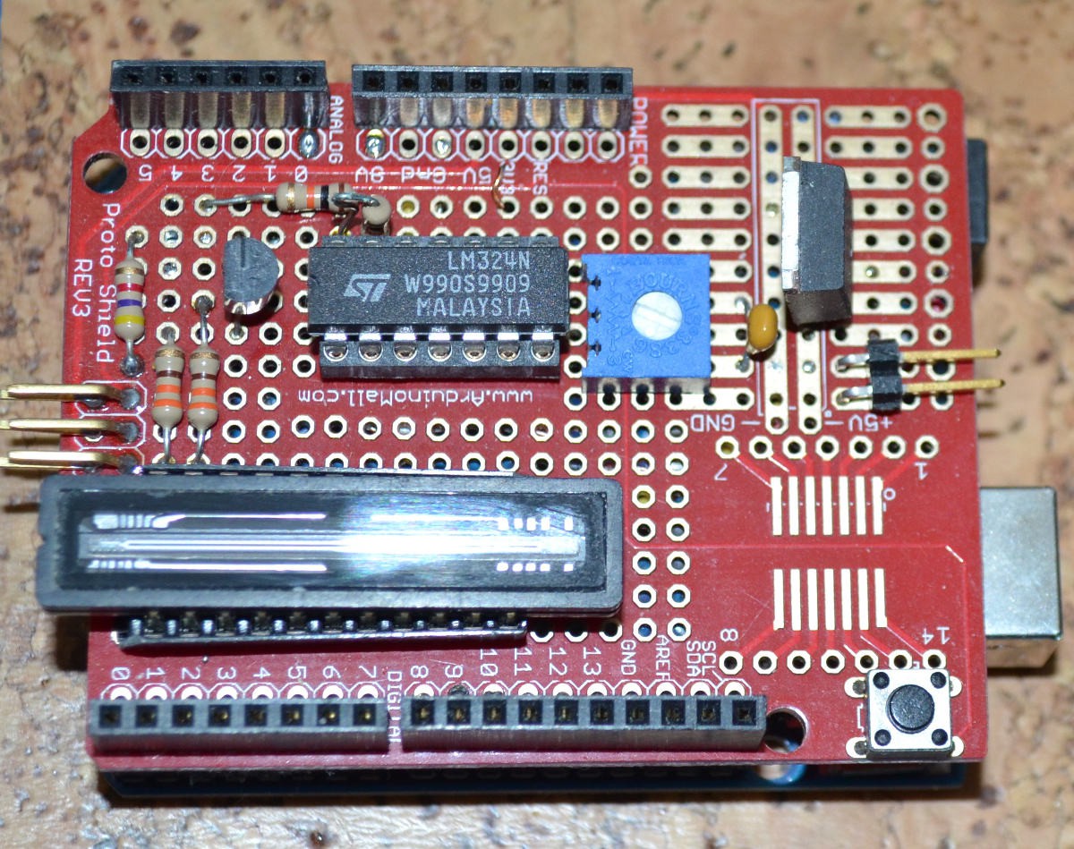
So...I am making a hybrid of http://hackaday.io/project/9829-linear-ccd-module, the one esben rossel made, I'll be using an Arduino R3 as the micro processor to run the TCD1304 linear CCD chip.
I am posting the schematics for the circuit design and protoboard pics (which are from David Allmon, http://davidallmon.com/pages/ccd-transmission-spectrograph) this is the 10 bit version of the controller, there is a 16 bit version which is available, but I want to build this one first and test it out before delving into the 16 bit controller.
Also I am posting the micro controller software code;
![]()
![]() *note, disregard the lamp part of the schematic as it is not required, only the controller is.
*note, disregard the lamp part of the schematic as it is not required, only the controller is.![]() #include <util/delay_basic.h>
#include <util/delay_basic.h>#ifdef ARDUINO_AVR_MEGA2560
#define LAMP 0x20
#define SH 0x40
#define ICG 0x80
#define MCLK 0x10
#else
#define LAMP 0x01
#define SH 0x02
#define ICG 0x04
#define MCLK 0x08
#endif
#define CLOCK PORTB
uint8_t buffer[800];
uint8_t avg = 0;
char cmdBuffer[16];
int cmdIndex;
int exposureTime = 20;
void setup()
{
uint8_t val;
// Initialize the clocks.
DDRB |= (LAMP | SH | ICG | MCLK); // Set the clock lines to outputs
CLOCK |= ICG; // Set the integration clear gate high.
// Enable the serial port.
Serial.begin(115200);
// Setup timer2 to generate a 470kHz frequency on D11
TCCR2A = + (0 << COM2A1) | (1 << COM2A0) | (1 << WGM21) | (0 << WGM20);
TCCR2B = (0 << WGM22) | (1 << CS20);
OCR2A = 20;
TCNT2 = 1;
// Set the ADC clock to sysclk/32
ADCSRA &= ~((1 << ADPS2) | (1 << ADPS1) | (1 << ADPS0));
ADCSRA |= (1 << ADPS2) | (1 << ADPS0);
}
void readCCD(void)
{
int x;
uint8_t result;
CLOCK &= ~ICG;
_delay_loop_1(12);
CLOCK |= SH;
delayMicroseconds(5);
CLOCK &= ~SH;
delayMicroseconds(15);
CLOCK |= ICG;
delayMicroseconds(1);
for (x = 0; x < 800; x++)
{
CLOCK |= SH;
if (x == 0)
{
avg = (uint8_t)(analogRead(A0) >> 2);
result = (uint8_t)(analogRead(A0) >> 2);
}
else
{
result = (uint8_t)(analogRead(A0) >> 2);
if (result < avg)
{
result = 0;
}
else
{
result -= avg;
}
buffer[x] = result;
delayMicroseconds(20);
}
CLOCK &= ~SH;
}
}
uint16_t centroid()
{
uint16_t x;
uint32_t sum = 0;
uint32_t so_far = 0;
uint32_t half_max;
for (x = 0; x < sizeof(buffer); ++x)
{
sum += buffer[x];
}
half_max = sum / 2;
for (x = 0; x < sizeof(buffer); ++x)
{
so_far += buffer[x];
if (so_far >= half_max)
{
return x;
}
}
}
void sendData(void)
{
int x;
for (x = 0; x < 800; ++x)
{
Serial.println(buffer[x]);
}
}
void loop()
{
int x;
if (Serial.available())
{
cmdBuffer[cmdIndex++] = Serial.read();
}
if (cmdBuffer[0] == 'r')
{
sendData();
}
else if (cmdBuffer[0] == 'l')
{
CLOCK &= ~LAMP;
}
else if (cmdBuffer[0] == 'L')
{
CLOCK |= LAMP;
}
else if (cmdBuffer[0] == 'e')
{
if (--exposureTime < 0) exposureTime = 0;
Serial.print("Exposure time ");
Serial.println(exposureTime);
}
else if (cmdBuffer[0] == 'E')
{
if (++exposureTime > 200) exposureTime = 200;
Serial.print("Exposure time ");
Serial.println(exposureTime);
}
else if (cmdBuffer[0] == 'c')
{
Serial.print("Centroid position: ");
Serial.println(centroid());
}
cmdBuffer[0] = '\0';
cmdIndex = 0;
readCCD();
delay(exposureTime);
}
![]()
![]()
-
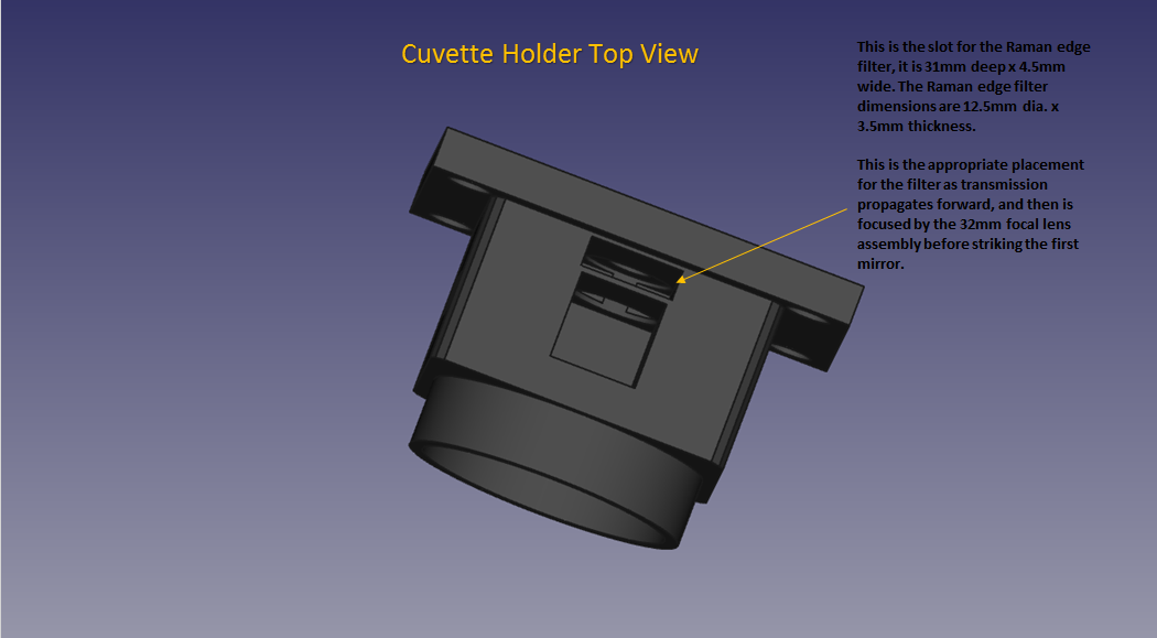
Added Filter Slot to Cuvette Holder (DAV5 V3 Spectrometer)
02/02/2017 at 14:01 • 0 commentsI designed the slot on top so the filter slips down and has a good fit, it does not need to be removed, even for absorption spectra, I may design a filter holder in the future in which you can place the filter in it and insert the whole assembly down the slot for easier removal.
![]()
![]()
![]()
-
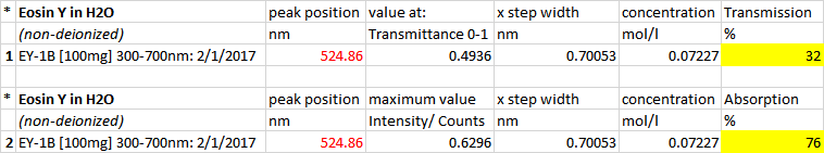
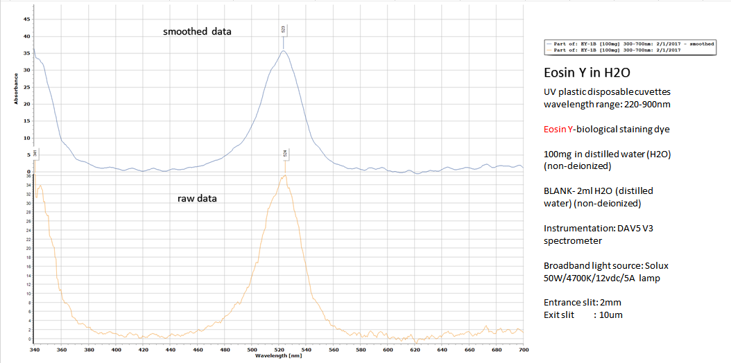
Absorption Spectra For Eosin Y in Water
02/01/2017 at 14:57 • 0 commentsWith some adjustments to the mirror and holographic grating, I have a much cleaner and higher signal to noise ratio than I was receiving before so here are the results for my absorption spectra of Eosin y in water:
![]()
![]()
![]()
This is the reference data from Leica microsystems, absorption and emission:
![]()
-
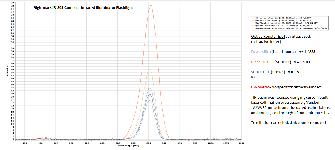
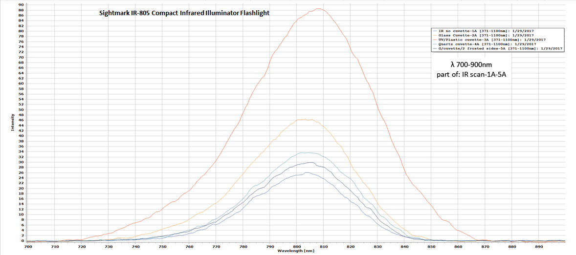
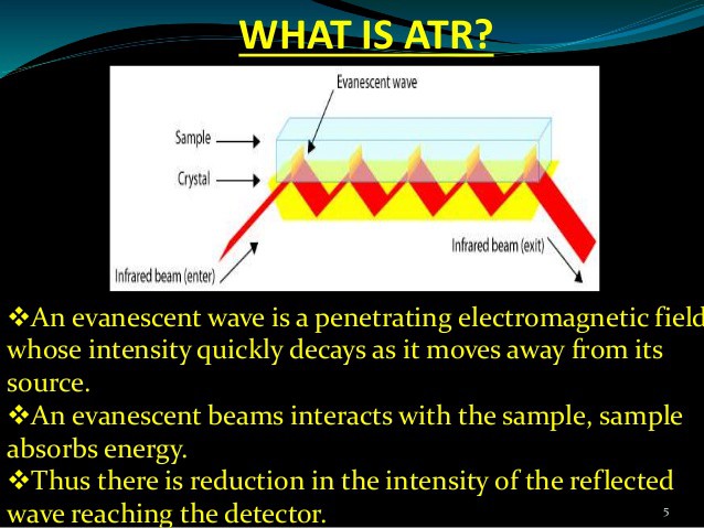
Experimenting in The TeraHertz Zone...
01/30/2017 at 17:32 • 4 commentsI wanted to do some experimenting with an IR flashlight of mine to see if in the future, I may be able to adapt it for ATR (.) Why ATR? ATR generally allows little or no sample preparation, which greatly speeds sample analysis. It allows very thin sampling pathlength and depth of penetration of the IR beam into the sample. Useful for samples that are too thick to be analysed by transmission and those that strongly absorb radiation.
![]()
![]()
![]()
![]() Reference;
Reference;http://www.slideshare.net/samikshasawant146/attenuated-total-reflectance-spectroscopy
-
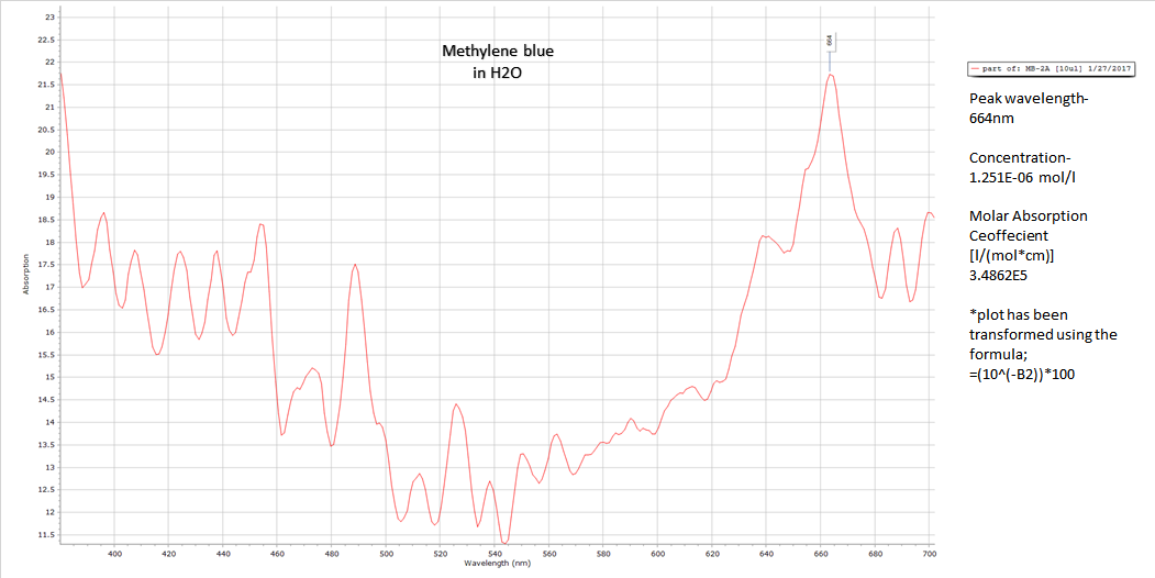
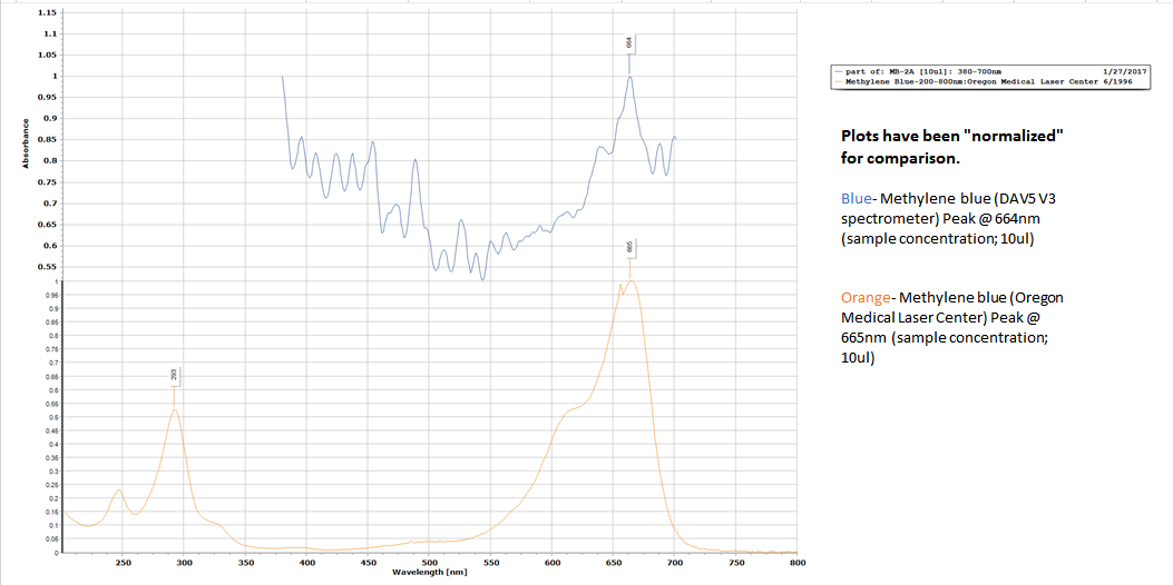
Absorption Spectra of Methylene Blue in Water
01/28/2017 at 15:01 • 3 commentsI tested the current absorption capabilities of this spectrometer and its resolution and I am definitely pleased with the results so far. There is still a lot of tweaking and adjustments to be made but those issues will be mostly resolved when I get the new 1800 ln/mm diffractive grating (Holographic) and the Raman edge filter.
This is a great start though, these plots represent a comparison between my spectrometer and the SpexFluoroMax ll used by the Oregon Medical Laser Center back in 1995-96. My sample of Methylene blue is the same as the one they used (concentration of 10ul) in a quartz cuvette in distilled water.Although their light source is superior to mine because of its stability, my Solux 50W 4700k isn't too bad (using a regulated 12vdc 5A power supply)
![]()
![]()
![]()
-
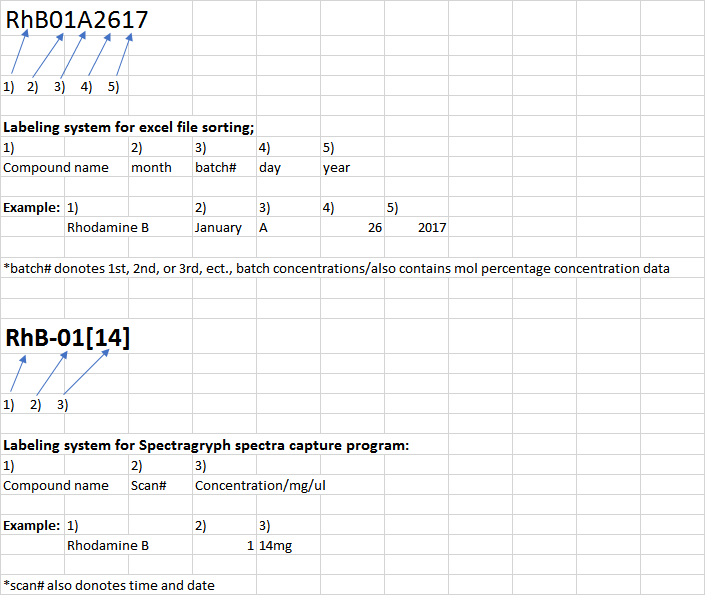
New Labeling System for Lab Work/2017
01/27/2017 at 15:12 • 0 commentsThis will be my new labeling system for 2017, this way I keep all data highly organized and can easily find and sort it...trying to keep everything professional :)
![]()
-
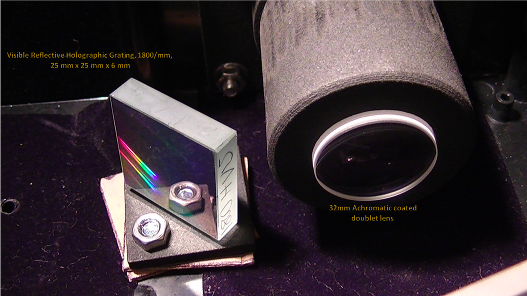
1000 ln/mm Holographic Diffraction Grating Sheet Results...
01/25/2017 at 10:42 • 4 commentsThis is the temporary diffraction grating that I have set up as a replacement for the DVD piece. Even at 1000 ln/mm I really didn't think it would work but I was wrong, it works beautifully! So...next month I will have my second mirror (concave focusing mirror) and my 1800 ln/mm Holographic diffraction grating for the Czerny-Turner configuration.
No more DVD piece...it's time has expired...
![]()
![]()
![]()
-
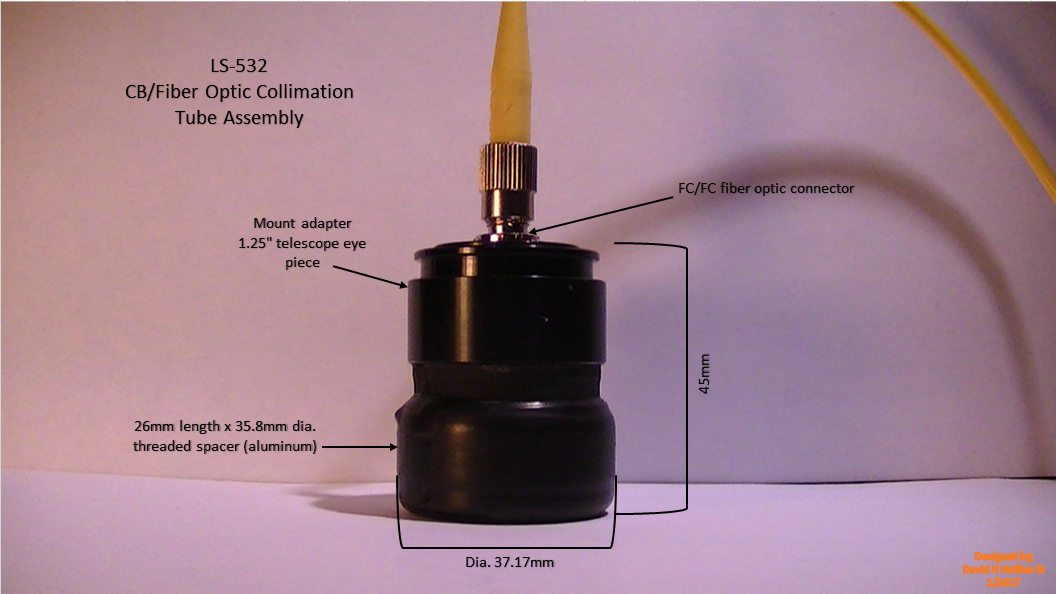
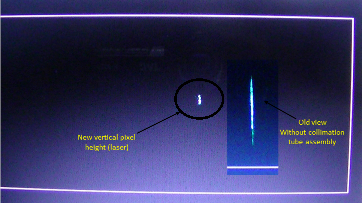
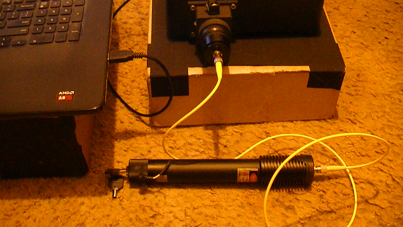
The LS-532 CB/fiber optic Laser Collimation Tube Assembly
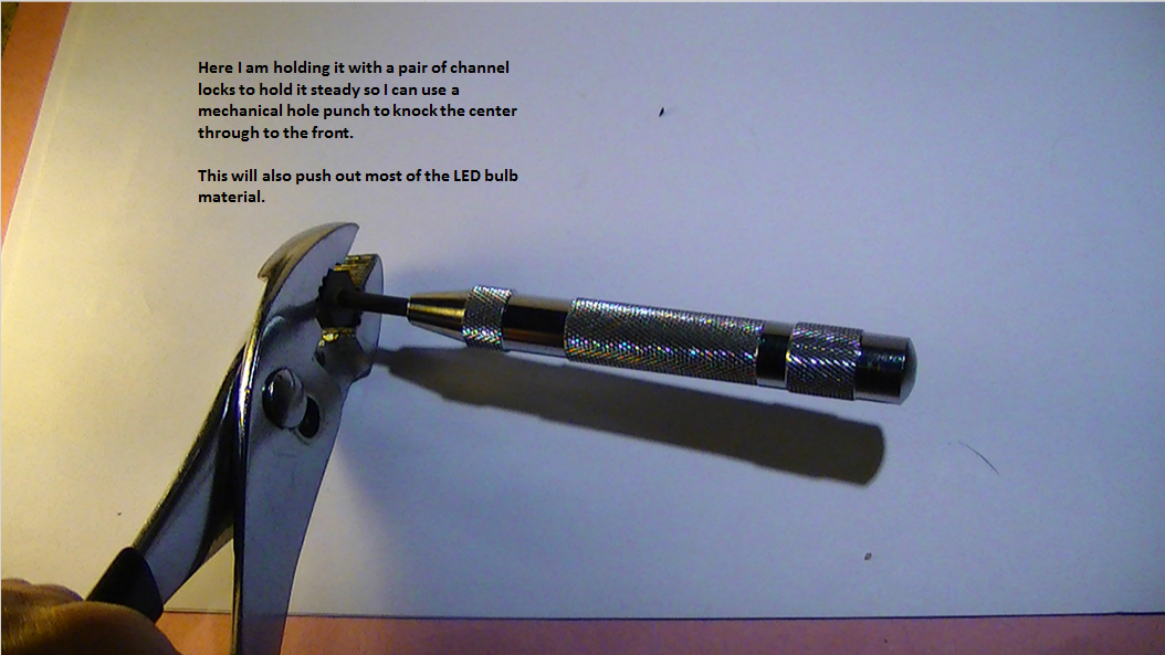
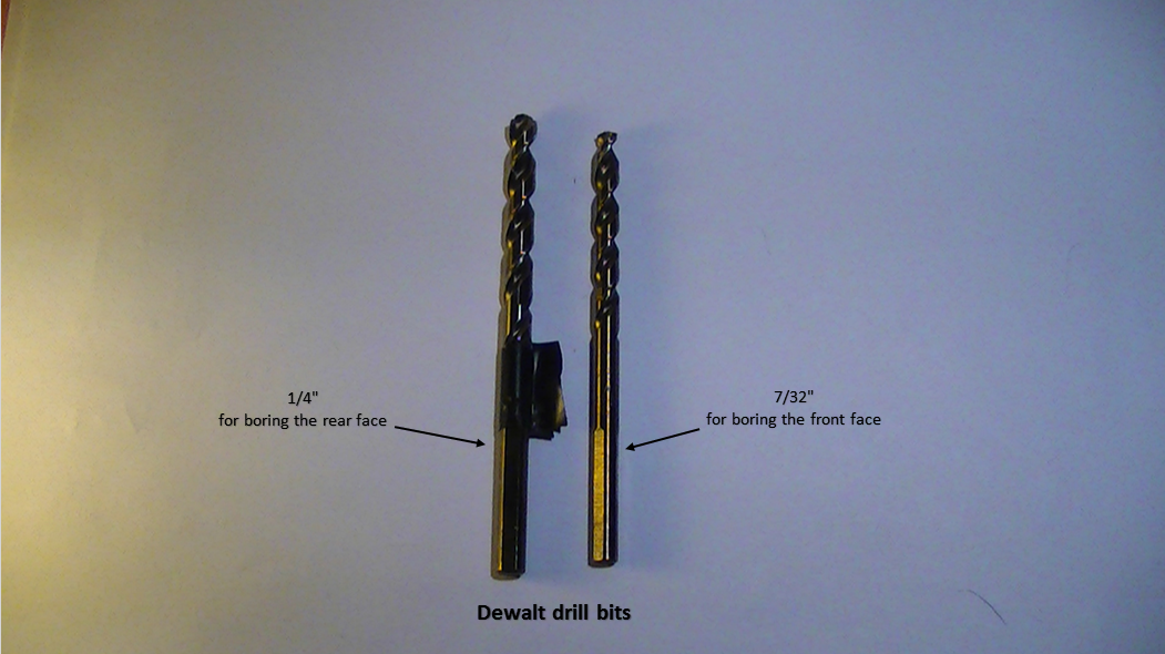
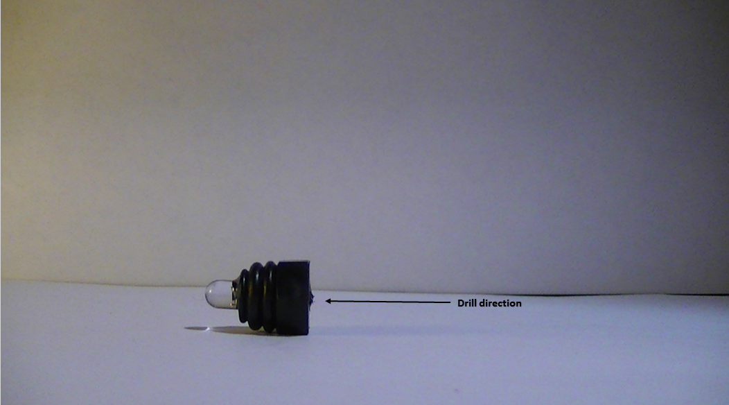
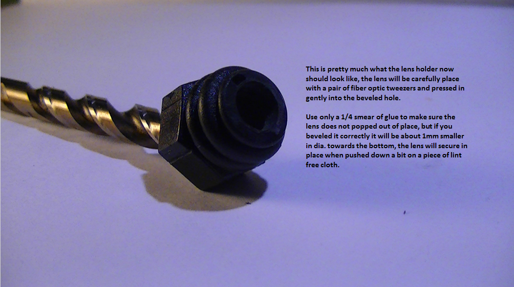
01/22/2017 at 11:55 • 0 commentsThese are the build instructions for my LS-532 CB/fiber optic laser collimation tube (at least this is what I call it);
![]()
![]()
![]()
![]()
![]()
![]()
![]()
![]()
![]()
![]()
![]()
![]()
-
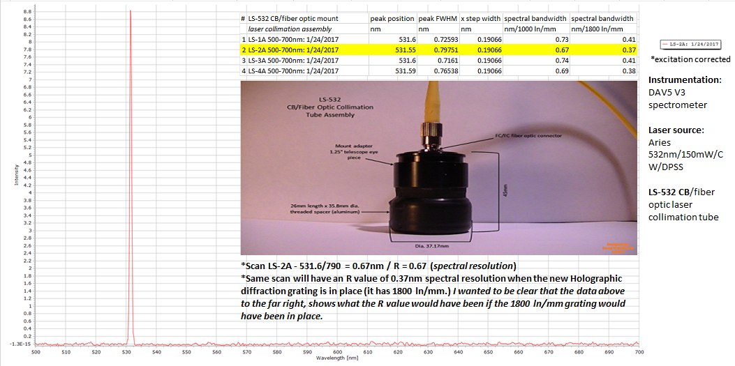
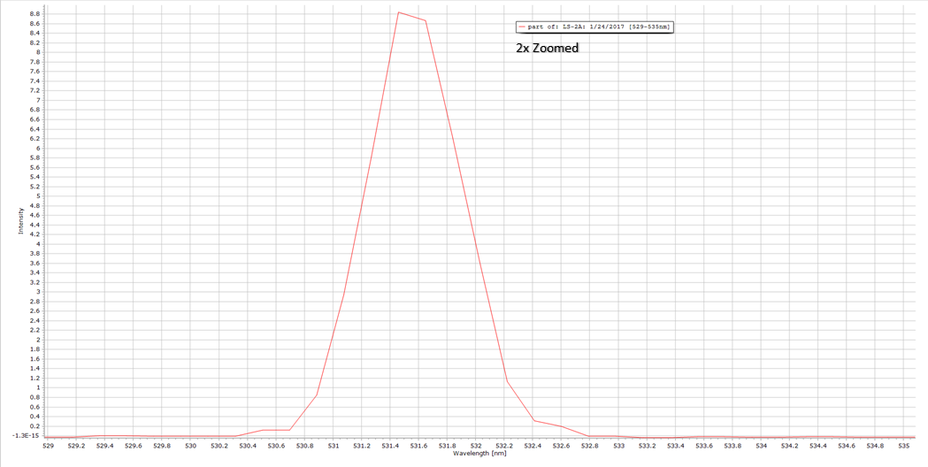
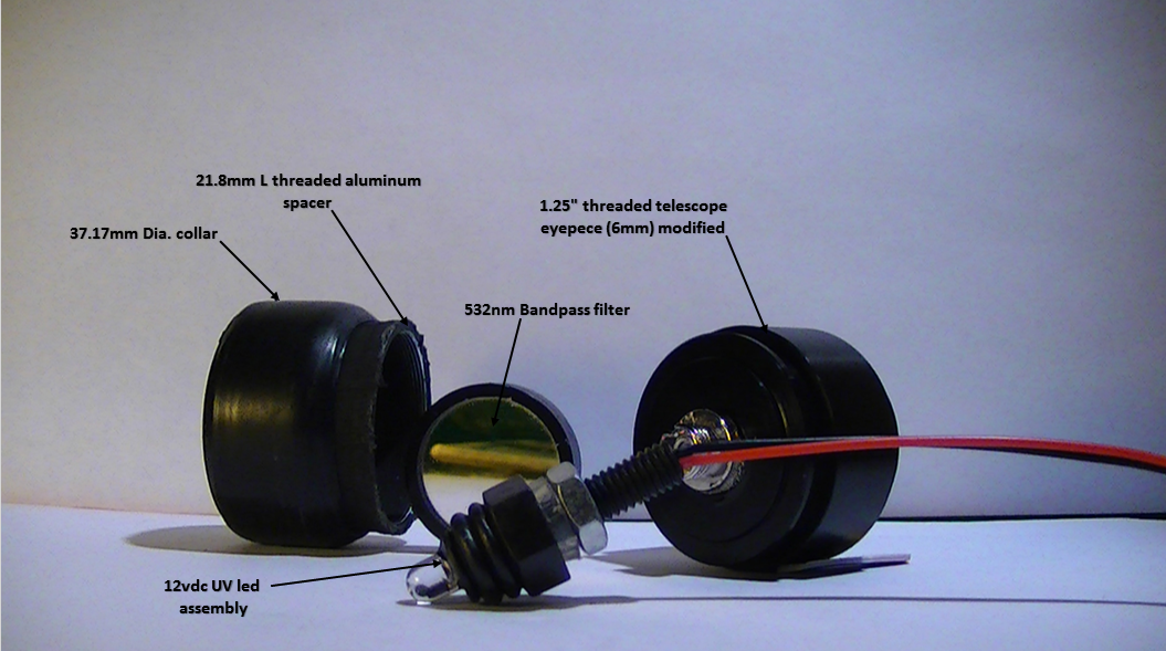
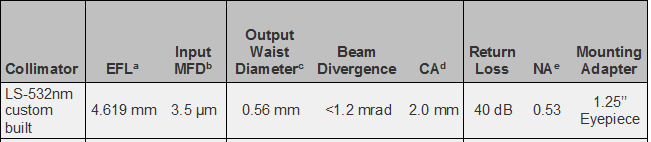
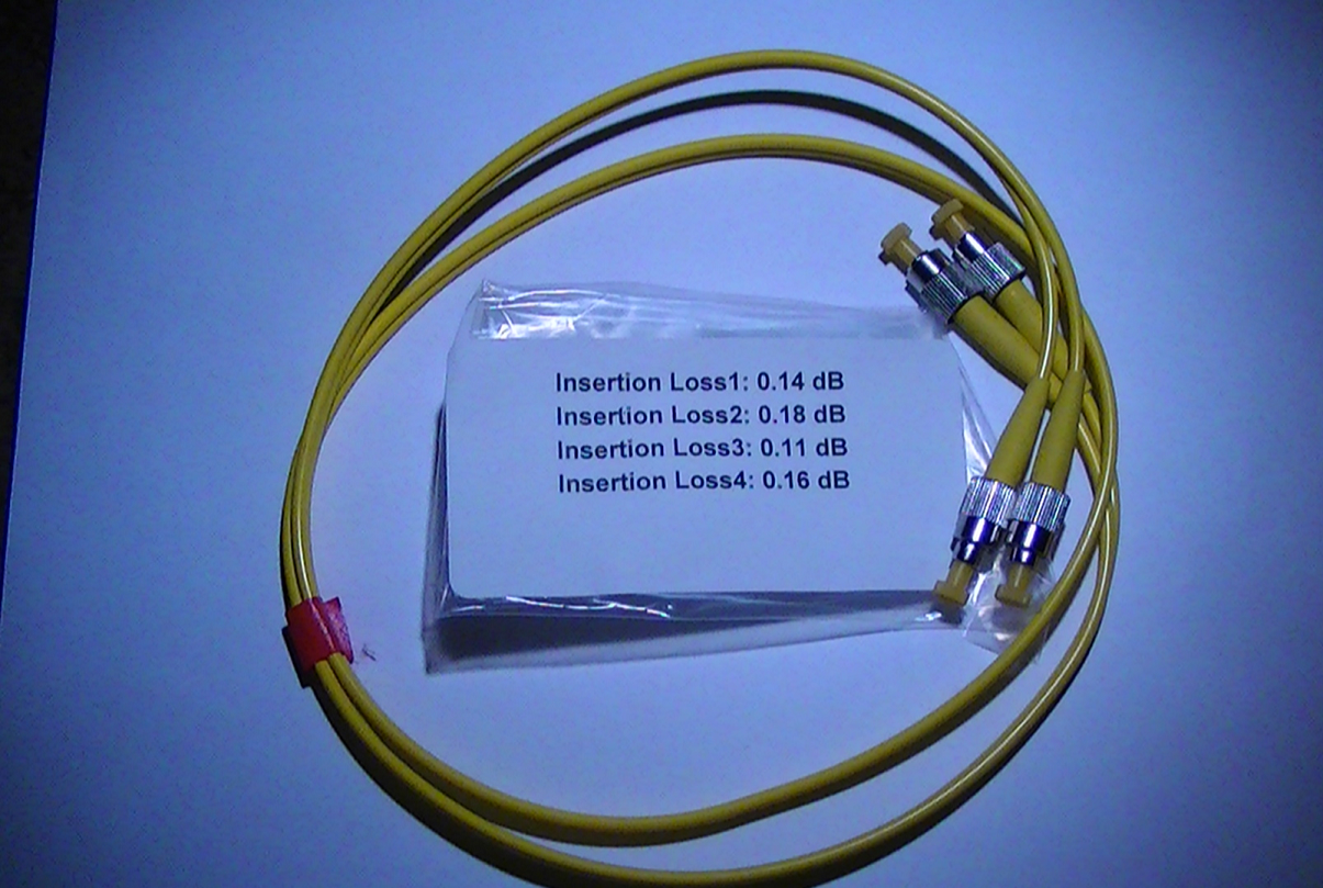
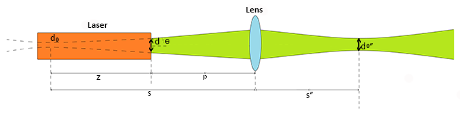
Final Design Stage - Fiber Optic Collimation Tube Assembly
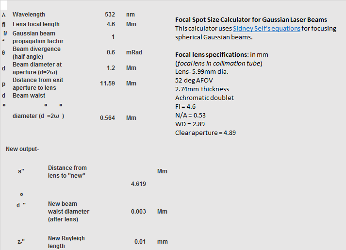
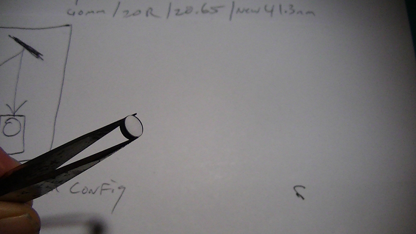
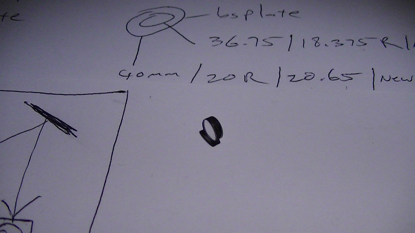
01/21/2017 at 13:52 • 2 commentsHere it is, my final design for the fiber optic collimation tube (laser.) I have thoroughly tested it and it works very well and here are all the documentation and specifications;
![]()
![]()
![]()
![]()
![]()
![]()
![]()
![]()
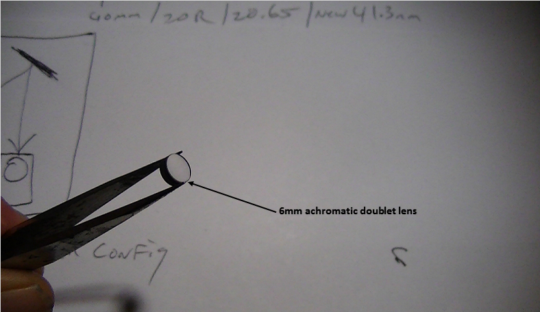
Lens used in collimation assembly- achromatic doublet
![]()
![]()
![]()
DAV5 V3.01 Raman Spectrometer
The only thing worth doing, is the thing worth doing right!