Justin Skists
-
The challenging ending...
10/30/2021 at 17:56 • 0 commentsOctober 31st
It's the end of a beautiful challenge...
I knew early on in the #RetroChallege that I had bitten off more than I could chew, and then I couldn't devote as much time to the project as I would've liked.
State of play
I had mentioned on Twitter, a couple of days that it felt like when you know the university assessment project deadline is looming but it's only half done, and the bits that are done aren't working at all...
![]()
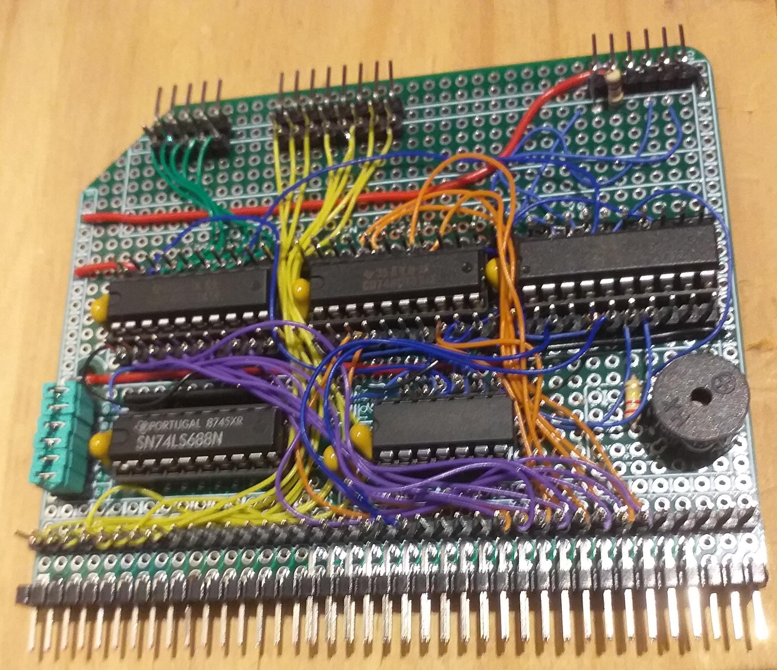
MIllRACE I/O Module
Build
Yes, it was built. :-)
![]()
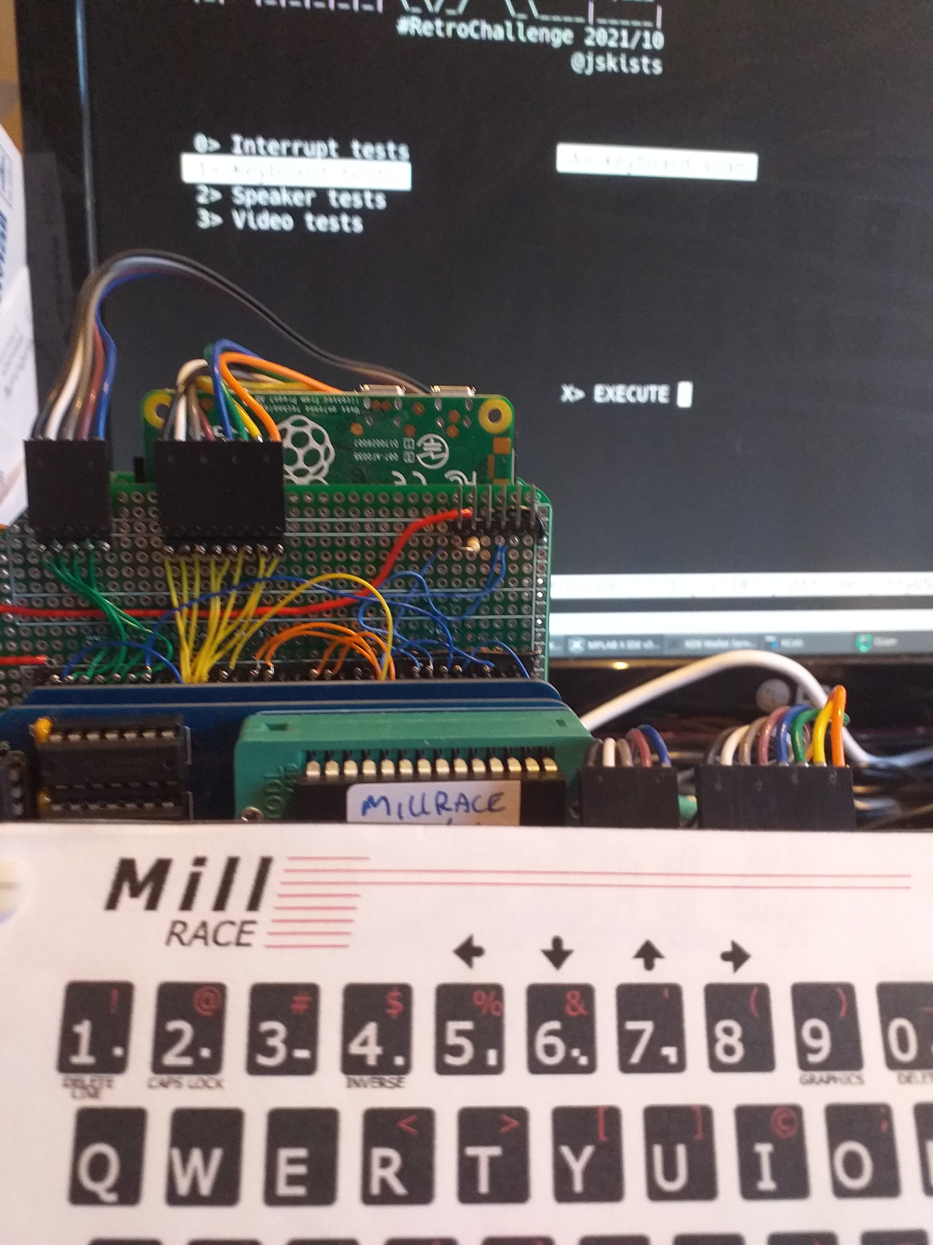
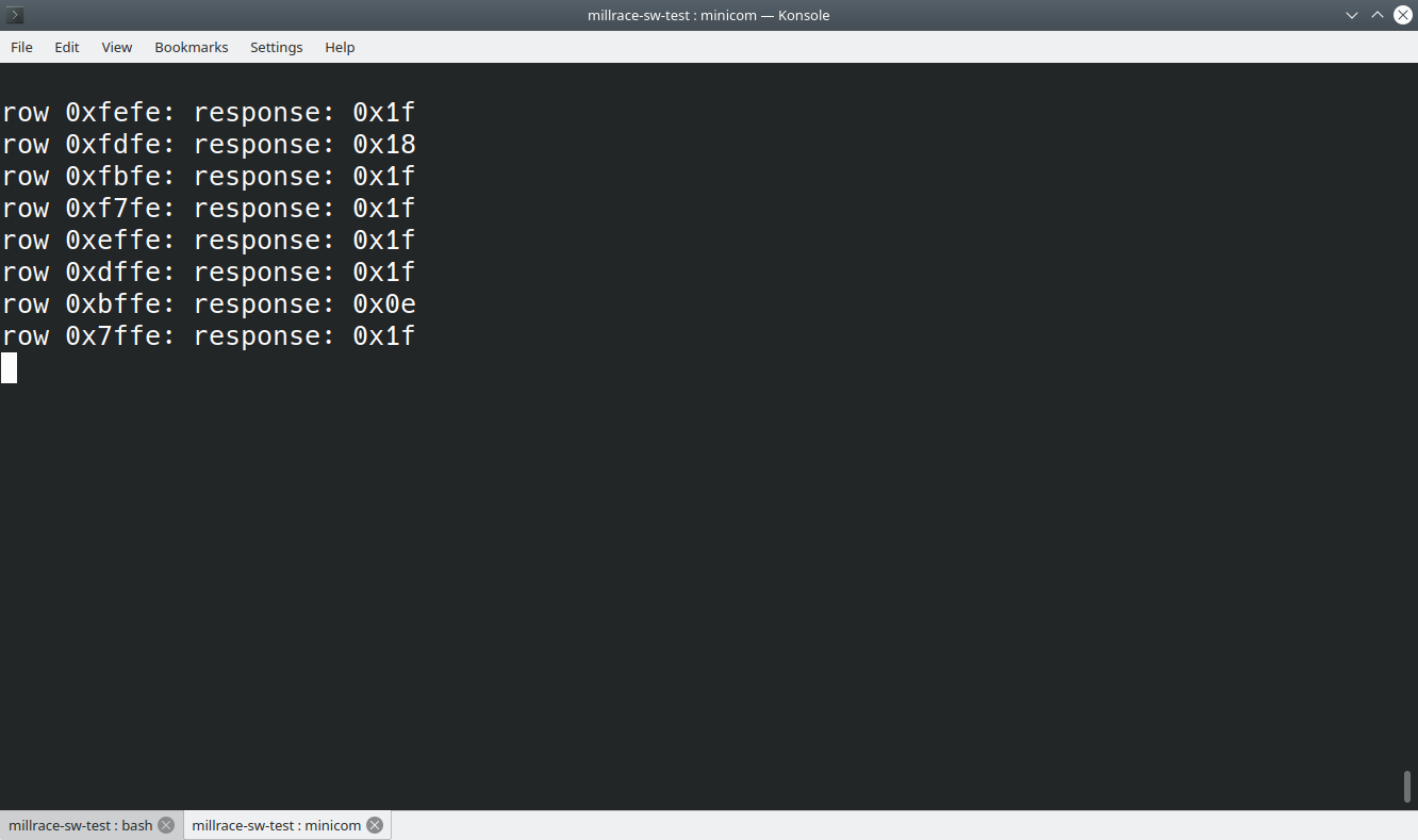
Keyboard
My test software was showing near-random output for scanning the keys, but you can see the values changing when a key is pressed. Plus, it looked a lot better when I reduced the RC2014 clock speed to 3.6MHz.
![]()
I've come to the conclusion that there needs to be a buffer between the Z80's address lines and the keyboard. It was suggested to use a latch, to eliminate timing issues, but that would negate the challange of using the "unmodified" Jupiter ACE ROM. There is room on the prototype board for another 74LS245. If I redesigned the board, I probably would utilise the WAIT signal for a few more clock cycles to get stable keyboard data.
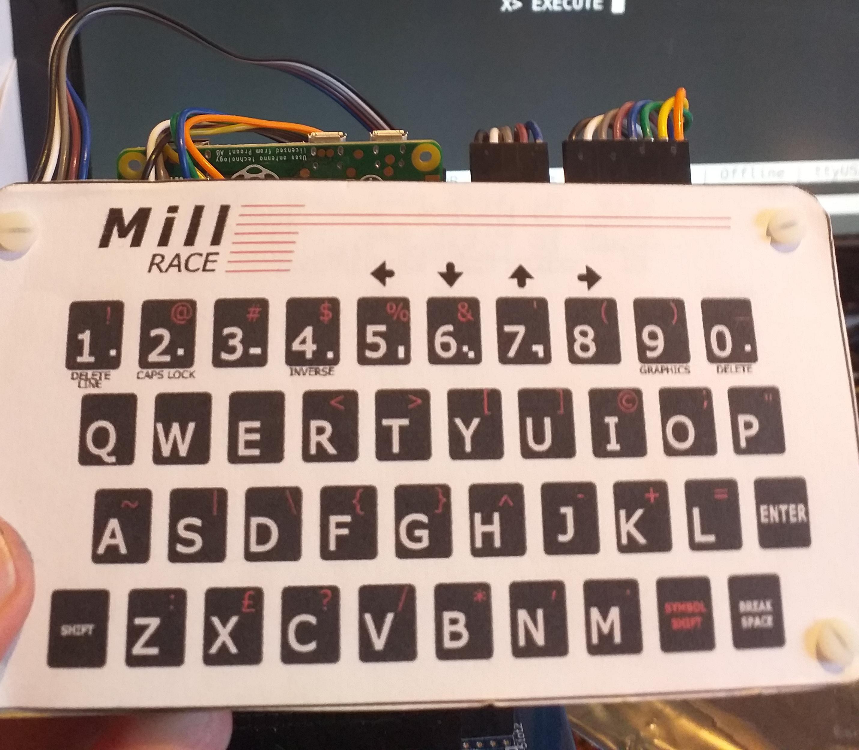
I really do like the look of my keyboard. It's effectively a paper overlay (I haven't laminated it yet) on top of the RC2014 Universal Keyboard.
![]()
Speaker
Due to the problems I had with the prototype board, I didn't get the chance to rewire the decoded IORD and IORW signals to the CLC pins of the PIC microchip.
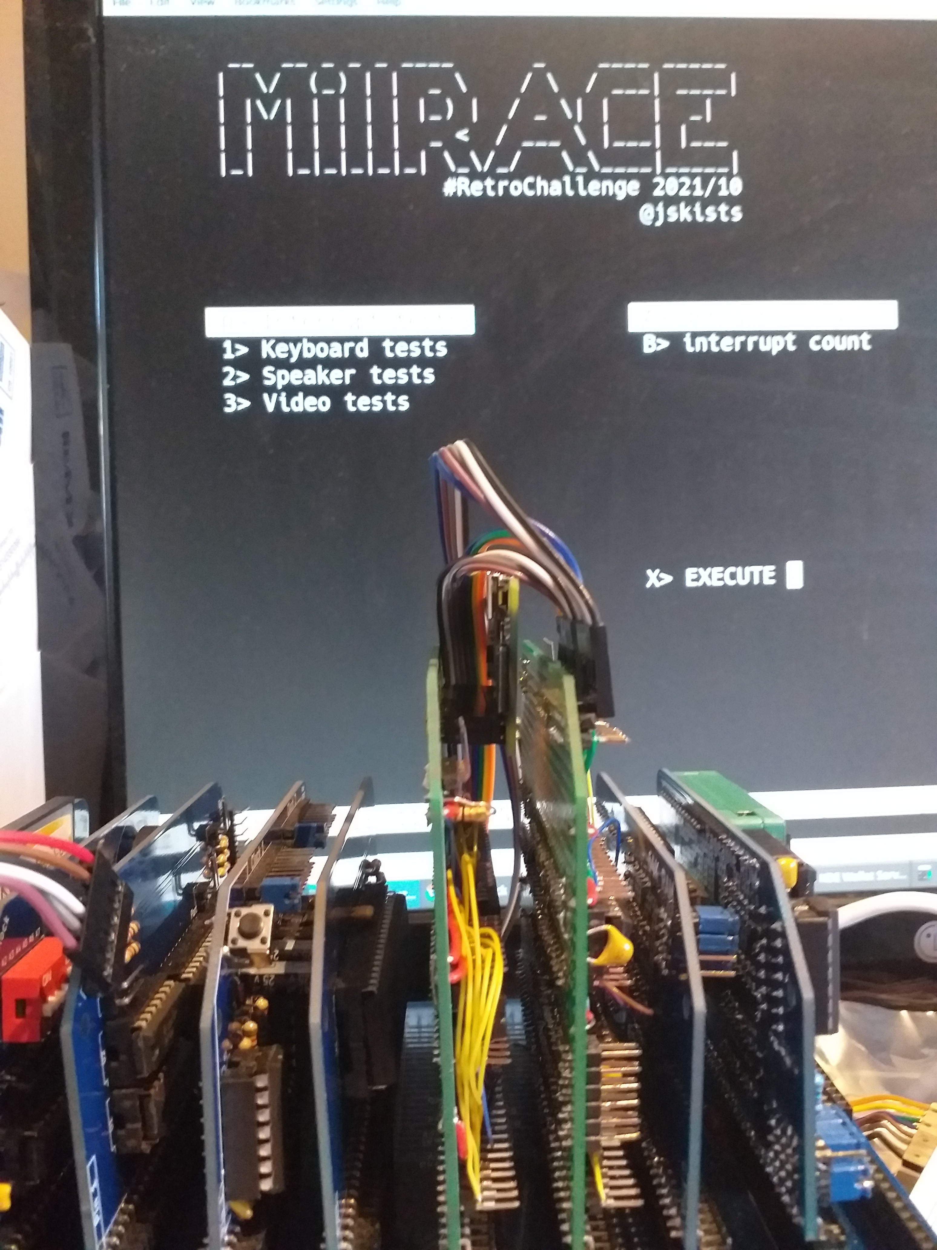
Interrupts
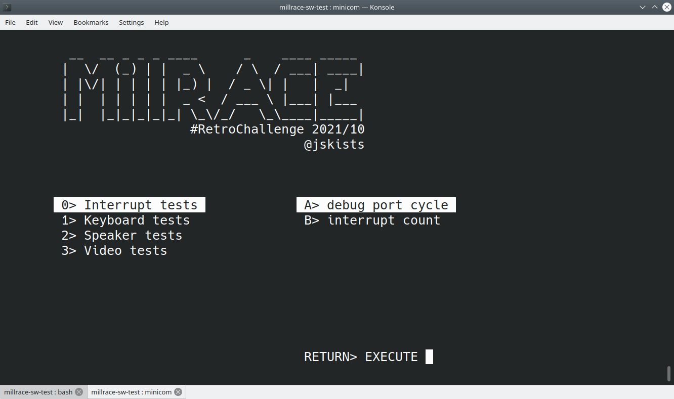
Yes, I was definitely generating interrupts. The firmware on the ROMWBW was definitely complaining about unhandle interrupts. This was why I decided to use my own ROM firmware to test.
![]()
And no, I didn't get around to implementing the interrupt tests. Using the "+rc2014 -subtype=sio" target on Z88DK didn't allow for ease of adding your own interrupt handlers, so having to create my own "Interrupt Mode 2" handlers, whilst keeping SIO "UART" capabilities are on my backlog (even if I can't use "stdio").
Tape recorder EAR and MIC
No progress what so ever on that! The PIC on the IO module has pins ready to read and write. My aim is to read the EAR and MIC, and convert it to a hex dump to output through the UART. The board will have a 10-way IDC connector allowing the EAR, MIC, and a UART off-board.
MillRACE Video Module
Build
The wiring between the PIC and the Z80 Bus is complete (barring any rework needed), but that is pretty much about it. I didn't get the time to work on it more.
![]()
ToDo
Things still to be done:
- write the PIC firmware to read data from the system RAM.
- add level shifters between the PIC and the RPi Zero.
- add SPI reading code to my video rendering software to control the PIC
Summary
![]()
This RetroChallenge project had been a blast!
Yes, nothing works -- yet -- but it's been a decent push in the right direction for my project. I probably wouldn't have even reached this stage, if I didn't participate in the challenge.
I've already got the itch to extend the Video module to support ZX Spectrum and other graphics modes...and maybe utilise the WiFi in the RPi to be a kind of DMA WiFi MODEM.
I have learned a great deal. I have also learned that I've still got a great deal more to learn!
So, will I continue this project beyond the challenge deadline?
A whole-hearted yes!
-
Build progressing...
10/30/2021 at 11:17 • 0 commentsDevelopment Boards
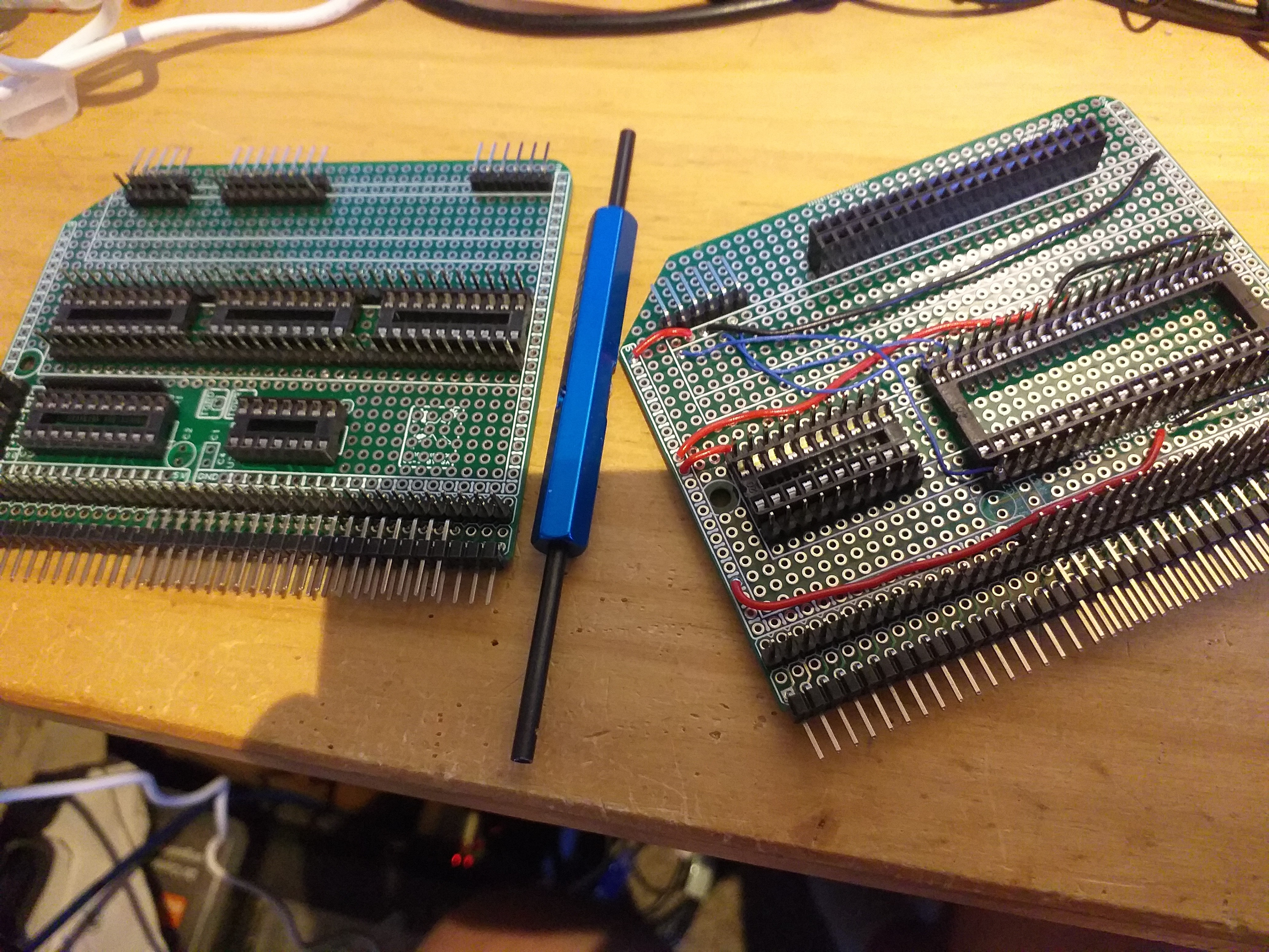
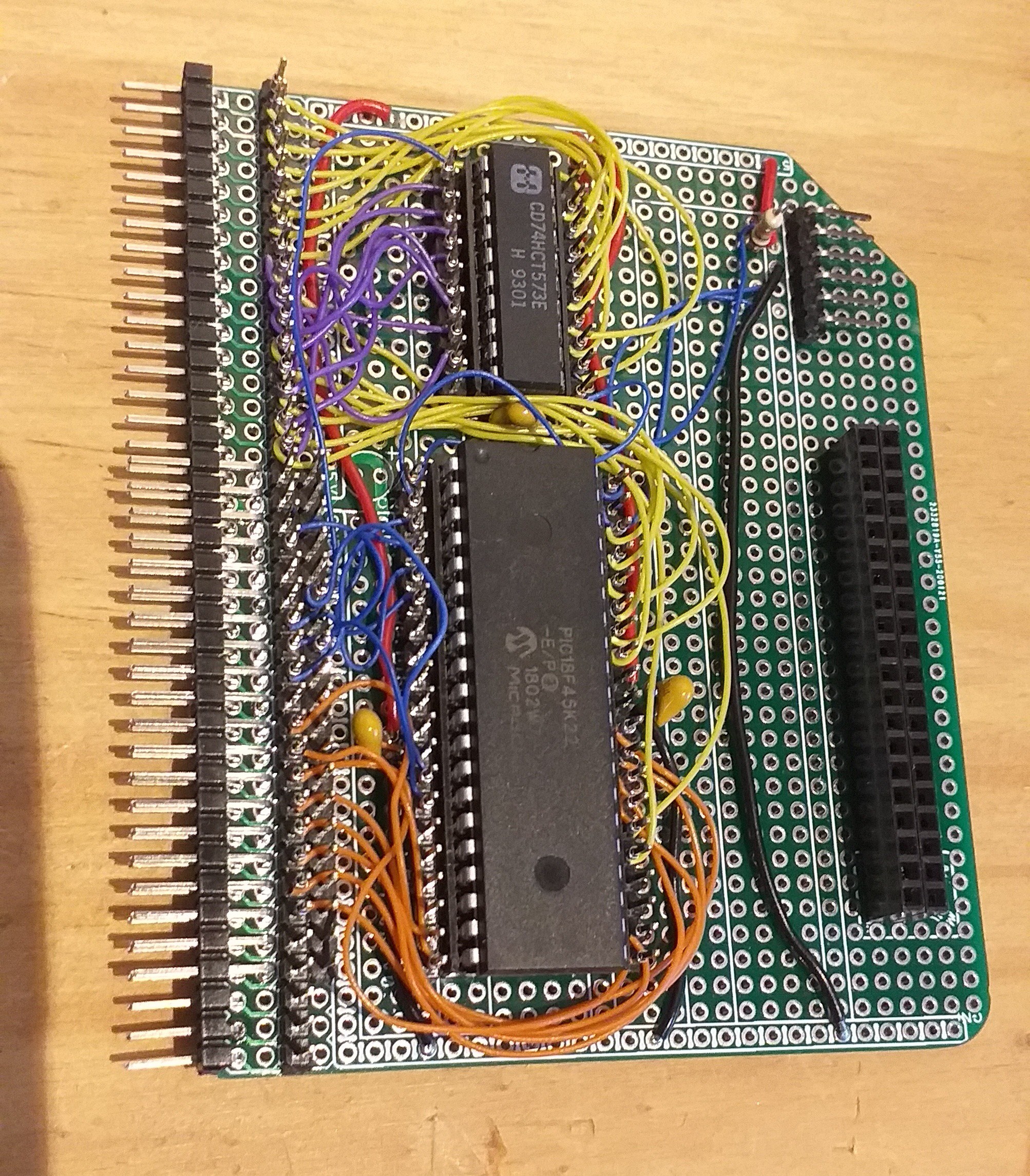
For my builds, I'm using two different RC2014 based prototype boards. Both are from DTRONIXS on Tindie.
This one for the I/O module, as it has built in address decoding, and this one for the Video module as it is intending to be a bus-master in its use.
For these boards, I'll be doing putting it together using wire-wrapping.
![]()
What's that?
Yes, wire-wrapping. In this case, I'm using strips of headers on top of the board
There are many reasons for choosing wire-wrapping techniques:
- It's easier to rework, allowing me to build and design incrementally.
- I don't have a fully child-proof workshop, so it's nice to be able to solder on the sockets and strips, quickly, whilst the chidren are out, and then wire it up at my leisure.
- And I've learned that it's quite therapeutic!
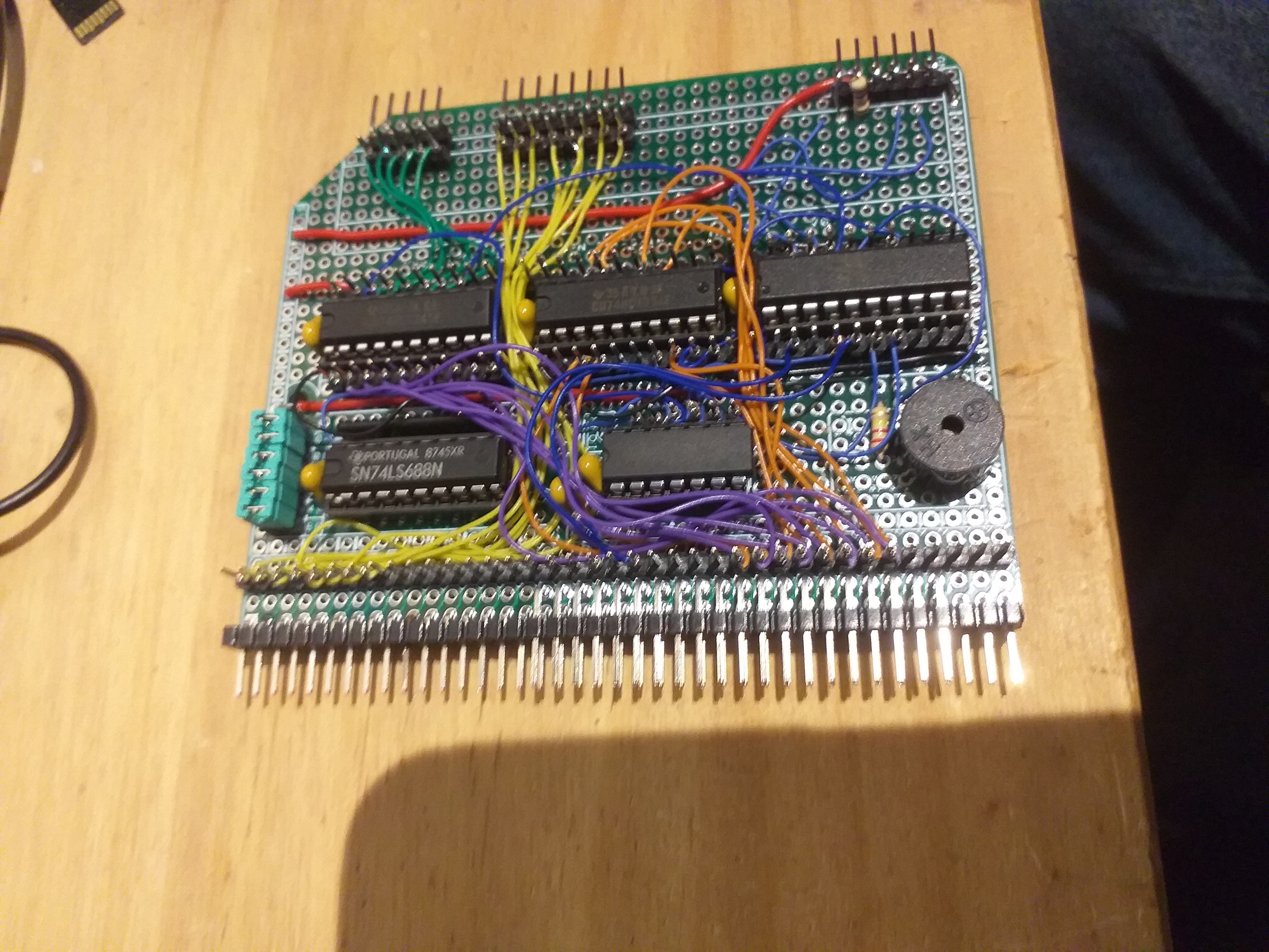
MillRACE I/O module
![]()
MillRACE Video module
![]()
-
Sound bites
10/30/2021 at 10:44 • 0 commentsHow does it work, again?
As I mentioned before, the Jupiter ACE exercised its beeping-speaker by reading and writing to the I/O port. Any write to the I/O port pushes the speaker diaphram out, and any read pulls it in.
The ZX Spectrum uses bit 4 of the I/O port to write to the beeper. So using ACE's technique, we can save a bit in the 8-bit output port, But, considering only one bit is used anyway, it's not much of a saving!
The downside of ACE's speaker circuitry, is that you'd presumably get an intermittent and random clicking sound during the operation.
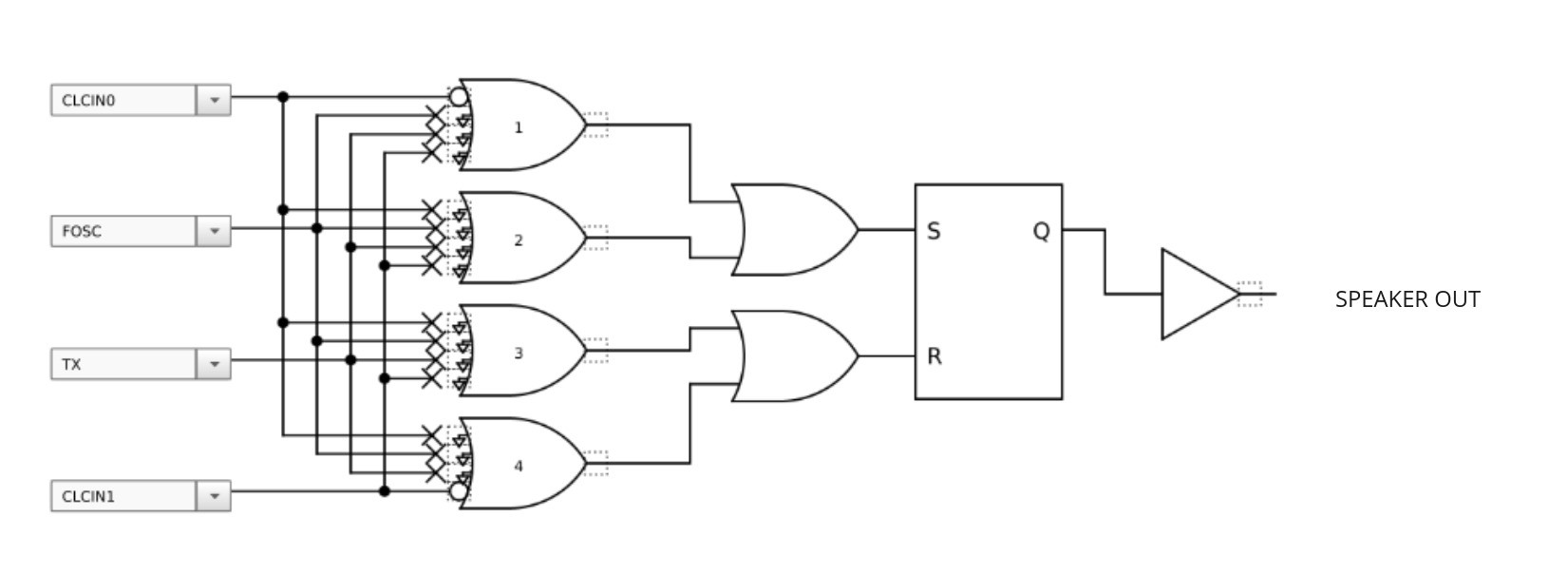
Implementation
Well, the original schematics of the Jupiter ACE uses a flip-flop to interface with the speaker. So, basically, a write to the I/O port sets the flip-flop, and a read resets it.
We could add a 74LS74 chip, and NOT the decoded RD and WR signals. But there is a different trick that we can use.
Microchip's PIC16F1509, that I've chosen for my design (because I had one lying around) has something known as a Configurable Logic Cell. It's a neat little peripheral that can combine other peripherals together, along with CPU control, to implement hardware-based protocols. For example, you could combine a signal with a 38KHz timer for infrared transmission.
CLCs are not as flexible as a CPLD, and they are restricted to which pins can be used, but they can have their uses.
And for our use, we'll just need to implement a flip-flip. Well, set up a CLC to use a flip-flop and invert the inputs.
Something like this:
![]()
-
Don't scream, it's the screen...
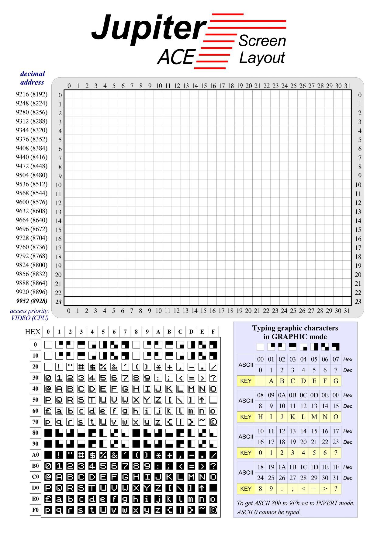
10/08/2021 at 17:14 • 0 commentsScreen layout
As we know, the jupiter ACE screen is a character based layout. Effectively, each character on the 32x24 layout is a pointer to the character RAM with pixel rows that define the graphic of the character.
![]()
An interesting thing to note, is that the Character RAM only has room for 128 characters. The highest bit (7) indicates whether the character is to be rendered in reverse video, or not.
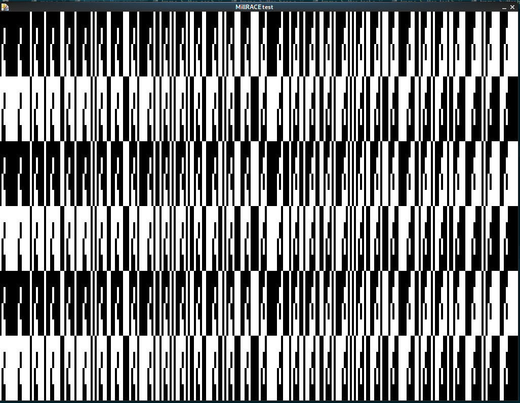
Test rendering
Here is an image of the software that will run on the Raspberry PI Zero, attached to the MillRACE Video module.
![]()
Each character is defined as a block of rows in incremental values from 0 to 0x7F. And the screen RAM is filled in a 0-0xFF cycle.
The rendering is the easy bit ... now I need to read the data from the real RAM!
-
Reading the screen memory
10/07/2021 at 18:22 • 0 commentsScreen memory
We know from a previous log that the screen is 768bytes @ 0x2400 and the character map is 1024bytes @ 0x2C00.
Hardware
The PIC will be acting as a bridge between the Raspberry PI (used to render the screen image to a HDMI viewing device) and the Z80 bus. The PI will command the PIC to read a portion of the Z80 memory space, and then provide it as a SPI byte-stream. Once the PI has collected the required data, it will render it its own framebuffer.
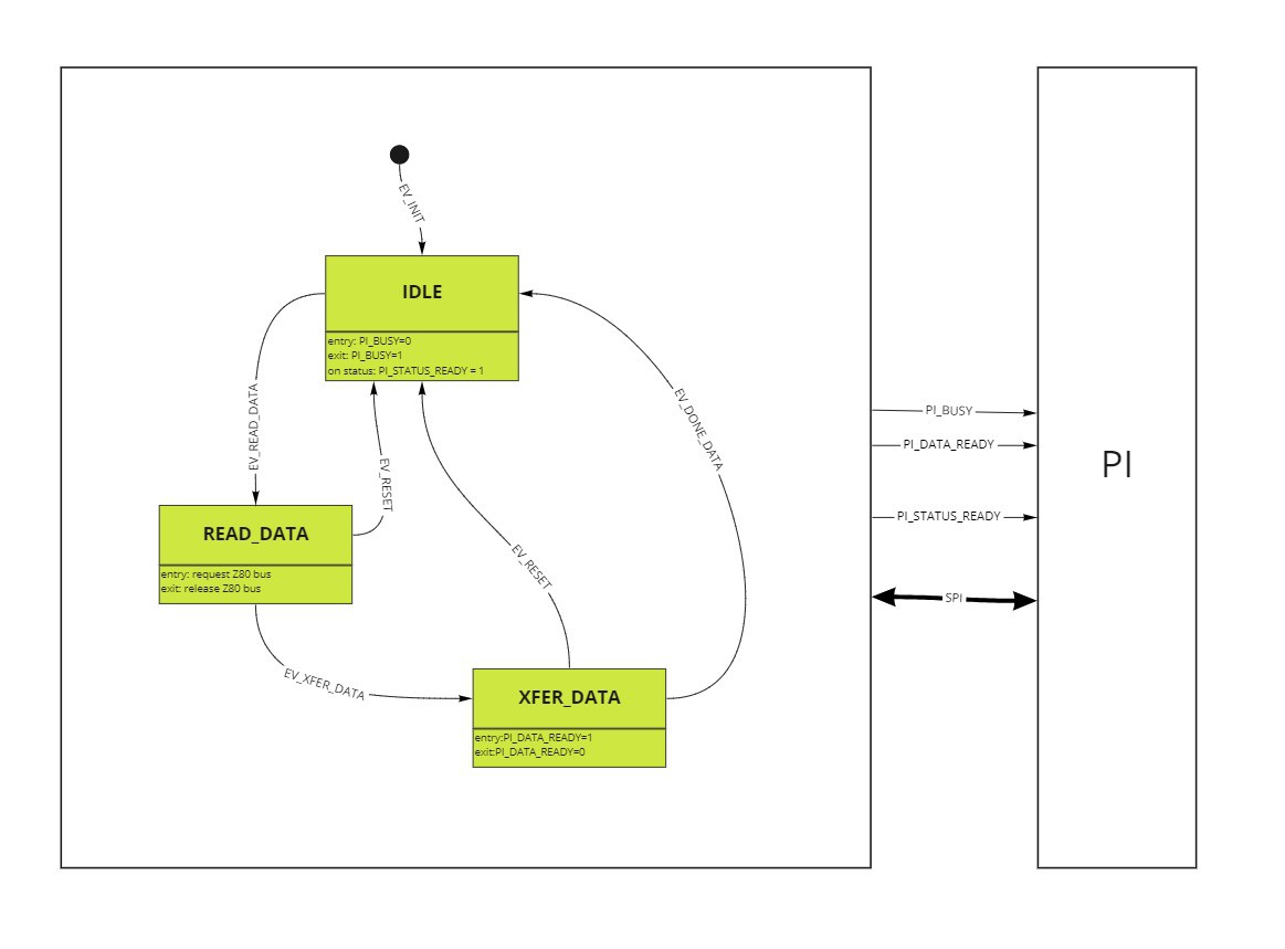
State machine
I love state-machines! Here is a draft of the PIC's:
![]()
Whilst the PIC is in IDLE state, it is prepared to receive commands from the PI over the SPI bus. One such command will be to fetch the "status" of the PIC, if one is signalled, and another is to request to read a block of memory.
In the READ_DATA state, PIC has requested control of the Z80 bus, and is currently reading the requested number of bytes from memory space.
Once all the data has been read from the Z80 bus, it goes into the XFER_DATA state. This is when the PI can read the collected bytes over the SPI.
Once the data has been transferred, the PIC goes back to the IDLE state.
The hardware
As an 8-bit PIC, there is no SPI FIFO, so the speed can not be very fast.
The PIC is perfectly happy with 3v3 as a "logic high". I plan to use a resistor-based voltage-divider for the PIC-to-PI signals....with the expected reduction speed of the SPI for the PIC to manage, I'm sure the voltage-divider will be fine. :)
-
Tick-tock, tick-tock...
10/06/2021 at 14:01 • 0 commentsFrame interrupt
The Jupiter ACE only had one interrupt source. It was a 50Hz (presumably, 60Hz in the USA) "frame" interrupt.
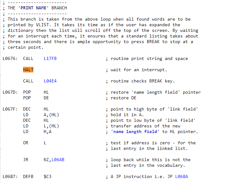
The Jupiter ACE ROM listing shows that the ROM uses the HALT instruction to slow down printing of VLIST.
![]()
The Reference manual has example of uing the HALT instruction to slow things down, too.
Implementation
We will use a timer on the PIC on the MillRACE IO module to generate the interrupt.
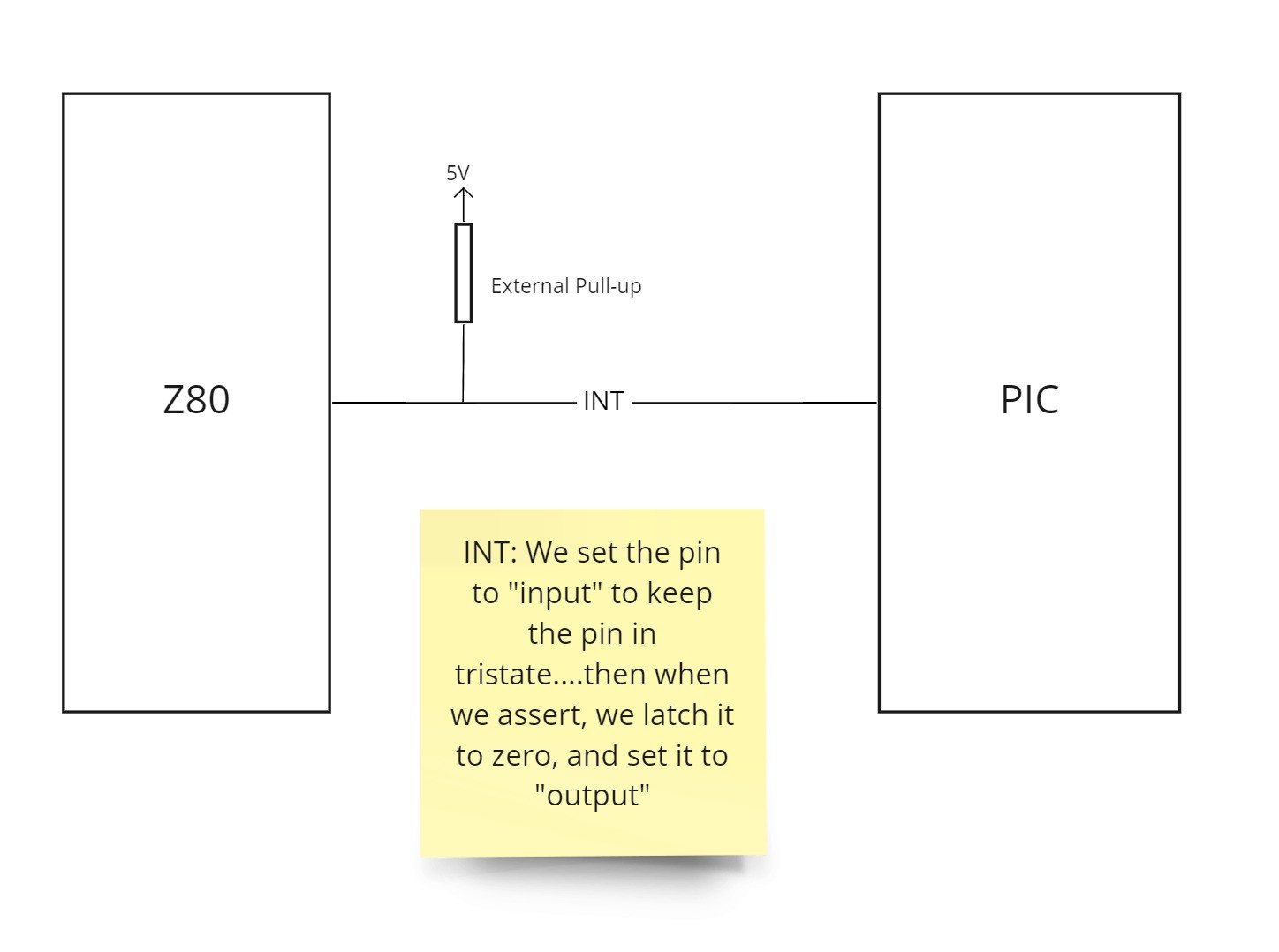
The RC2014 Z80 CPU module uses an external pull-up resistor to keep the interrupt line high. This would mean that, if we wanted to assert the interrupt-line, then an open-drain GPIO output should be used. However, the PIC we're using doesn't have open-drain pins.
So, to give the same behaviour, we'll do the following to pulse the interrupt line:
- set the pin to input
- latch a 0
- do
- when timer fires, switch pin to output (assert INT)
- wait a short time
- switch pin to input (de-assert INT)
- repeat
![]()
How long do we pulse the interrupt line for?
Rough maths: According to this page, we need pulse for at least 23 Z80 clock ticks. As the PIC (running at 16MHz) is running twice as fast as the Z80 (running at 7.3MHz), the PIC will need pulse the INT line at least 51 ((32*16)/7.3) PIC clock cycles. With each PIC NOP instruction taking 4 clock cycles, there will need to be at least 13 (51/4) NOPs between assertion and de-assertion....let's round it to 16.
The future?
If I were to make this a more general purpose module, I would normally like devices to own up to interrupt assertions. if this frame interrupt happened at the same time as, say, a serial interrupt, I would like to know that I need to do something with the frame interrupt.
So, what I would probably do, is program the PIC to place a 1, indicating that the "frame" interrupt has pulsed, on BIT[7] of the input port. This would then be cleared on a read or on a write of 0x80.
Yes, I'm thinking about stretch goals already....
-
Crazy Memory
10/03/2021 at 16:20 • 0 commentsMemory Map
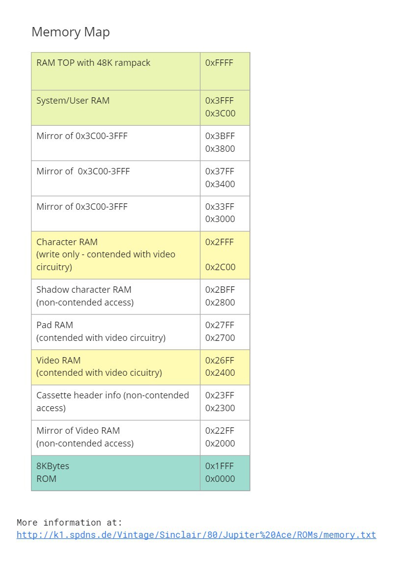
What can I say about the Jupiter memory map?
A basic Jupiter ACE memory map looks a little like this:
![]()
Yes, it's a little crazy, using a mixture of dual-port RAMs and a liberal requirement of address decoding...
According to this little document, the ROM only accesses the video memory using the 0x2400-0x26FF range.
This is a little "phew" moment, since I wasn't sure how to handle the mirrored memory using stock RC2014 memory boards. Without double checking, I'm really hoping the ROM does the same thing with the character RAM.
Obviously, some applications/demos are likely to optimise for performance and use the non-contended video access RAM locations, along with the mirrored memory spaces. However, as they say in the corporate world, when greeted with a challenging, but not-specifically-written-down use-cases: "It's not in the requirements!"
My requirements are to get the Jupiter ACE ROM running on the RC2014.
Therefore, I think, for the ROM, the video module should be OK with reading 0x2400-0x26FF for the video RAM, and 0x2C00-0x2FFF for the character RAM.
-
IO Ports
10/02/2021 at 16:59 • 0 commentsIN, OUT, IN, OUT, shake it all about!
According to this IO document, there is only one official Z80 port used, at 0xFE. Actually, if you look at the schematics, only ADDRESS[0] is decoded...so, any even address would trigger it!
Output
On an OUT instruction to to 0xFE, only BIT[3] is really used; the MIC. This, assumably, would send high/low signals to the tape recorder to save files.
Input
The input of port 0xFE is a little more interesting:
![]()
BIT[5] is the current level of the incoming tape signal for loading from the tape.
BIT[4:0] is a sampling of the keyboard matrix. The current row is selected using the Z80 ADDRESS[15:8] during the IN instruction read.
There is plenty of spare bits in the port for future use. For example, the ZX Spectrum uses BIT[4] on the output for speaker control, and BIT[2:0] for border colour...
Speaker
So, what about the speaker? The Jupiter ACE had a speaker, and it needs to be controlled. Shouldn't there be a BIT in the 0xFE port assigned to it?
Well, looking at the schematics, there is a flip-flop used in the speaker. Why? Well, think about how a speaker diaphram works, to make sound: in, out, in, out, in, out...
Looking at the schematics, any write to 0xFE pushes the speaker's diaphragm out, and any read from 0xFE pulls the diaphragm in. IN, OUT, IN, OUT....
The Jupiter ACE ROM listing seems to confirm it, with the BEEP word.
![]()
-
Initial thoughts...
09/12/2021 at 16:49 • 0 commentsOverall
In this project, I am not going for full Jupiter ACE compatibility. I'd like to work toward it, but there is no way I'l be able to complete it by the end of October. My challenge is to run the official ROM, not every single demo! :)
My initial thoughts are to take a standard RC2014 with the following items, and add my new "challenge" modules:
- Enhanced backplane
- Z80 Module
- Dual clock module (currently at 7.3MHz, with option to support external clock for the Jupiter ACE frequency)
- Pageable ROM module (flashed with Jupiter ACE ROM image)
- Pageable RAM module
The Interface Module
The Jupiter ACE had very simple I/O. Basically, everything on-board was accessed by a single Z80 I/O port: 0xFE. (To be honest, looking at the schematics, it's actually accessable by every odd-numbered port address! But, officially, it's 0xFE)
This port gave access to:
- the keyboard
- the speaker
- the EAR socket (for tape loading)
- the MIC socket (for tape saving)
This is what I'm thinking of:
![]()
I originally choose the PIC18F4520, as it has the "parallel slave port", for microprocessor interfacing. Handy!
However, I didn't beleive the microcontroller could read the "keyboard", to place the value into the port, quick enough before the Z80 finished its read-cycle. So, I would need to choose another microcontroller; probably PIC16F1509 or PIC18F26K22 (as I know that I have at least one of them lying around), and use a couple of 74LS' chips to implement the read and write port.
I'll probably not get tape saving/loading completed in this challenge, but I'm leaving it open for future development. The reason for using the PIC, is that it should be possible to process the tape audio and save it to EEPROM, output hex-file through a UART, or similar. Also, the PIC will provide the 50Hz frame interrupt.
Video module
The Jupiter ACE has a nice memory-mapped character-based monochrome video. It was implemented using TTL logic!
There is no way I'm going to be able to replicate it in the time given.
So, I'll be taking my inspiration from the BusRaider module. In this case, a PIC microcontroller will read the area of RAM, that hold the the Jupiter ACE's screen and character map, which will then be passed to the Raspberry PI (via SPI) to decode and display to screen.
![]()
My choice of the PIC18F46K22 is because it is a 40pin IC, plenty of pins to access the Z80 bus, and has enough RAM to read and store the area of memory read for Jupiter ACE, before passing it to the Raspberry PI.
Yes, using the Raspberry PI as a vdeo card is cheating, but there is precedent for its use in the RC2014 world. I'm not a hardware engineer, and I don't have the tools to create and debug a full-on TTL VGA/HDMI video interface, so I intend to push that problem into a domain I'm much more familiar with: software.
I'm fully aware that I won't get 50Hz frame rate using this setup. I'm just hoping for enough frames-per-second (FPS) to make it usable -- to be honest, I'd probably be happy with just 1 FPS, as long as I can see something!