 kwikius
-
1Get car reversing kit
Firstly you will need to get the £10 car reversing kit off ebay. The type you want has 4 ultrasound transducers. You don't need the ones with video cameras etc. Beware that the control circuit will need some modifications which will stop it working as a car reversing sensor, unless you take care to make the modifications reversible.
Please do understand that at this time, it requires removing some smd components from the board and soldering wires to small traces , so you will need some understanding and experience of electronics and testing and faultfinding of pcbs to be able to make this project.
Note that your PCB may not be exactly the same as the one here, but I believe the layout of these boards is basically similar, at least on the 2 I have.Firstly you need to make an extra piece of circuit board and add it to the existing PCB. Just after doing this video I discovered that the simplest way to join the extra board was with double sided tape, which is what I then did.
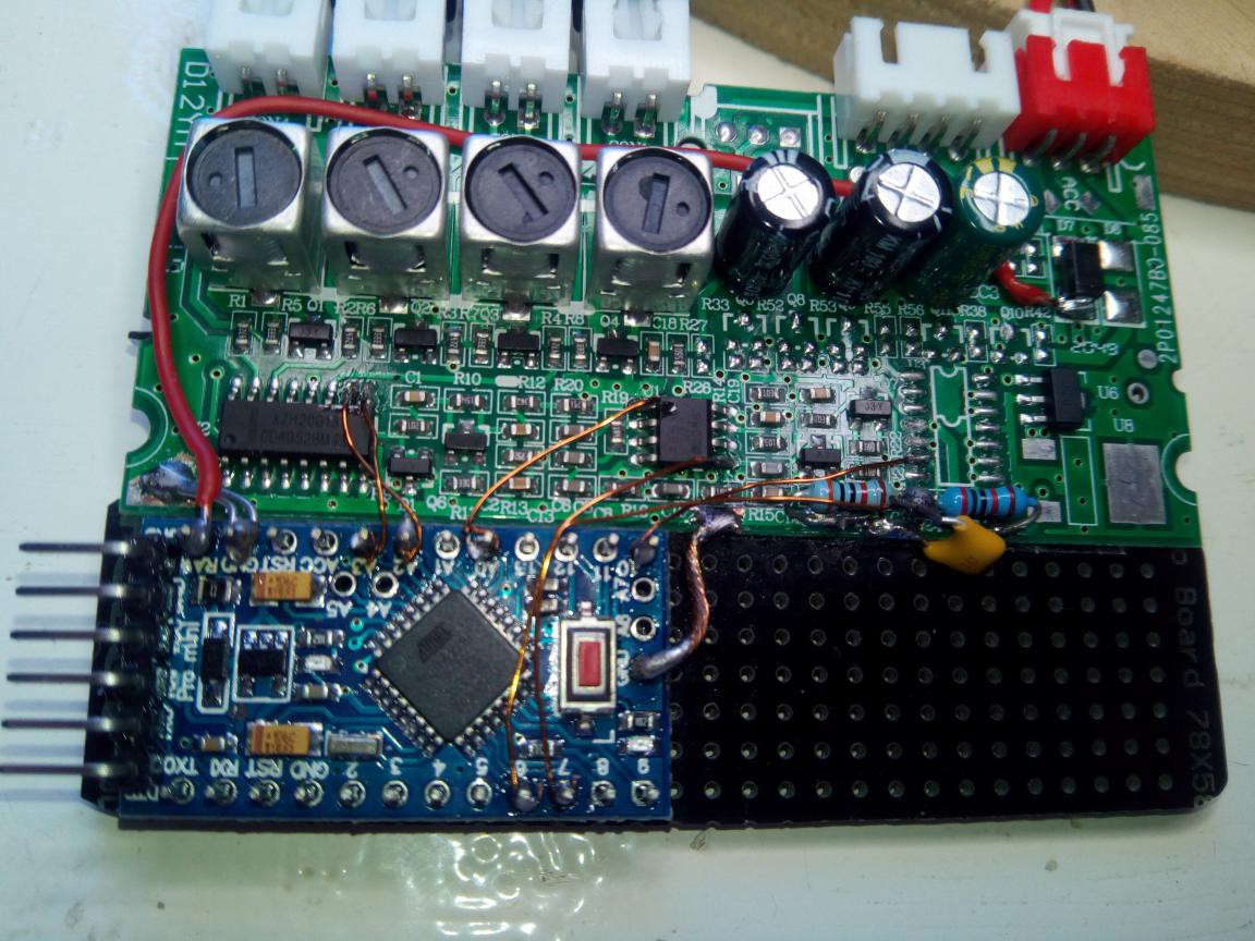
Next you will need to identify and remove the existing microntroller. On both boards this was an 8 pin SOIC chip (though on the second, in a footprint that could also take a 14 pin version), which I believe to be a PIC12. Beware that there is also an 8 pin soic dual op-amp ic on the pcb which is used for the band pass filter. The mcu is unmarked , while the op-amp is marked and surrounded by resistors and capacitors ( I have one marked as a 4558D and the other as a N5532 ) so if you have a marked ic, hopefully, you can look up what it is exactly to verify it is the dual op-amp
The Arduino can now be soldered in place on the PCB as shown in the photo. See also the later diagram.
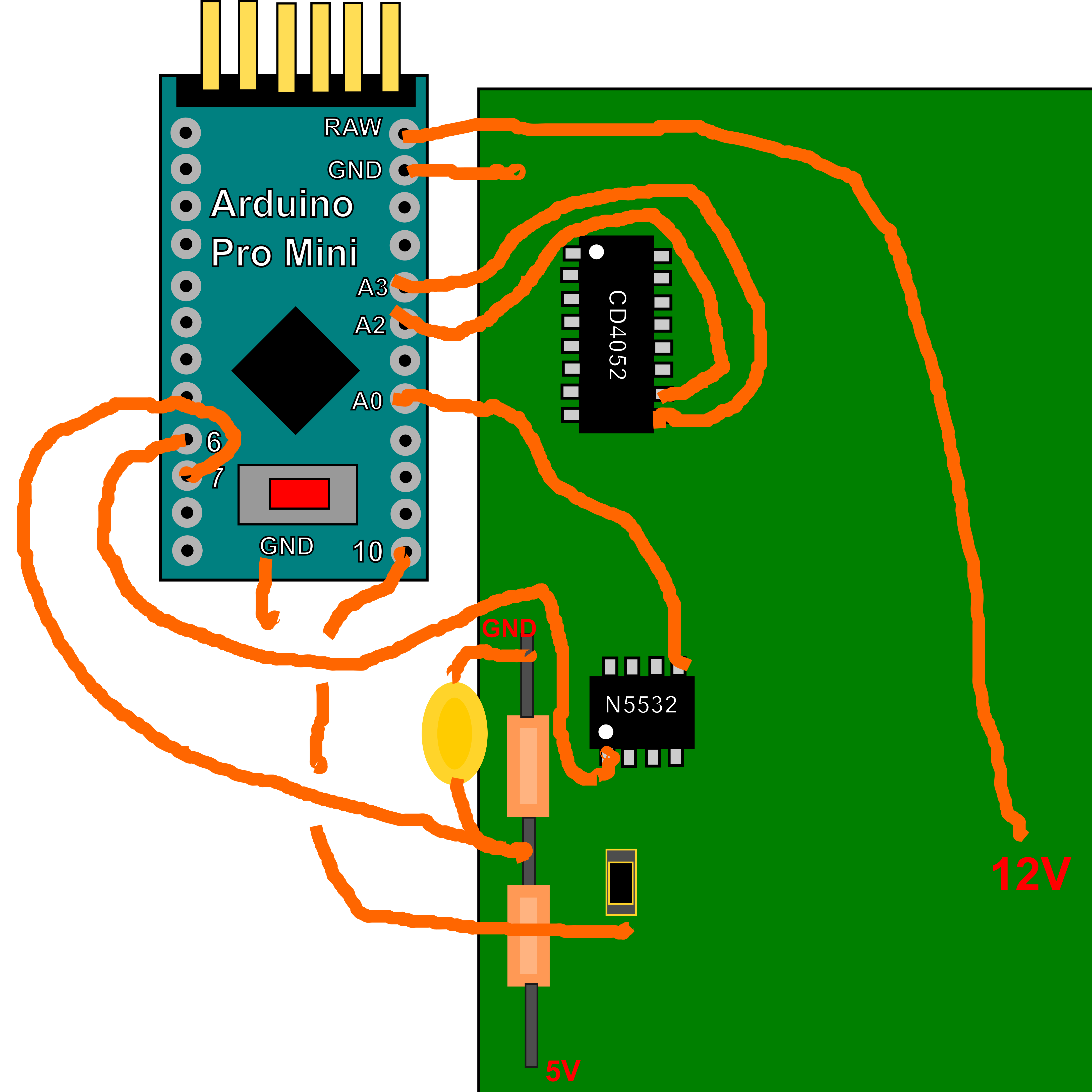
It is best to start with the ground connections, which should be short and using a decent thickness of wire. I would recommend at least 2 ground connections at opposite ends of the arduino, to the nearest ground on the pcb. You will have to scrape away an area of the car reversing kit pcb to solder to. The resistor voltage divider on the pcb is using a 33k and a 22k resistor with a 0.1uF capacitor to create a voltage of 3v which is the negative comparator input for the envelope detect on Arduino Pin 7. The positive comparator input Arduino pin number 6 , is connected to the filter output. The 2nd negative comparator input on Arduino pin A0 is the filter ground, which is available at both the non inverting inputs of the dual op amp. The other connections are from Arduino pins A2,A3 to the 4052 address lines on pins 10 and 9. (Do check the sense of these, so you get the corrcet addressing) . The next connection is the output that sends the transmit pulse. This is connected to the 4052 pin3 via a resistor. It should be possible to find it on the footprint of the microcontroller we already removed. On both of my versions of the car reversing pcb, it was connected to pin 3 of the microcontroller we removed. Finally connect the "Raw" input to the Arduino, to the 12 V power input (after the reverse protection diode if possible).![]()
Below is a video describing how to connect the Arduino to the car reversing kit pcb. Below the video is a diagram of the connections.![]()
-
2Construct the wind sensor frame
The test frame is very easy to make from ply and dowel as can be seen in the picture
![]()
TODO drawings and details of frame.
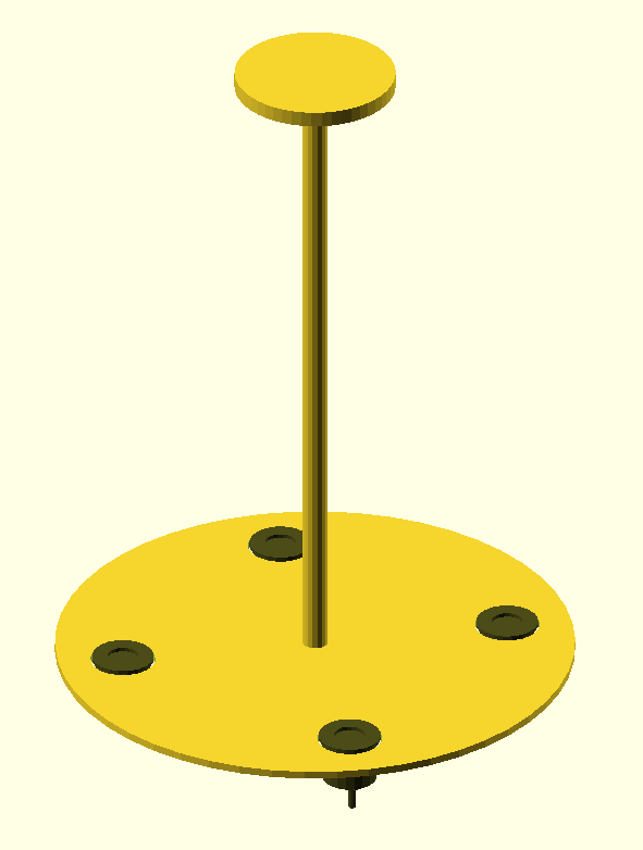
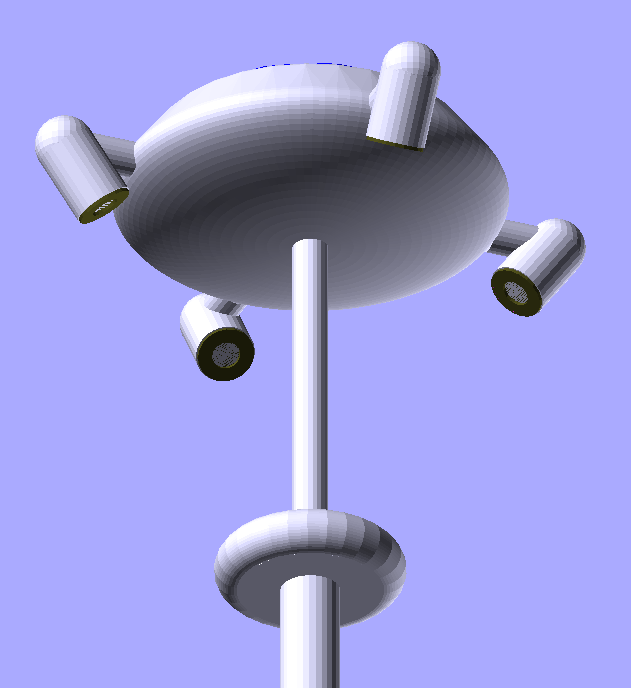
This is the proposed final long term version of the wind sensor. It is designed to go at the top of a pole.
![]()
The top is intended to take a solar panel from a solar fountain
![]()
-
3Connecting up
Installing and building the project
Firstly clone the Github Project
>$ git clone https://github.com/kwikius/ultrasonic_wind_sensor.git
Next in the resulting project directory, install the quan-trunk submodule using the following command:
>$ git submodule init --update --recursive
Start the Arduino IDE. Click on 'File > Preferences' and modify the sketchbook location so that it leads to the ultrasonic_wind_sensor directory.
Close Arduino and reopen.When Arduino reopens , click on 'File > Open' , navigate to the ultrasonic_wind_sensor/ArduUltrasonicWindSensor subdirectory and select "ArduUltrasonicWindSensor.ino".
Next click on 'Tools > Board' and select (AVR boards) > "Arduino Pro or Pro Mini".
Next click on 'Tools > Processor' and select "ATmega328P(5v, 16 MHz)"
Now select 'Sketch > Verify/Compile' to compile.
The code can be uploaded by attaching a serial cable to the Arduino Pro Mini and clicking Sketch > Upload.
Modifications
TODO Change the physical dimensions to those of your sensor. Modification of serial protocol for output to webservere
-
4Getting some output!
TODO More details
- Read data from Arduino serial port. By default, the sketch outputs text data via the Arduino serial port. You can connect to a PC with the same cable used for programming. The output can be seen using the Arduino Serial Monitor or another Serial port terminal app. Soon however this becomes quite limited. It is just a stream of numbers, so you might find it useful to attach the ESP-01 and visualise it using web sockets in your browser.
- TODO Visualise data using ESP32/8266 web server with GUI : https://github.com/kwikius/ultrasonic_wind_sensor/blob/master/ArduUltrasonicWindSensor/ArduUltrasonicWindSensor.ino
-
5Getting some output!
TODO how to tune the wind sensor for accuracy. (Actually it is not too bad without tuning).
-
6Programming ESP-01
Building and uploading the web server.
Assumes you are using the ESP-01. You will need a suitable programming fixture, such as described here
You also need to install the ESP8266 plugin for Arduino if not already installed, as described here
You need the following libraries in libraries subdirectory
- https://github.com/me-no-dev/ESPAsyncTCP
- https://github.com/me-no-dev/ESPAsyncWebServer
- https://github.com/Links2004/arduinoWebSockets
Start the Arduino IDE. Click on 'File > Preferences' and modify the sketchbook location so that it leads to the ultrasonic_wind_sensor directory. Close Arduino and reopen.
When Arduino reopens , click on 'File > Open' , navigate to the ultrasonic_wind_sensor/web_server subdirectory and select "web_server.ino".
Next click on 'Tools > Processor' and select "Generic ESP8266 Module"
Now select 'Sketch > Verify/Compile' to compile.
To Upload the code, connect the programming fixture via 3.3V Serial cable to your PC. Insert the ESP-01 in the fixture. Hold down both the Flash and Reset buttons on the programming fixture with the ESP-01 inserted. Release the Reset button while keeping Flash button pressed.
While keeping Flash button pressed. Select 'Sketch > Upload'.
Watch the output from the Arduino IDE. Once it is apparent that the code is uploading, you can release the Flash button, as it is only required to be pressed when the ESP-01 boots.
For initial programming of the web server you will need to use the programming fixture to set the Network parameters.
The WebServer requires the nextwork ID and password to connect to. If there are no saved parameters the web server will ask for those. N.B If using the Arduino Serial monitor for Serial IO, then set Carriage return as the end of line type and set baud rate at 115,200 baud. You have the choice to save the network parameters in EEPROM or not. If you choose not to save the parameters, they will be available until the web server is reset. If you choose to save the parameters they will be saved in EEPROM and will be used by default at reset. You can change the network you connect to by pressing Return ('\r') three times in 1st 5 seconds after reset. Again if you wish to save the new settings the old network settings will be overwritten, otherwise the settings you entered will be used unitil next reset.
Once the network parameters have been saved in EEprom, you can put the ESP-01 back in the wind sensor board.
(Note that you must be running the modified ArduUltrasonicWindSensor.ino for Atmega328 to talk to the webserver as described above)
With the wind sensor powered up, you should see the ESP-01 LED blinking. Once the LED goes out, it indicates the web server is connected to the network
The webserver is designed to support MDNS ( NOTE: Unfortunately this doesnt work in Android)
Open a web browser and enter "windsensor.local" as the URL. All being well, you should see the windsensor web page with real time data streaming from the wind sensor.
For Android, you will need to download an App such as Fing
-
7Tuning
TODO how to tune the wind sensor for accuracy. (Actually it is not too bad without tuning).
Wind sensor using car reversing kit
A wind speed and direction sensor from an Ebay car reversing kit and an Arduino

Discussions
Become a Hackaday.io Member
Create an account to leave a comment. Already have an account? Log In.