kwikius
-
Info on the original car reversing kit MCU
10/31/2021 at 11:33 • 0 commentsIn reply to https://hackaday.io/project/181677/discussion-169393
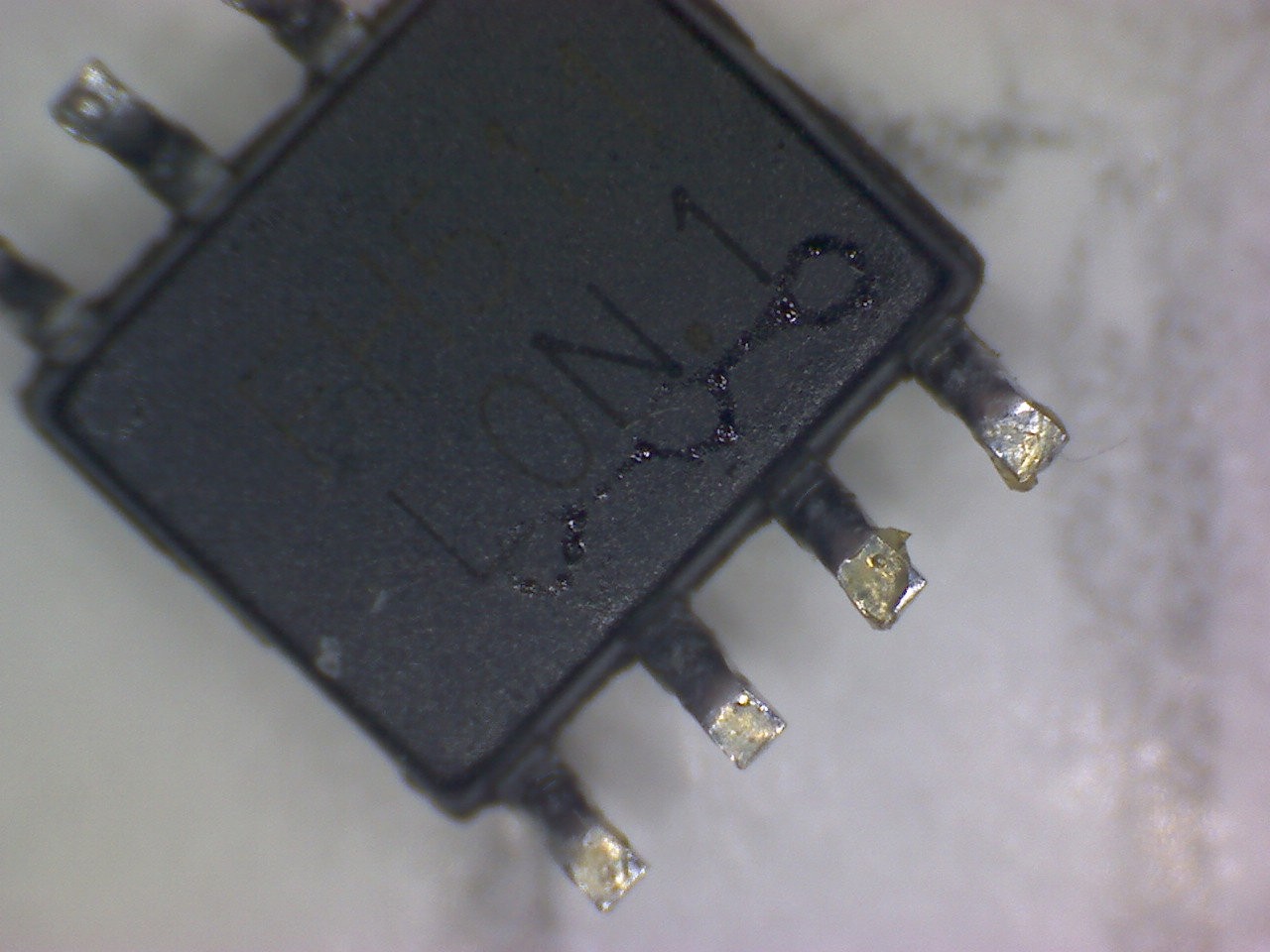
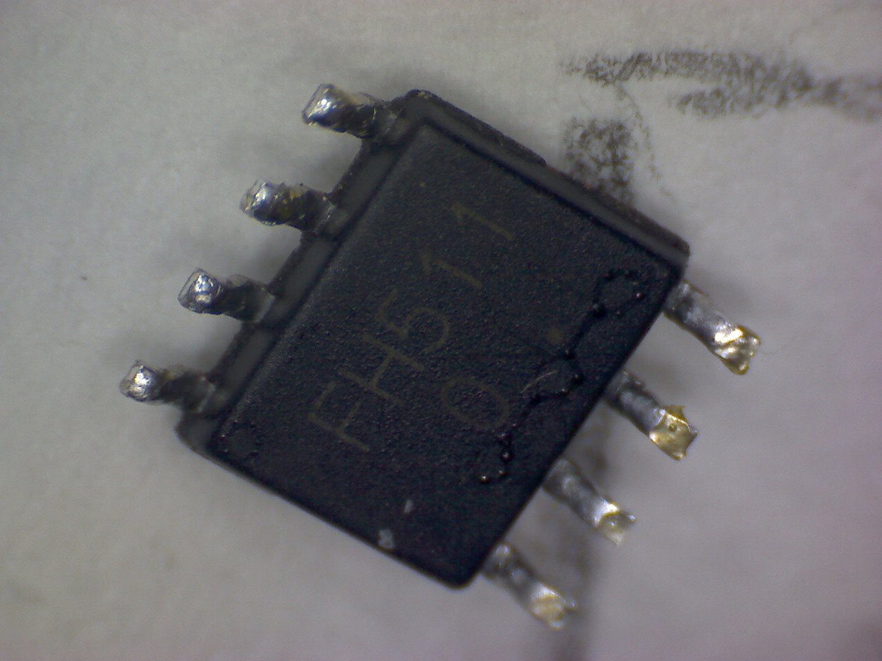
I had another look at the mcu that I removed from my 2nd version of the car reversing kit and saw it had chip markings on the underside. (N.B 2 pictures shown as for some reason the light obscures one or other dependent on angle )The markings say:
FH511
LON.1![]()
![]()
However I couldn't find anything useful by googling that!
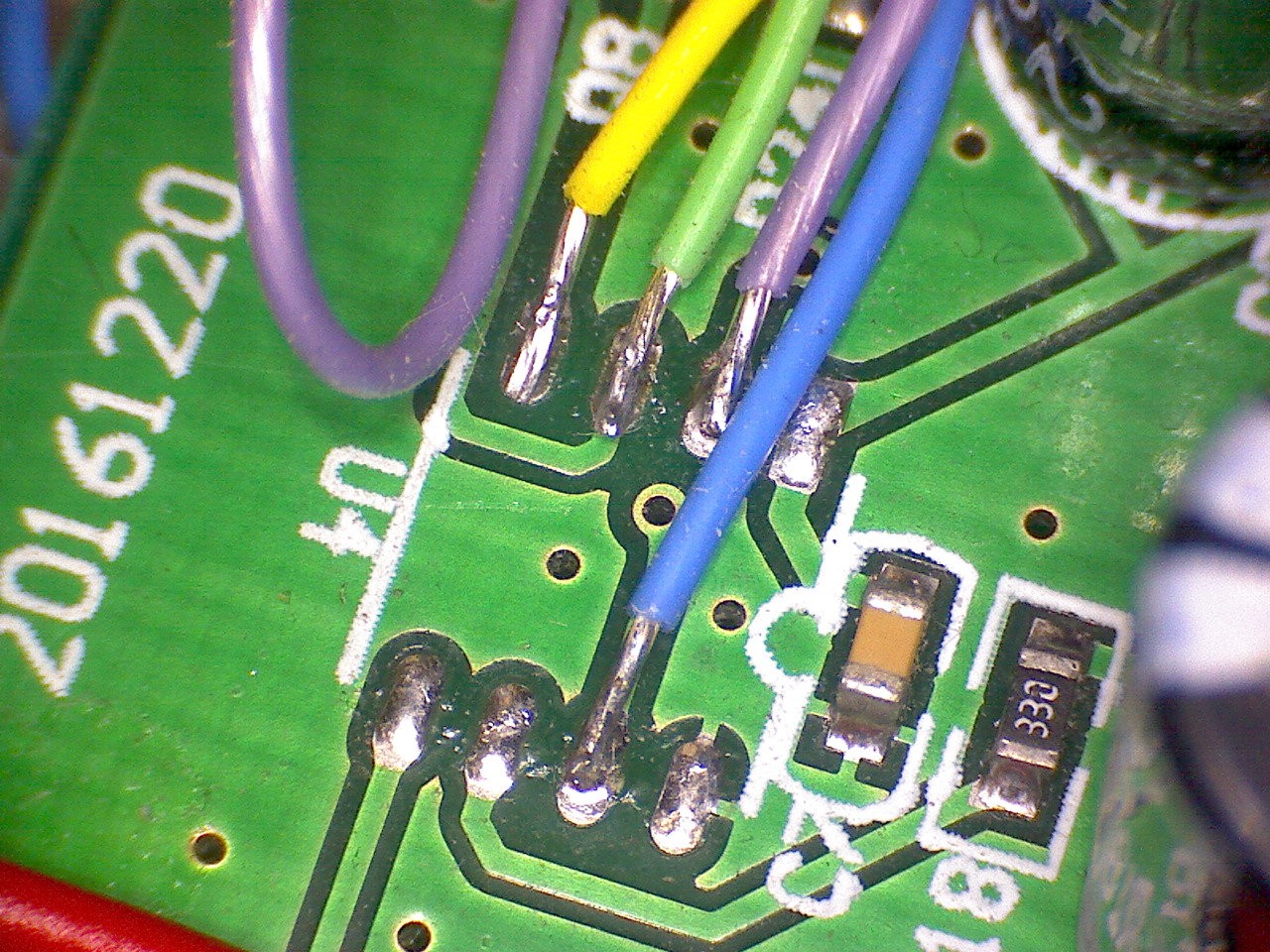
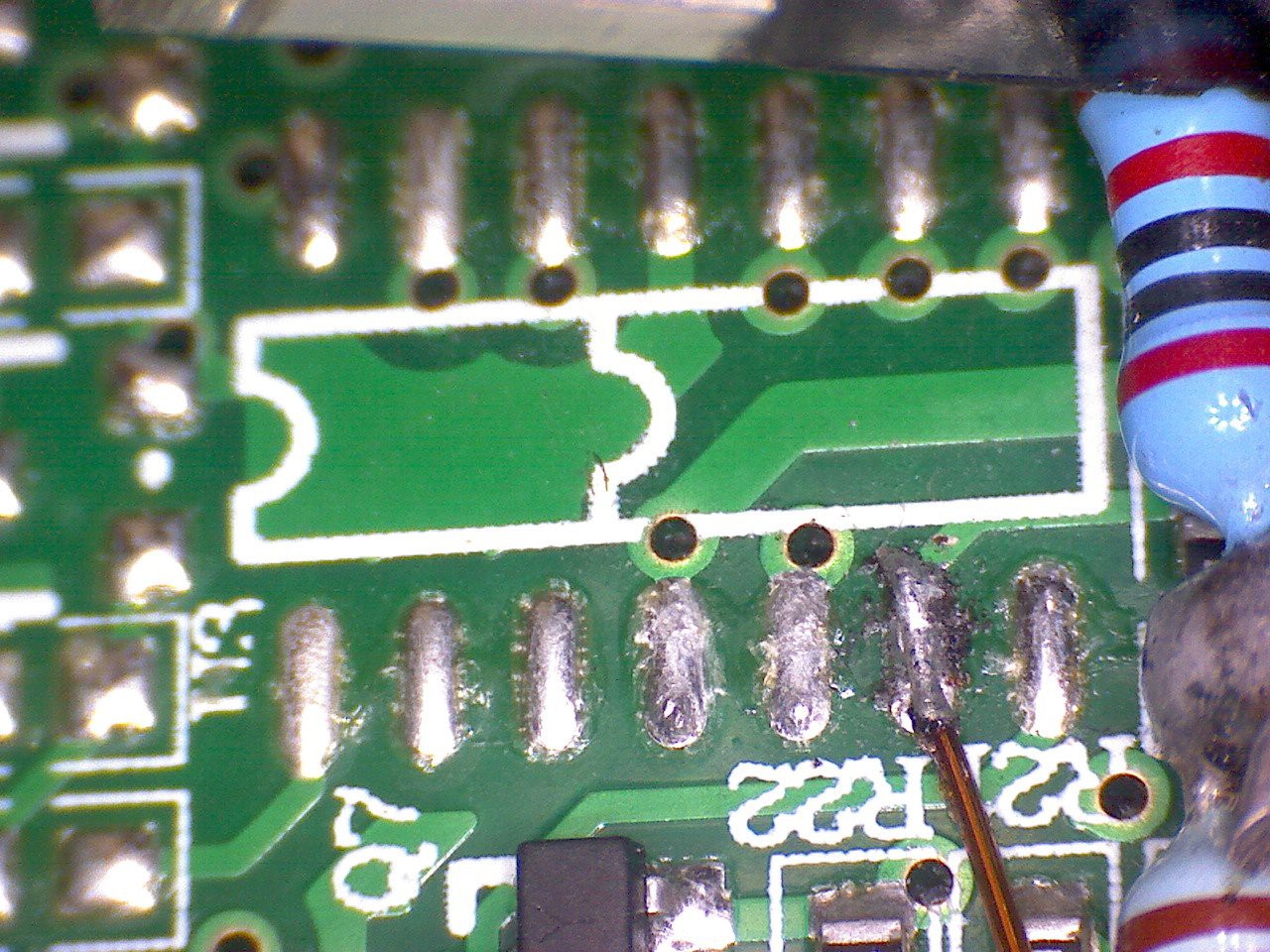
Here also are some closeups of the two footprints on the 2 different car reversing kit boards I have.
mcu footprint of first kit1 I bought
![]()
mcu footprint of second kit I bought
![]()
Here is why I think it might be a PIC12
The original MCU pinout ( based on the 8 pin footprint, but for both boards) v PIC12 footprint. I have only quickly studied the PIC12 datasheet and the pcb so data may be inaccurate!
pin number PCB MCU function PIC12F function Pin1 5V 5V Pin2 Transducer address out bit0 RA5 Pin3 Transducer drive RA4 Pin4 Pulse envelope detect RA3. T1G Timer1 (16 bit timer) gate, so could accurately capture flight time Pin5 monitor power? monitor Clk? RA2 SCL? Pin6 monitor data IO ? RA1 SDA? Pin7 Transducer address out bit1 RA0 Pin8 GND GND -
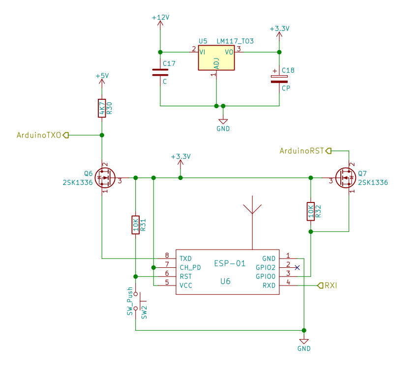
ESP-01 web server schematic
10/24/2021 at 16:43 • 0 commentsSchematic for ESP-01 web server allowing the wind data to to be presented in real time on a web page.
Transmit out to Arduino is not used at the moment, but would be a nice option, if you can fit it on the board, so one day Sensor could be configured from web interface. ArduinoRST goes to the Arduino reset line. RXI is the wind sensor data from the Arduino using a voltage divider (not shown here) (2.2K / 3.3K resistors) to drop the voltage to 3.3V. NPN transistors could be used instead of mosfets Q6 Q7, but they would need bases to be connected to 3.3V via (say) 10K resistors. The mosfets were selected because they use slightly fewer components. Voltage regulator should ideally be a TO220 or similar with a good heat-sinking capability as it has quite a voltage drop, when powered from 12V and the ESP-01 does use 100 mA or so when in WiFi transmission mode. R32 is required to prevent the ESP-01 starting in programming mode. Adding a reset button to ESP-01 is always a useful feature too!
TODO.
- Do a video describing more details of the circuit and how it fits on the car reversing kit PCB.
- Update github project with sub-modules to include required web server libraries.
- Explain how to upload code to ESP-01 etc
Source code for the web server here:
https://github.com/kwikius/ultrasonic_wind_sensor/blob/master/web_server/web_server.ino
![]()
-
Add ESP-01 to the hacked car reversing kit PCB.
10/12/2021 at 10:06 • 0 commentsUpdate the add on board with ESP-01. Once added to the board Initially I found that ESP-01 had difficulty connecting to the network. I suspect that it is due to noise on the hacked PCB , since connection works fine, if the Arduino is held in reset. That being the case, I solved the problem by connecting the ESP-01 GPI0 to the Arduino RST input ( via suitable level shift). Now When ESP-01 wishes to connect , it puts Arduino in reset and takes Arduino out of reset once connected. This works well as a solution on the demo board. Once connected the Wifi is smart enough to avoid the noise frequencies and the connection seems to be robust enough for testing and demonstrating.
https://github.com/kwikius/ultrasonic_wind_sensor/blob/master/web_server/web_server.ino#L105
TODO: Provide circuit details for ESP-01 and a video of the updated board
-
Use custom polledSerial serial port class rather than Arduino.Serial
10/08/2021 at 12:10 • 0 commentsThe windsensor project is very critical on interrupt timing to capture the pulse length. Looking at the Arduino.Serial code, it does (of course) use interrupts and even disables the global interrupts during a write. In this application a simple polled serial port will do the job without globally disabling interrupts and without serial write interrupt getting in the way of the envelope detect or zero crossing interrupts, so the Arduino code was modified to use the custom polledSerial class.
-
Added info and video on connecting up the Arduino
10/07/2021 at 16:06 • 0 commentsAdded video and info on how to hook up the Arduino to the extended car reversing kit pcb
-
Use atmega328p internal comparator instead of external comparator.
10/05/2021 at 19:35 • 0 commentsTo get the project working originally I used an external comparator. The comparator is used first to measure the magnitude of the received pulse stream and then to detect zero crossing, by means of positive feedback which moves the trip level between the two levels dependednt on output state
I wanted to use the internal comparator and eleiminate theat extra component. One problem with the internal comparator is that the outout doesnt go to a pin, which means the traditional positive feedback cant be used. I originally decided to use a spare pin as an output and use it to set positive feedback to the input it in the comparator interrupt, but then I realised I could just use 2 different comparator channels and switch between them in the comparator interrupt. After some headscratching and layout issues this is now working well and I plan to stick with this option for the moment. This is actually a much nicer option since it doesnt put any load on the output and samples the filter ground directly rather than a voltage which is around the same level as I was doing with the external comparator. I also would hope that the settling time is much reduced since both of the negative outputs have constant values, one at filter ground and one at envelope detect voltage and the filter output is not loaded at all.I also got v2 of the circuit working using the car reversing pcb in the videos, which is much neater than V1, so now need to do a new video about it all.
-
Modify source code to work without requiring main to disable interrupts
09/30/2021 at 13:58 • 0 commentsModify source code so that we don't need to disable interrupts. Important since the comparator is meant to have a lot of positive feedback, which has to be done in software in an interrupt, while only around 6 usec is available to flip the output.
https://github.com/kwikius/ultrasonic_wind_sensor/commit/9627a261ac55dd3647f3f7eb349310b97648b39b -
Remove the existing mcu with a hot air soldering iron
09/30/2021 at 07:10 • 0 commentsThe existing 8 pin soic mcu has to be removed. I have a hot air soldering iron for this task. (If you don't have one, then it is possible to remove smd ics by making a u shaped piece of thick copper wire and soldering it to the ic's pins with blobs of solder. Heat it up with a bigish soldering iron and then pull it off with tweezers)
Also shown in the video is the piece of proto board, attached to the existing pcb with double sided tape, which works much better than you would think..
-
Cut out and fit proto board to add area to reversing sensor control board
09/29/2021 at 10:13 • 0 commentsCut out and fitted the proto board to add some area to the original PCB.
In the video I mention knitting the 2 boards together with copper wire. To line up the boards for drilling, I joined the board with doubles sided tape. Once done, I discovered that the result was strong enough just using the tape, which makes life much easier. Next todo is to remove the MCU with a hot air soldering iron, so will see if the proto board falls off with the heat!
-
Added comparator output to circuit description
09/19/2021 at 12:23 • 0 commentsAdded comparator circuit to circuit description.
Wind sensor using car reversing kit
A wind speed and direction sensor from an Ebay car reversing kit and an Arduino