 Christian
-
1Pinouts and Wiring Diagram
I was able to find a Hardware and Driver reference document that explained the pinouts, handshaking protocols, and low power sleep mode handling for some Palm Pilot Keyboards that were similar but not the exact model of keyboard that I had on hand (specifically model P10802U, user's handbook for reference).
Hardware and Driver Reference: http://www.splorp.com/pdf/stowawayhwref.pdf
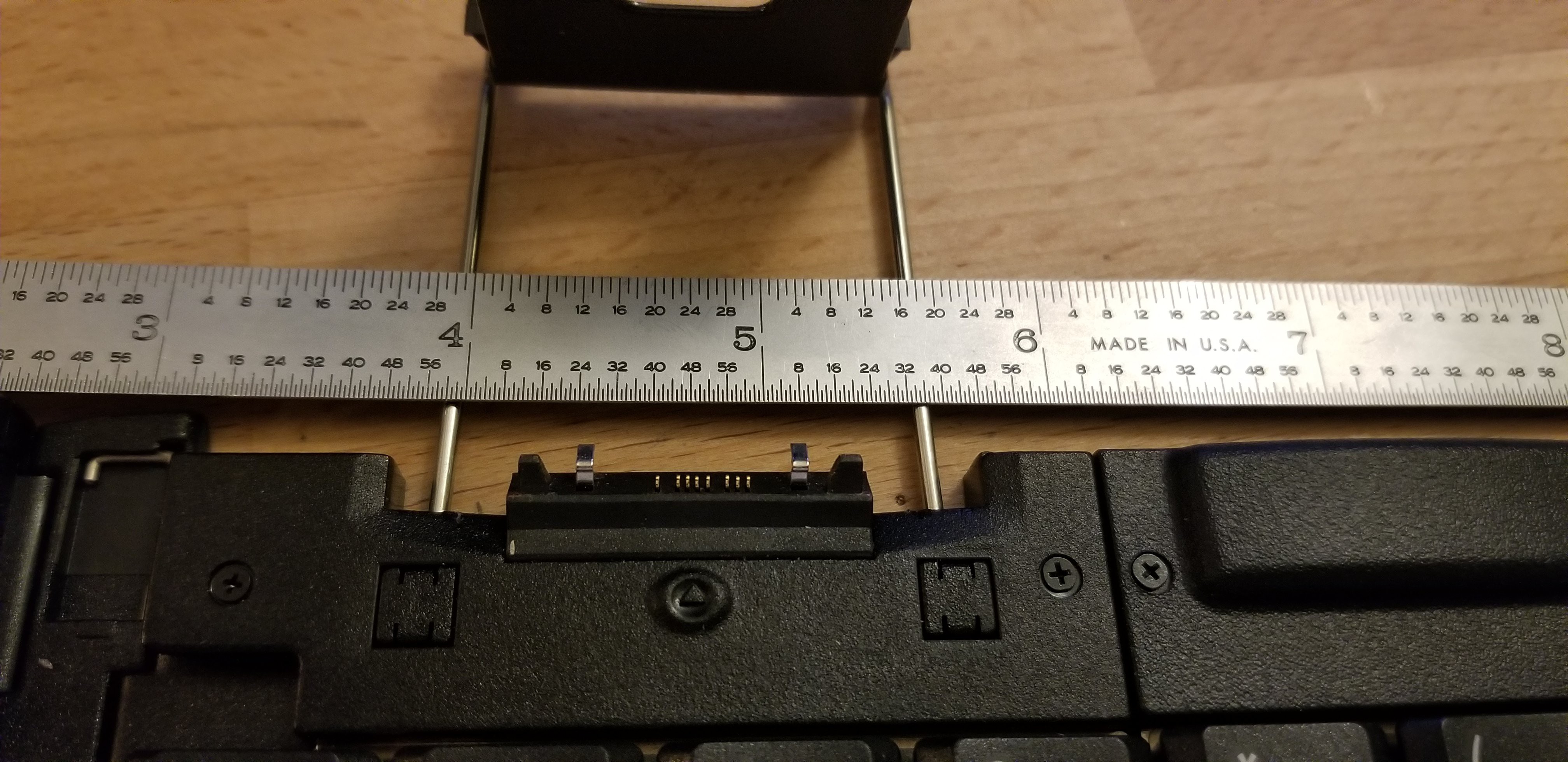
My particular keyboard only had pins 5, 7-10, and 12-14 present at the interface.
![]()
Pin Name 5 Hot Sync (DCD) 7 Gnd 8 ID (leave open for keyboard) 9 Vin (3.3V) 10 RxD 12 Peripheral Detect (tied to gnd by keyboard) 13 CTS (unused in handshake, but tied to Vin by keyboard) 14 RTS
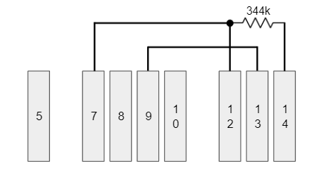
I did some continuity and isolation testing on the keyboard pins and I found that pin 12 (peripheral detect) is tied to pin 7 (gnd), which is consistent with the documentation. I also found there to be about 344kOhms between pins 7 (& 12) and pin 14. Additionally, pin 13 (CTS) is tied directly to pin 9 (Vin). During the handshake, the palm pilot should look for CTS to go high, indicating that the palm pilot should be ready to receive data. Since the keyboard leaves CTS as always-high, it isn't actually needed in the handshake procedure... we can just assume it's always high.![]()
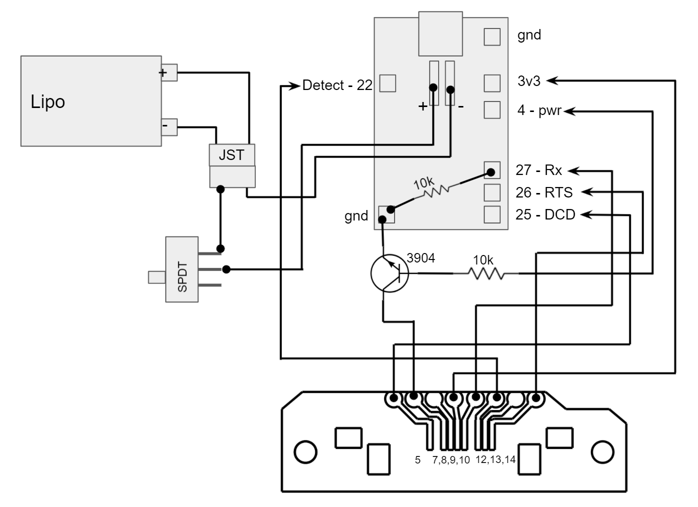
Now, to wire this up to the TinyPICO. Most of the GPIOs can be used, but I tried to avoid any pins that were shared by the USB port or any pins that were unpredictable at startup.
TinyPICO
PinName PPK Pin 4 Power Enable 7 (via 3904 transistor)
*see schematic22 Detect 12 25 Hot Sync 5 26 RTS 14 27 RxD 10 ![]()
-
2Circuit Board, Wiring, and Soldering
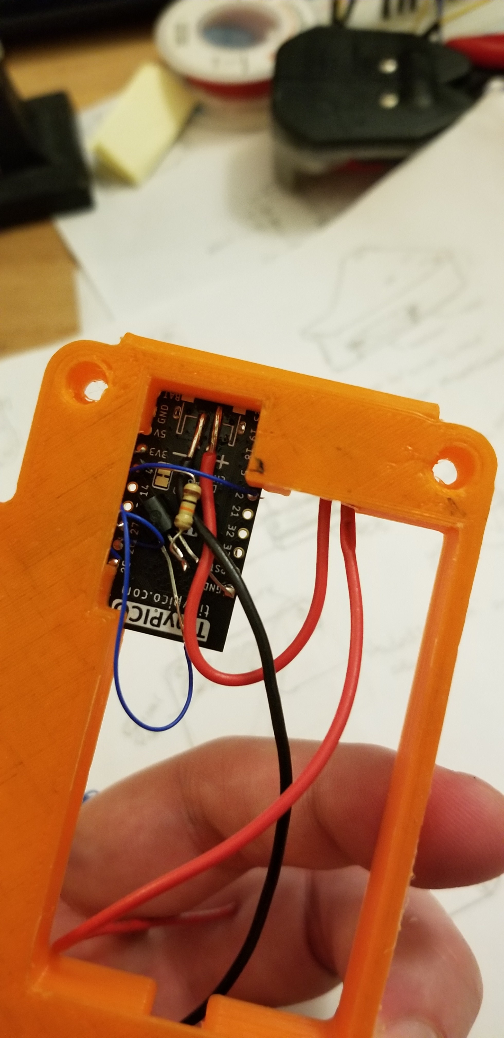
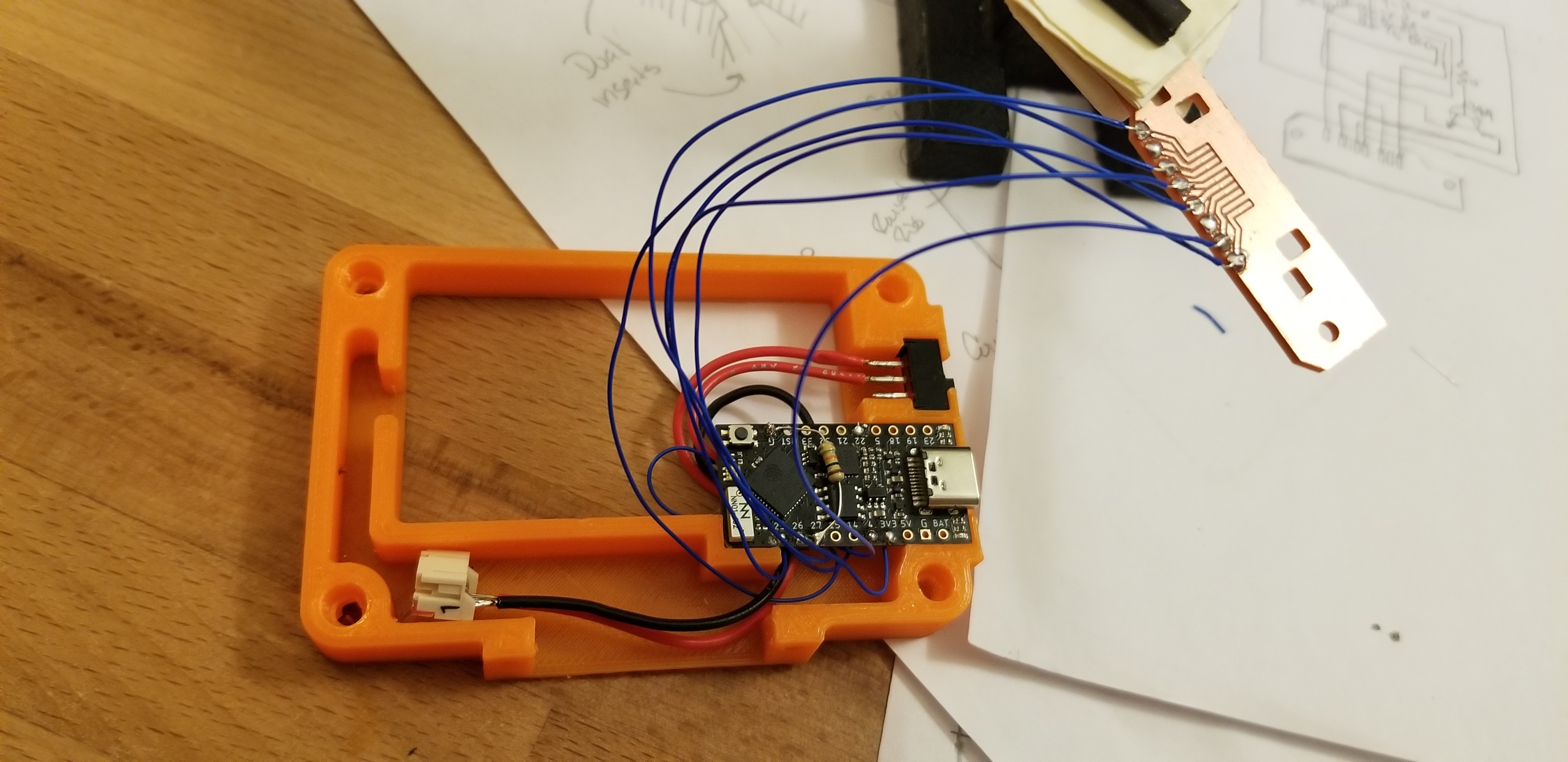
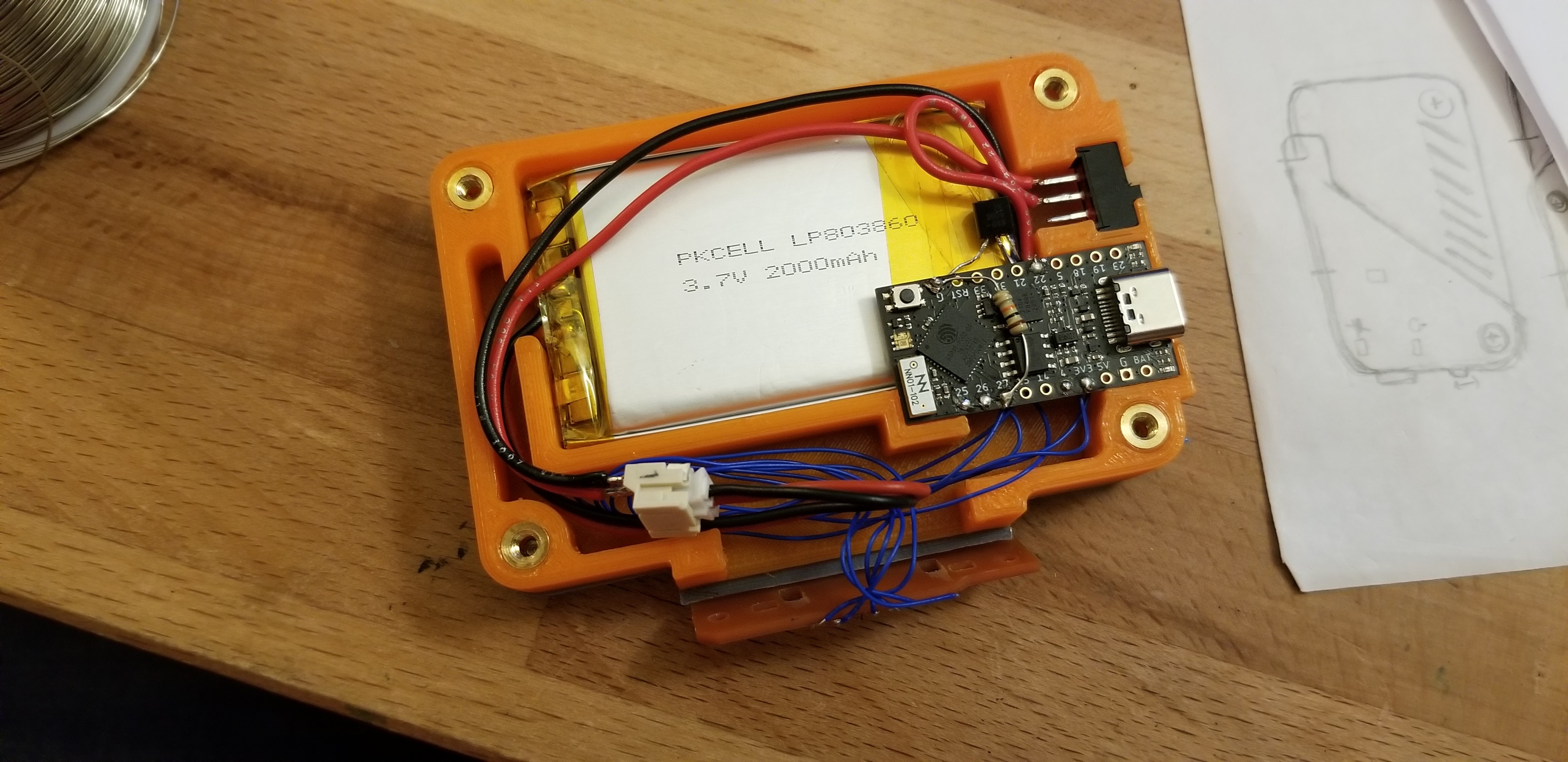
I used 30 AWG solid core wiring for each of the signal connections, but 22 AWG stranded wire for the battery connections and power distribution. The TinyPICO has pads ready to go for a JST battery connector, but it faces the same direction as the USB, and since I overlapped the TinyPICO and the battery, there wasn't enough space to solder the JST connector directly to the board. Also, I wanted to include a power switch on the device between the TinyPICO and the battery. I soldered the JST connector to the TinyPICO interface with a couple inches of wire in between.
![]()
In the above picture, the 3904 is directly underneath the TinyPICO - I ended up relocating it after this picture was taken. There isn't enough space under the TinyPICO to fit much more than the resistor.
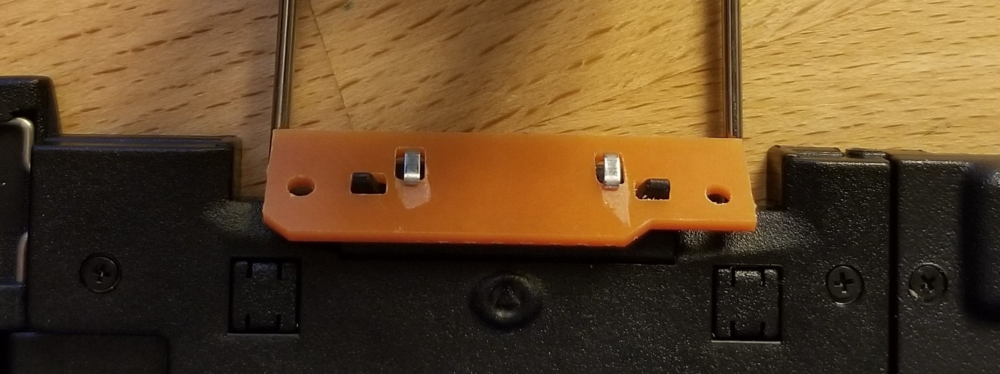
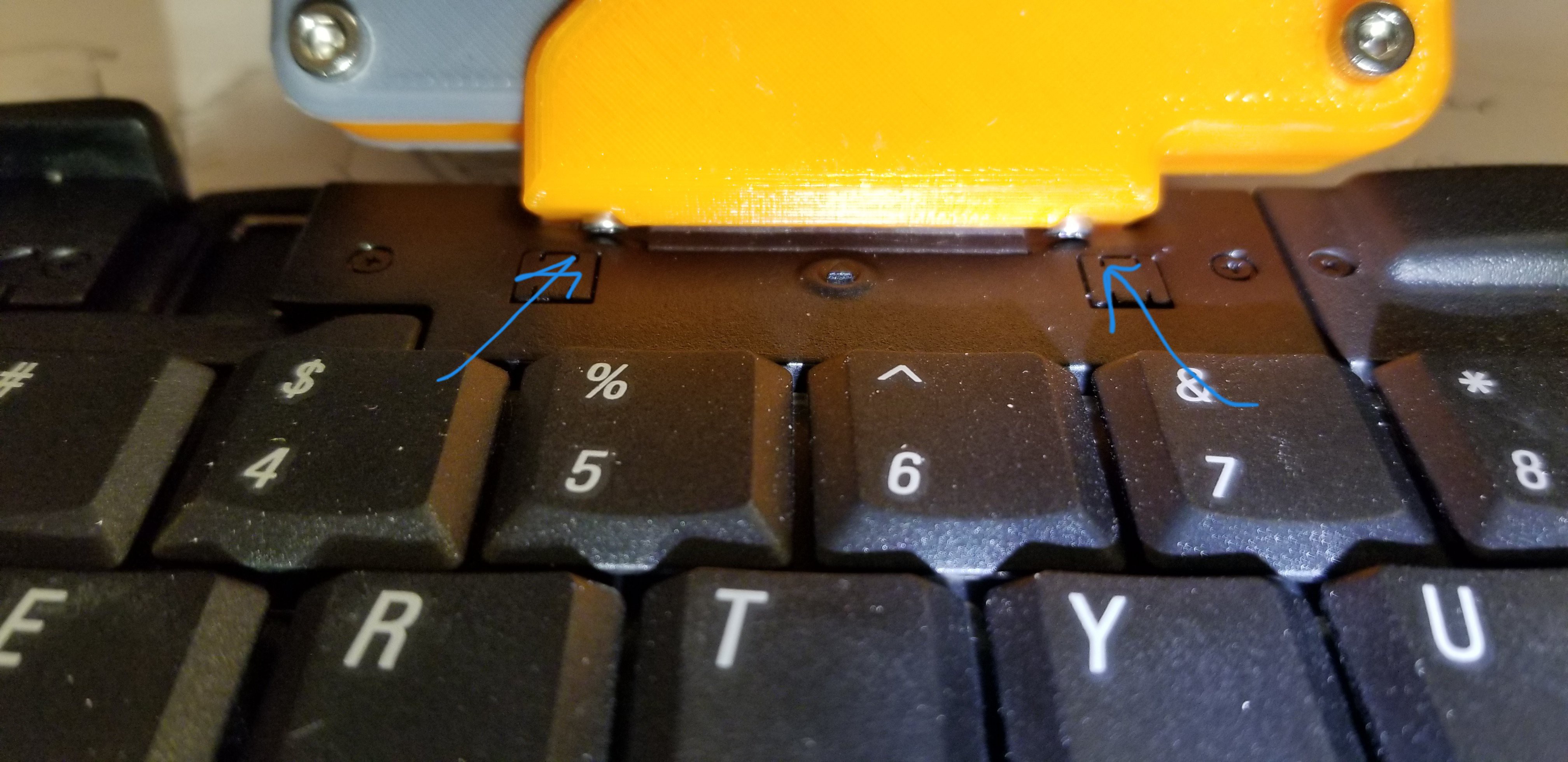
A note about the PCB: The thickness of my single-sided copper clad was 1.35mm, which was slightly too thick to fit underneath the flexible metal retaining hooks on the keyboard. I had to flip the board over and scrape away some of the fiberglass with an XActo knife. I'd estimate at least 0.3mm was removed.
![]()
Just give the board a couple of fit checks before you start soldering to it.
![]()
Tuck the wires over the top and around the back of the PCB as closely as you can. There isn't much clearance between the solder points and the 3D printed cover (installed later).
![]()
There's a boss on the 3D printed cover that will press down on top of the big, main chip on the TinyPICO, so make sure you route the 10k pulldown resistor AROUND the chip and NOT OVER it.
-
3Mechanical Assembly
I used a soldering iron to press the brass inserts into the 8 threaded interfaces on the 3D printed "frame" (4 inserts each side).
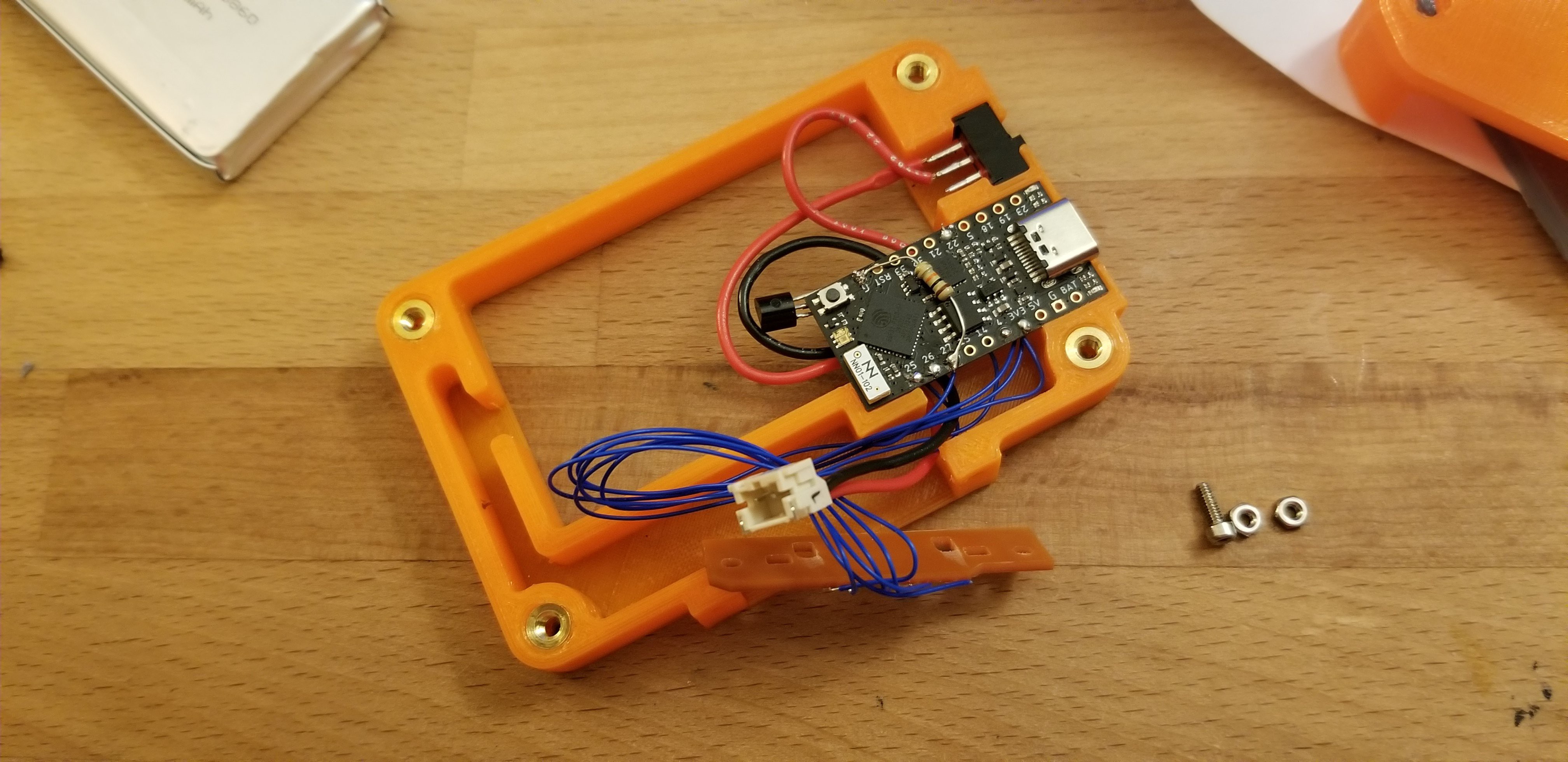
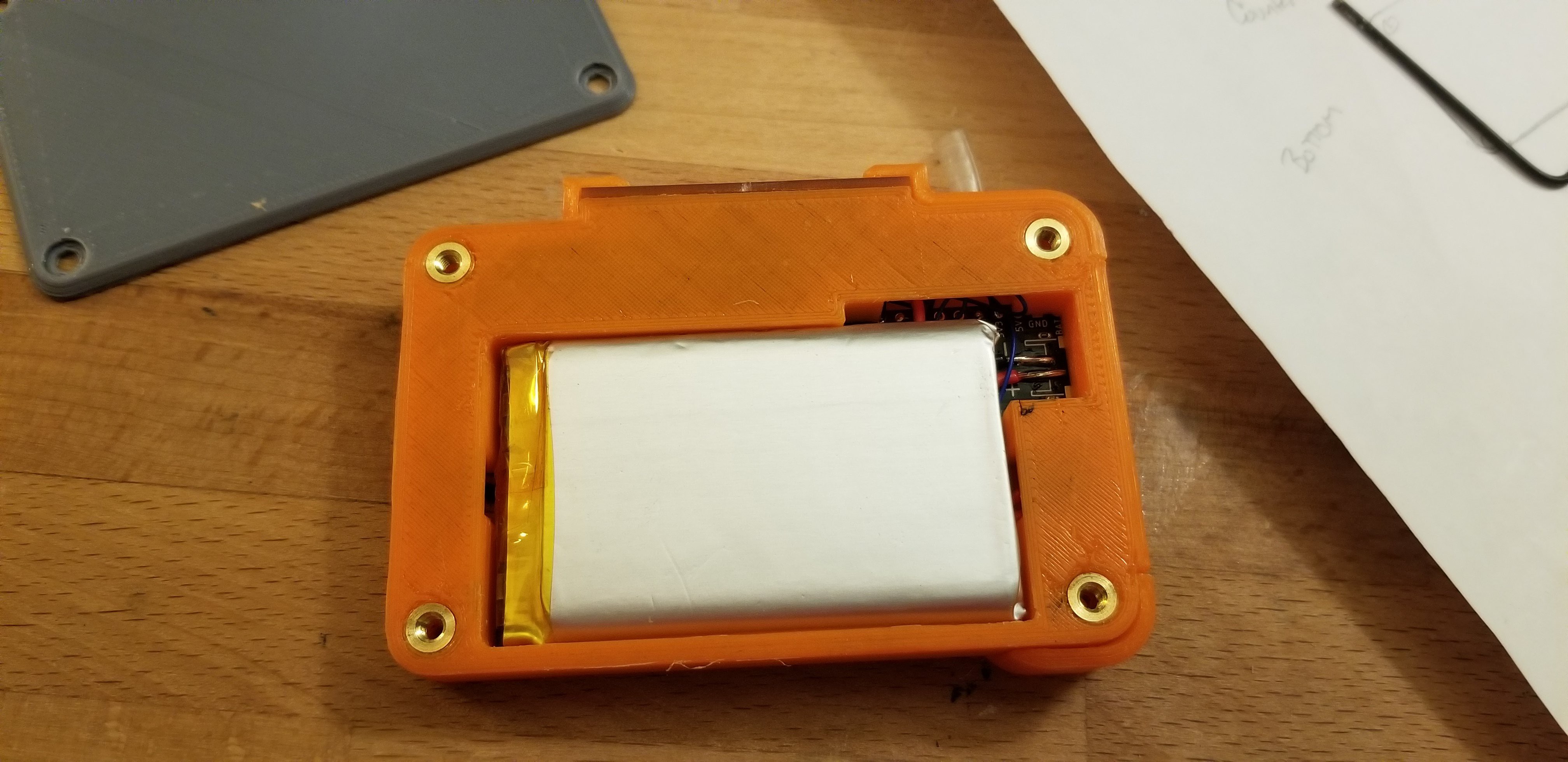
Pop the switch and the TinyPICO into place and tidy up the wires. Insert the battery from the bottom side of the bracket. Make sure the switch is in the OFF position, and plug in the JST connector.
![]()
Install the rear cover.
Flip the assembly back over and tuck the wires into the channels as best you can. Set the M2 hex nuts into their respective slots.
![]()
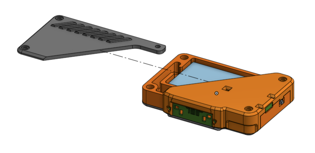
Hold the circuit board roughly in place and slide the enclosure lid (the lid half WITHOUT THE RIBS) down over everything. This lid will sandwich the circuit board in place. Carefully insert the 2x M2x10 button head screws through the cover and the circuit board, and into the pre-placed nuts inside the frame.
![]()
Most standard socket head screws will not fit in this location. Standard M2 socket head screws stick out too far and will prevent you from installing the module. Trust me, I tried:
![]()
:-(
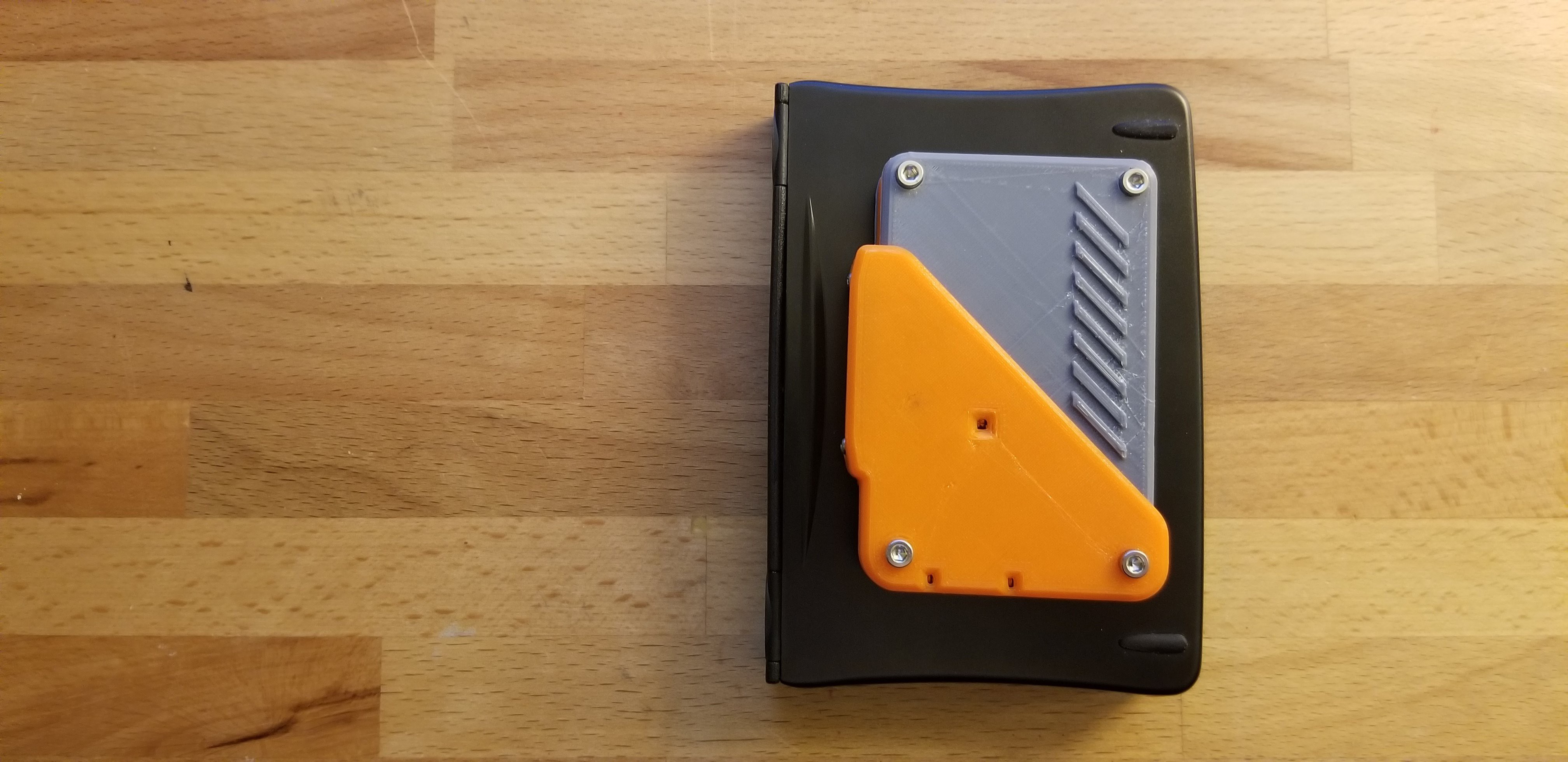
The last step is to slide in the other half of the lid sideways, being careful not to pinch any of the wires. The thicker half of the case needs M3x10mm screws. The thinner half takes M3x5mm screws.
![]()
Et Voila.
![]()
Palm Pilot Keyboard Bluetooth Conversion
Converting a Palm Pilot Portable Keyboard into a Bluetooth keyboard using a TinyPICO ESP32

Discussions
Become a Hackaday.io Member
Create an account to leave a comment. Already have an account? Log In.