Timescale
-
A small gesture
10/31/2021 at 16:59 • 0 commentsAlthough the project is currently on hold, I continue playing around with the LiDAR sensor to explore the possibilities of using a robot sensor as a static interface device. Last time I uploaded the basic multispot code that tracks several groups, averaged them and checks these against a set of pre-defined points in space. Functionally this is about all a simple interactive activity in a space should ever need. This script could do with a little refinement like considering accuracy based on distance and/or position, but basically it just works good enough from desktop use to small rooms. I'm quite sure that implementing this in a big exposition room will be just fine and will require little tweaks.
So having that functionality basically down, I started to look at using the sensor as a pure HID again. The proof-of-concept LiDAR mouse pointer script was quite basic. It worked by closest point, could not track multiple point groups and has no smoothing. It also did not nicely map the data to the screen coordinates. The obvious next step was to take the grouping method and use that for the HID and try to implement all the necessities to make it a workable input device.
The file isn't quite ready yet to upload for everybody to play around with, but I thought it useful to share my ideas on it so perhaps somebody with a better idea could comment or ask a question. The majority of choices I make in tinkering with this was that I could very well make it so that apart from driving the cursor, I could also perhaps implement gestures in some form.
Initially I am using group 0 for the pointer. so no matter how many groups are created, only the first one will control the cursor. This is fine for testing purposes and trying out different smoothing techniques. The smoothing trick I found to be the nicest one, I.E. the one that gave the least jittery cursor and the best control was a single step smooth with a vector and velocity value to impact the amount of smoothing. The velocity of course we get for free because in single step smoothing you retain the old position and find the difference between that and the new one. That value is also smoothed, albeit linearly whereas the we smooth the position data based on how the smoothed velocity matched the vector.
This way, movement in any direction always gets a bias, meaning that quick motions do not take to long to catch up and slow movement give fine control. All the small jittering from the sensor data is also smoothed quit aggressively which means you get a cleaner cursor movement in all ranges.
Now I'm sure that the vector method is quite overkill, but the reason I stuck with this was because I realized that IF this got me precise enough results, it could be used to do the same with the second group and based on the vectors and velocity, this could drive other events like zoom, pinch or any spacing 2d gesture the sensor could pick up.
So this is my thinking right now. Get the cursor as smooth as possible and then try and implement gestures for two hands/ people. Hopefully next time I will have some code to share.
-
Multi spot with output.
10/19/2021 at 13:59 • 0 commentsHaving had some time to test various methods, I believe that I am pretty close to a full functioning driver script that can be used to interact with a set of predetermined set of spots or targets. I will upload the scripts in their current form for anybody to play around with. Mind, these are crude and the result of a very iterative process of hit and miss.
The most advanced version uses the dot-grouping method, converting them to Cartesian for later processing. The next step to to average the group into a point and see if the point matches the pre-codes targets.
Being mainly a desktop experiment at this point, the values for including or excluding points from groups or determining of a point hits a target are rather crude. For instance, in the group phase, there is no accounting for angle vs. distance. This should be easy to implement at a later stage. As soon as the Cartesian coordinates are available, this does not matter anymore.
Finally, for a target to be activated, it has to be actively scanned 3 times. After that it does an action and sets a flag. Every time an object is detected on that target, it will set the detection counter + 2(for ugly bad code practices reasons!). The loop always subtracts 1 from the counter. When the counter reaches zero, another action can be performed to signal the target is now empty.
In the script, the actions for activating the target are generating a uppercase letter for a front-end application event. When the target is deactivated, the same letter will be send in lowercase. This means you can pre-define 26 spots theoretically. If spots are not blocking the line of site of the LiDAR, the script can track multiple active targets for multiplayer purposes.
You can find the scripts in the file section of the project.
-
Multi touch maybe?
10/03/2021 at 13:41 • 0 commentsHaving toyed around with my LiDAR sensor for a week, I have some workable scripts that could be used for an input device. The first and simplest method is to have an array of locations. When the sensor picks up a signal from that general area, an action can be performed. In the example code, the nearest reading is used and checked against the array so multiple spots can not be triggers simultaneously.
for i, scan in enumerate(lidar.iter_scans()):
    dist = 10000
    for x in range(len(scan)):
        if scan[x][1] > 270 or scan[x][1]< 90: # field of view
            if scan[x][2] < dist:
                # new nearest point
                ang = scan[x][1]
                dist = round(scan[x][2])

   # Check array for matching points
   # print('Angle : %.2f' % ang + ' distance : %.2f' % dist)
    curSpot=0
    for chkSpots in spots:
        #chk difference in degrees for all spots
        a = chkSpots[0] - ang
        angDiff = abs((a + 180) % 360 - 180)
        if angDiff < 3:
            #Difference smaller than threshold. Check distance.
            if abs(dist - chkSpots[1]) < 25:
                #Spot is occupied. Trigger code goes here
                print("Trigger : " + str(curSpot))
        curSpot += 1
This method works pretty well on small and large scale. The trigger action could be anything from a mouse event to a keyboard action, whatever the front end of the project requires. This is of course a very crude example and could be refined in various ways. In all the experiments I have not done any smoothing over time for example where over multiple scans the results are checked at past results and "smoothed" as it were. The current readouts can be quite jittery, but for simple interactions, basically you need only one good scan to trigger something. Anomalous readouts when there is nothing to be scanned really do not occur.
But what about generating X,Y coordinates? Using the first script as a base, that is also not that difficult.
    x = math.cos(math.radians(calcAng)) * dist
    y = math.sin(math.radians(calcAng)) * dist

    if dist < 750: # limit not to make the cursor go crazy
       pyautogui.moveTo(screenCenter + round(x ), round(y ))
This basically give a very rough and non-calibrated control of your mouse cursor and works remarkably well. I left a couple of bits out which are unique to my setup, quirks and mistakes, This is still based on a single point which is the closest during one scan cycle and of course due to it not being calibrated, it does not cover the entire screen. This should not be to hard to do as pyautogui has easy functions to help with that.
But it is quite obvious that this method would be fairly workable for example where an interactive area reacts to, for example, onmouseover events in a browser.
Multi touch
But how far can this be pushed? Could it do a rough kind of multi touch for a quiz game of something like that? It is obvious that this sensor has hard limits apart from distance and certain environments. The most obvious one is that it can not detect multiple objects if these object obstruct each other.
But with some imagination, there is potential here. If only it could detect of track say 4 points simultaneously. You could do a two player game where their position would indicate an answer to a multiple choice question. It could be anything really!
Obviously the "nearest point" approach is not very useful here. We need to gather clusters of points and subsequently determine if these are the same object. The ranges I use are rather arbitrary in the examples, but they do work quite well at close range.
for x in range(len(scan)):
        if scan[x][1] > 270 or scan[x][1]< 90:
            if scan[x][2] < rangeLimit:
                # point in within scanning distance.
                ang = scan[x][1]
                dist = scan[x][2]
                if len(spotAng) -1 != group:
                     #first point detected, Add point to first array
                     spotAng.append(ang)
                     spotDist.append(dist)
                     spotNumber.append(1)
                     calcAng = round(ang - 270)
                     x = math.cos(math.radians(calcAng)) * dist
                     y = math.sin(math.radians(calcAng)) * dist
                     spotX.append(x)
                     spotY.append(y)
                else :
                     # still in same group.. Check for angle
                     a = spotAng[group] - ang
                     angDiff = abs((a + 180) % 360 - 180)
                     #print(angDiff)
                     if angDiff < 3: #if difference is less than 3 degrees
                         if abs(dist - spotDist[group]) < 40:
                             # distance is alo within the same area.
                             spotAng[group] = ang
                             spotNumber[group] += 1
                             spotDist[group] = dist
                             calcAng = round(ang - 270)
                             x = math.cos(math.radians(calcAng)) * dist
                             y = math.sin(math.radians(calcAng)) * dist
                             spotX[group] += x
                             spotY[group] += y
                         else:
                             group +=1
                     else:
                         #out of bounce
                         group += 1
First when a point is detected, It gets put in the first arrays. If subsequent points are within its distance and angle range, these get added to that array, if they do not, they next points gets a new set of arrays. This could be done a bit cleaner with a multidimensional array, but that is for another day.
Note that I also calculate the X and Y coordinates in the part and not the next. The reason for this is that I average the points in the array and eventually I want to do an extra check of point distance of these results. This is easier to do with coordinates than with degrees, but for that to work and not have an extra loop it has to be calculated here.
The final part is just about where I'm at right now. There are various ways to use the collected information, but at the moment I just plot the results of the first group to the mouse cursor.
   for spots in range(len(spotNumber)):
        spotX[spots] = round(spotX[spots] / spotNumber[spots]) * 3
        spotY[spots] = round(spotY[spots] / spotNumber[spots]) * 3

   if (len(spotAng) > 0):
        print(spotX[0])
        if dist < 750:
            pyautogui.moveTo(560 + spotX[0] , spotY[0] - 200 )
Pyautogiu does not support multi input I think, but with this simple test, I have noticed that rounding the clusters of points make for a pretty robust pointing device. If you print out len(spotNumber) you can see the points it has detected. It goes up to 8 without difficulty (as long, of course, nothing is obstructing something else or are to close to each other).
You could also implement the spot detection method on this principle and I think I will because for a multi input coordinate system, this will not work as is. However, for single input coordinate systems, this is far superior to the nearest point method.
For single input, this method also has the option to detect interference and ignore it. Say, somebody is occupying a spot, and somebody walks in the area. In this example, this person could now take over the first position depending where they stepped in, but some simple checks could detect this and ignore the second input.
Thus far my experiments with the LiDAR data and how this could be implemented as a HID. For the next log, I'd like to have advanced features like smoothing, intrusion detection and calibration working and at that point I'll probably upload some of the Python files in their entirety.
-
Defining function
09/27/2021 at 00:05 • 0 commentsThinking about it some more, it is obvious that there are 3 types of possible baseline operations here. It's the HID function, the defined point function and of course a combination of those two. I'd opt to go from simple to complex so I'll try the defined point function first.
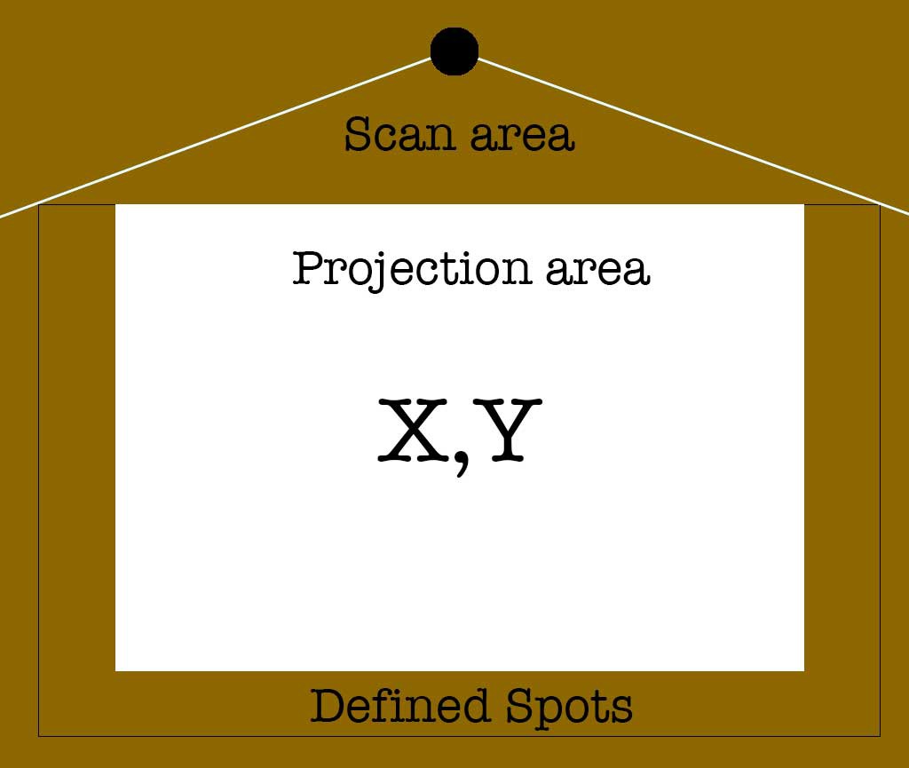
For the inevitable presentation I make a simple plan which shows all the physical properties of all scenarios. It is a simple picture that is meant to focus on what is needed.
![]()
The scan area simple represents the area from which data is acquired. The projection area is of course the image which the interaction with the system is displayed on and this can be interacted with via screen coordinated, however it could also hold defined spots.
The outer boundary could also use coordinates, but most likely will use pre-defined locations that trigger the running application. Point is, these are different applications.
-
LiDAR as HID or trigger
09/26/2021 at 14:53 • 0 commentsThe typical use case for these sensors are robots which are not stationary. I intend to have the sensor stationary and scan a certain area for activity. This activity basically is people standing in the "scan zone". The resulting output depends on the complexity and interactivity needed for the final project.
I'm using the RPLidar project in Python on a RPi4 to process the data and generate the output. I tried getting it to with in CPython, but apparently the current library does not play nice with the current firmware on the censor.
The first task was to understand the data coming out of the sensor and into python. Basically, the sensor provides a dump of measurements every rotation. You get an angle and a distance measurement. I can easily do all the necessary processing between packets.
For a single user interface, the process is very simple. Find the nearest measurement. The following step is either to compare that data to a lookup table and see if that position is a trigger, or to convert the data into coordinates which could then be mapped on the projection area as mouse coordinates.
The Python script can also ignore half the measurements which are behind the area. In the final build, a shield behind the sensor will ensure that these angles won't even generate a measurement point because it will block the laser at a distance where it can't resolve the distance.
The script should also ignores distances that are too far away, leaving the maximum time to process the proper data.
LiDAR as an input device
Experiments with using a 2D 360 LiDAR sensor as an input device.