Maximiliano Rojas
-
Subsystem - Arm
12/01/2021 at 21:25 • 0 comments
Design
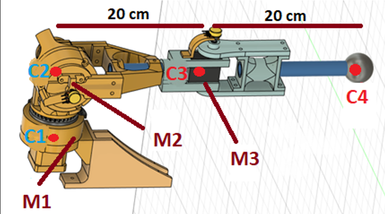
The design of the arm is made in Autodesk's Fusion360 software, which is 40 cm long, where the arm and forearm occupy 20 cm each, the materials for the structures are PVC tubes of 20 mm in diameter and pieces 3D printed. An important aspect is that of the torque that each of the motors must exert, which makes it possible not to move the structure itself and to be able to manipulate objects, by a simple torque analysis it is known that the base motors always (that one in the shoulder) will be the one that exerts the most force per unit of distance at the time by carrying out the movements, for this reason, it was decided to use two NEMA 17 motors with 3D printed cycloidal reducers, while for the elbow a servomotor is simply used, the end effector consists of a clamp with one degree of freedom (open and close). In Figure 1 you can see the complete design.
![]()
Figure 1 - Arms design. As it is the M1 motor that has the highest load in terms of force, it was decided to base the design of the gearbox on it, to include the weight of this element and add a safety factor, the mass of the center C3 was increased to 0.45 kg, while to include the weight of the structure and the hand, a mass of 0.6 kg is selected for the center C4, then the estimated maximum torque is the one calculated in Equation 1.
![]()
As M1 is associated with the stopping torque of the motor, it is necessary to choose a reduction level that makes the magnitude of interest exceed this value, for practical purposes and to eliminate any possibility of failure, a gearbox with a 20: 1 ratio is designed. This generates that at the output of the servomotor a maximum of 80 kg-cm is generated, this criterion is maintained for the rest of the motors, which leaves a margin of ideally 0.725 kg-cm to lift objects at a distance of 40 cm from the motor M1.
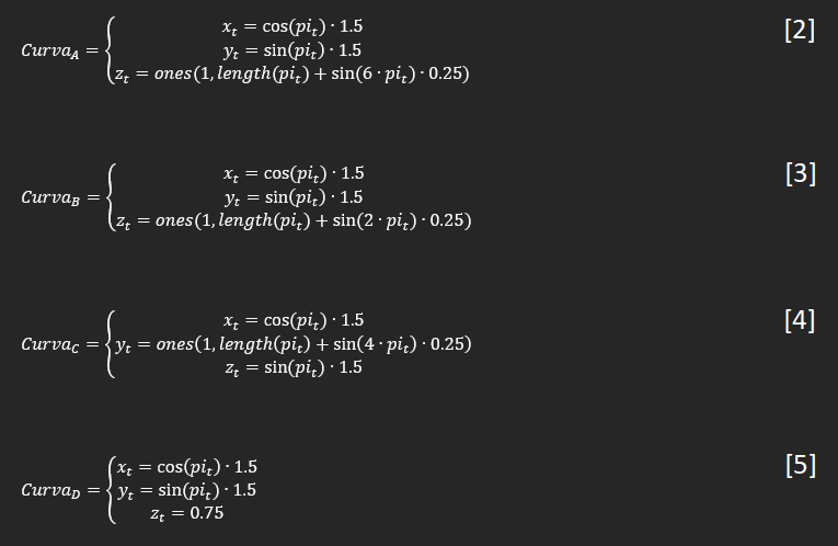
Concerning the control part, it is possible to implement the FABRIK algorithm correctly in MATLAB (code in github), to test the ability to generate spatially and temporally coherent movements, that is, that there are no large angular differences in the space of arm configurations that at each moment is established, the end effector is made to follow a series of points belonging to a pure or deformed circumferential curve in the generated 3D space. The parametric curves can be seen in Equations 2, 3, 4, and 5.
![]()
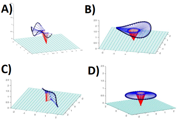
The results are shown in Figure 2.
![]()
Figure 2 - Matlab plots. Regarding the control of the arms, it can be said that the NEMA motors move by angular step control, that is, an H bridge sends signals so the motor moves 1.8 degrees per step in a certain direction until it reaches the desired angular position, proportional control is not applied directly, since the speed of the NEMA motor will vary depending on the error, this would generate a series of problems in the torque made because it is dependent on the angular speed, for this reason, the speed is left fixed and only steps are performed for the control, as regards the elbow, it uses a servomotor which already has a proportional position control in its chip, so it only needs to be given the desired angle in PWM format through a digital output of the Arduino.
Regarding the electronics itself, it should be known that each control signal is made by an Arduino mega independent of the one in the base, this configuration is preferred since it facilitates the task of separating the torso from the base, in addition, the amount of digital inputs and outputs required makes the addition of one of these microcontrollers imperative, each NEMA motor consumes a theoretical maximum of 1.2 A per phase with square signals of 5 V amplitude, which are controlled with an H-bridge whose output maximum continuous current per phase is 2 A, the difference in power between the maximum and that consumed by the actuators is sufficient so that no additional cooling is needed. To measure the angular positions of each of the degrees of freedom, a series of potentiometers are used that are fed by a buck reducer as well as the associated servo motors.
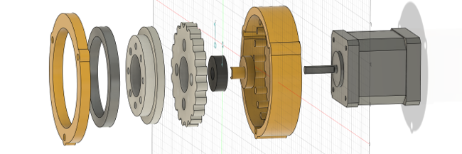
Naturally, the NEMA motor cannot exert the necessary amount of torque by itself, for this reason, the use of mechanical speed reducers is necessary, for budget reasons and ease of prototyping, it is decided to use a cycloidal reducer printed in PLA with a 3D printer. As it must have a reduction of 20: 1, it is immediately known that the number of lobes the internal gear of the reducer must be 21, therefore the external achievements must be 20, as the equations of the profile that it must have are already known, the operation of this type of mechanism can be implemented with a curve in Matlab and exported in SVG format to Fusion360 and then finish designing the rest of the pieces, the complete model can be seen in Figure 3.
![]()
Figure 3 - NEMA with cycloidal reducer.
Fabrik modification
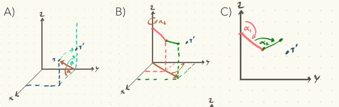
FABRIK is not designed for robotic mechanisms, therefore, it is necessary to implement a series of modifications to be able to restrict the movement of each of the degrees of freedom of the arm.Although the author [1] proposes a series of limitations through the projection of cones or the generation of planes in 3D space, he does not specify in detail how to apply each of these, even becoming somewhat confusing. Given the structure that is proposed in this work, it is possible to make a much simpler and equally efficient modification, which consists in limiting the development of the algorithm in a 2D plane, to achieve this, a rotation of the objective point is made along from the x-axis to bring it to the ZY plane (Figure 4A), and so that FABRIK does not move the joints freely, a translation of the positions of the vectors representing the arm is made towards the same plane (Figure 4B), in this way a 2D FABRIK remains (Figure 4C).
![]()
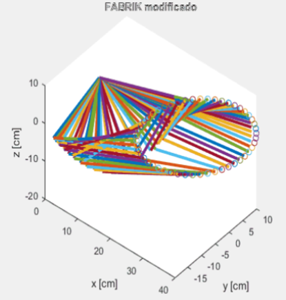
Figure 4 - Fabrik's input modification. To check that no erratic behavior is generated by the modifications to the original algorithm in matlab, a lopsided ellipse in a 3D Cartesian space is entered as target points, the result can be seen in Figure 5.
![]()
Figure 5 - Matlab test. So if the entire algorithm process is done in 2D space, how can it be possible that the result is still in 3D space? This is achieved because once the angles of the degrees of freedom corresponding to the y-axis have been found, both the target and the vectors representing the arm are performed an inverse rotation, in this way both these points and the angles leading to the target point can be obtained.
ROS integration and signal filtering
As is well known, it is an Arduino Mega that carries out the control commands for the different servo-actuated motors, therefore, it is necessary to implement an interface between it and the Jetson Nano, thanks to the use of ROS this can be easily implemented through the Rosserial package, which enables the microcontroller to generate nodes to publish or receive the data through topics.
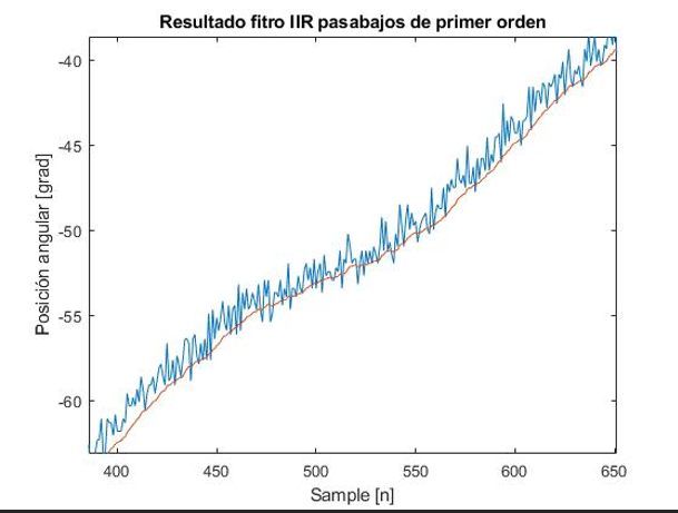
With all the elements implemented and programmed, a movement test is carried out, which presents problems because the potentiometer that measures the angular position has a noise level large enough to generate errors in the closed-loop control, this is solved by implementing a first-order low-pass digital IIR filter, in Figure 6 you can see the noisy signal in blue and the filtered signal in red.
![]()
Figure 6 - Results of the low-pass filter IIR. Where the difference equation used is:
![]()
-
Subsystem - Mobile base
09/27/2021 at 09:45 • 0 commentsHi guys, in this log I intend to explain a little bit how the mobile platform works, so as usual this subsystem will be divided into two main topics: hardware and software, but before that lets see a video!
Software
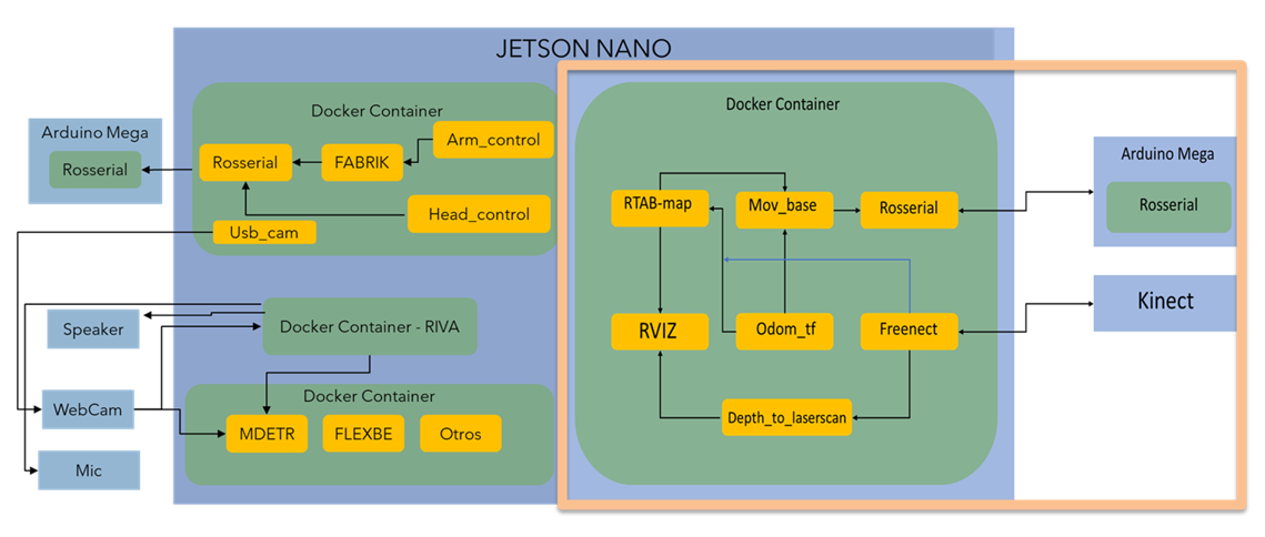
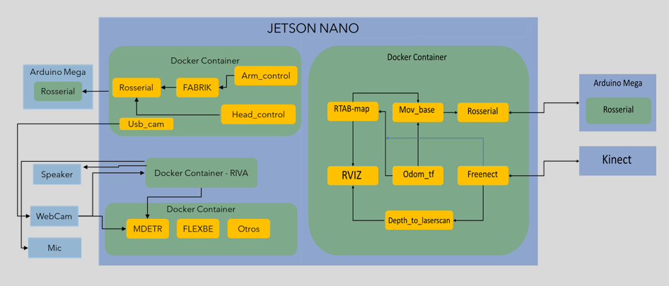
One of the main concepts in the whole process of this robot design is modularity, for this reason, I think ROS is a good choice, with this meta operative system you can easily create programs and interconnect them, basically, it establishes a solid way to create complex robotic systems with not only a high degree of personalization but also its wiki provides a large amount of documentation and ready-to-go packages of programs, a good characteristic to fastenest the prototype development process, of course, ROS by itself can be very confusing and tangled when the projects become big enough and that's why I decided to use docker with it, containers allow me to separate the software in different groups that can communicate between them (a nice trick is to configure them to connect to the host network so no multimachine ROS parameters assignment are necessary), in the light orange square of the Figure 1 you can see the general and simplified structure of the docker-ROS:
![]()
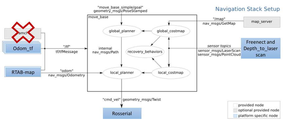
Figure 1 - General software configuration. Let's briefly summarise what all the navigation nodes do and how they work together:
- Rosserial: This a ROS package provided for the community that allows the computer to communicate easily with some microcontrollers development boards such as Arduino and Esp8226, the microcontroller can be a node with a very similar structure with a c++ one, and there are enough messages types to prototype[1].
- Freenect: This is another ROS package that provides all the necessary files to connect a PC with a Kinect V1, when is launched it provides several topics with RGB, cloud point, registered point cloud, and tilt control messages (between others) basically with this I can obtain the necessary data to create the navigation maps[2}.
- Depth_to_laserscan: As its name says this package simulates a laser scan sensor (like a lidar) from the depth cloud map from the, in this case, the Kinect V1, a necessary part because this message type (laserscan) is necessary to create a 2D grid map[3].
- Odom_tf: This is just a custom made node that connects the reference frame of the Kinect V1 with the reference frame of the mobile robot, this is important because the general system needs to know where the camera is positioned to adequate the position of the cloud points in the representation of the real world [4].
- Mov_base: It provides the implementation of the actions to control the robot mobile base in the real world given a goal in it, it has global and local maps and planners to modify the mobile base behavior to the grid map and the local objects that can suddenly appear, at first it can be a little tricky to make it works with all the other packages (at least for me), so in [5] you can read more about it in a more comprehensive way.
- RTAB-map: This is a ROS wrapper of the Real-Time Appearance-Based Mapping algorithm, basically it is a visual RGB-D SLAM implementation for ROS, which means the robot can generate a 3D map of the environment and through a global loop closure detector with real-time constraints, it can know where the robot is in the map, more information in [6].
- RVIZ: This is a 3D visualization tool for ROS and is used to see all the sensor information and how the packages make sense of it in a visual way [7].
In the Figure 2 you can see how all of these packages send information to others in a more ROS-like way.
![]()
Figure 2 - How Packages works together.
All the implemented nodes in the Navigation Sack are in the mov_base package, but to make it work properly is necessary to configure some parameters, there is a bast list of them so in order to understand its role in the system you must know that to navigate the robot create three maps:- Occupancy map, where all the static elements of the environment are represented.
- Global cost map, based on the first one, here an area around the objects are generated to "tell" to the global path planning to not make movements there, so the robot is safer from hitting anything.
- Local cost map, like the previous one, but in this case, the safe area are generated in "real-time" around a certain radius from the robot, its purpose is to avoid local dynamic objects, like a dog, or your grandmother moving around.
There are configurations that affect both maps, and those are:
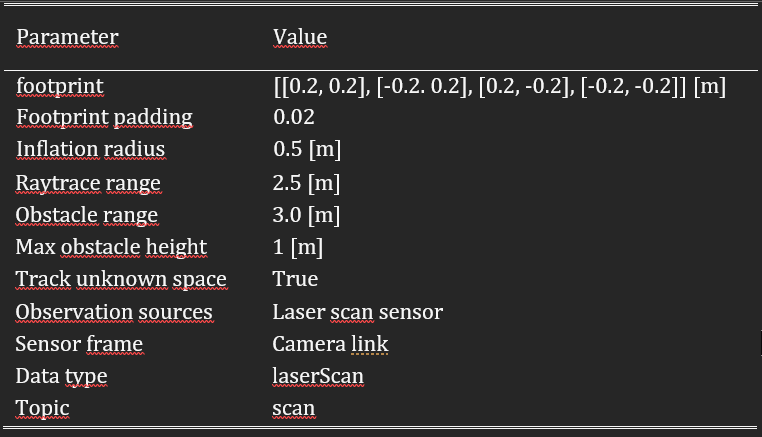
- Obstacle_range: maximum rango to detect objects in meters.
- Raytrace_rangel: maximum range detection of free space around the robot.
- Footprint: coordinates in meters that contain the base's area of the robot.
- Footprint_inflation: Safe area around the robot.
- Inflation_radius: maximum distance of an obstacle to generating a safety area.
- Max_obstavle_heigh.
- Min_obstacle_heigh.
- Observation_sources: these are the list of sensors and their characteristics used to generate the maps.
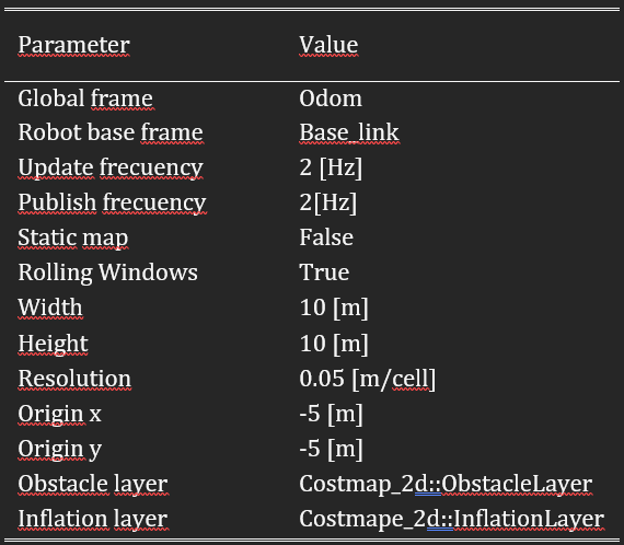
The parameters that affect the global cost map are:
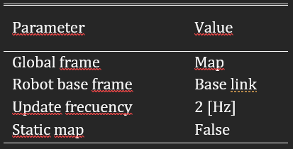
- Global_frame: it defines the vectorial space (coordinate system) that is used for the maps.
- Robot_base_frame: reference frame for the maps that specify the pose of the robot's base.
- Update_frecuency: map's update frecuency in hertz.
- static_map: it tells if the cost maps must be loaded or not based on the previous ones (if there are any).
The parameters that affect the local cost map are:
- Rolling_window: indicate if the local map keeps its relative position in the center of the robot or not.
- Width: width of the map in meters.
- Height: height of the map in meters.
- Resolution: meters per grid.
- Origen_x: map's origin coordinate x.
- Origen_y: map's origin coordinate y.
- Obstacke_layer: the layer of the map with the obstacles.
- Inflation_layer: the layer of the map with the safety areas.
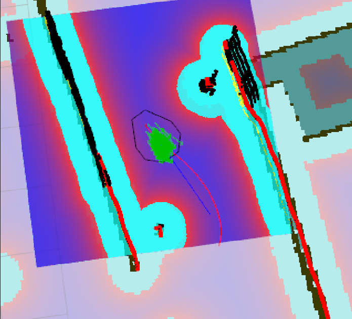
In Figure 3 you can appreciate the global cost map in light blue, the local cost map in the purple area, and the occupancy map as all the ground in grey, and all the objects in black.
![]()
Figure 3 - Maps of the navigation system.
The values that I used are:![]()
Table 1 - Common parameters. ![]()
Table 2 - Local cost map parameters. ![]()
Table 3 - Global cost map parameters. Hardware
Here three topics are presented, the CAD model, the 3D print parts, and the electronics, for the first one I must say that all the modeling was made with Fusion360 (student license, although there is a free license with like one year of use).
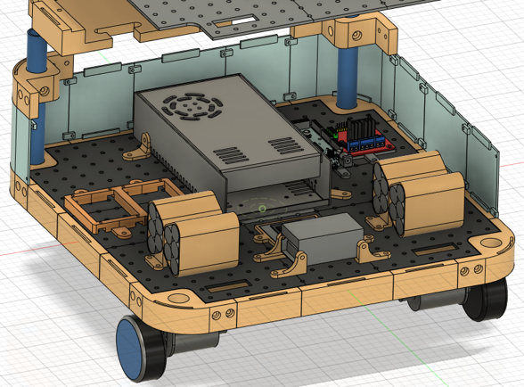
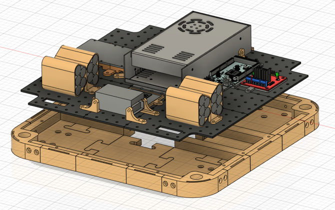
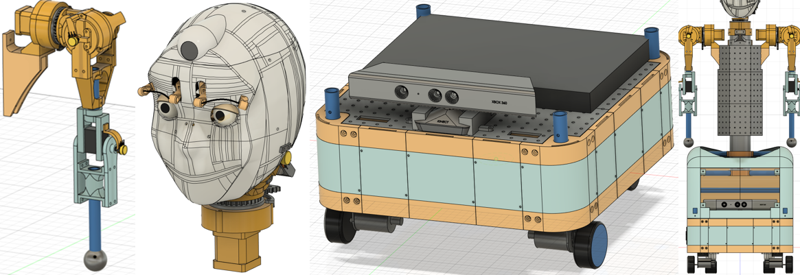
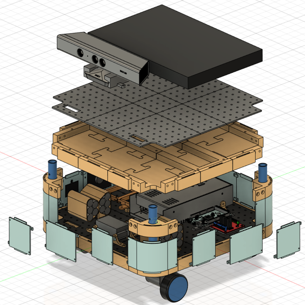
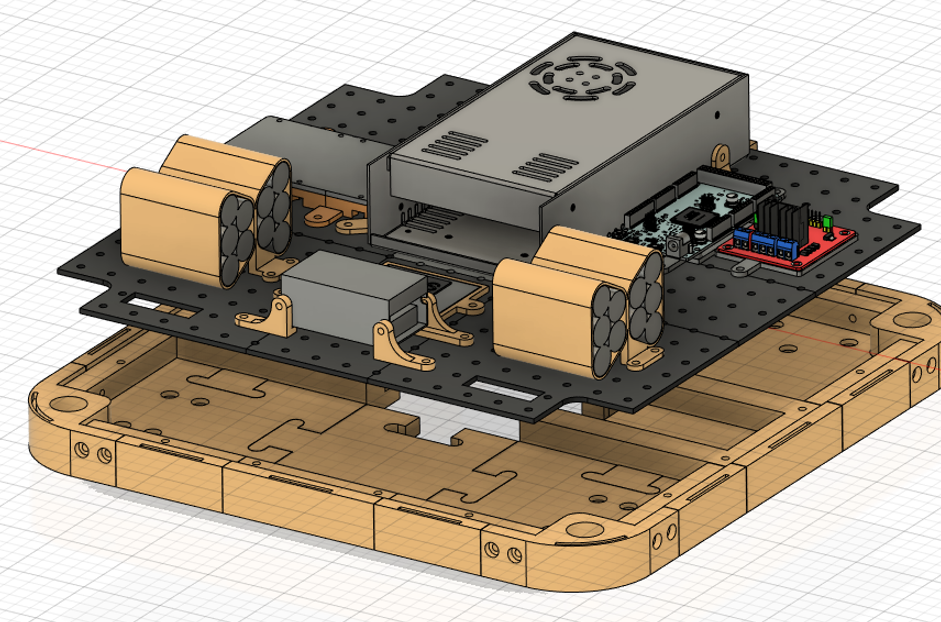
I want it to be easy to modify for others, that's why I designed the base with various interchangeable parts, so if you want to add some feature that needs to put something in the case, the process shouldn't be a headache, similarly, all the electronics are attached in platform with a pattern of holes for the same reasons, in the Figures 4, 5, 6 and 7 you can see the 3D model representing all of this.
![]()
Figure 4 - Parts of the mobile base. ![]()
Figure 5 - Perspective of the inner parts of the mobile base. ![]()
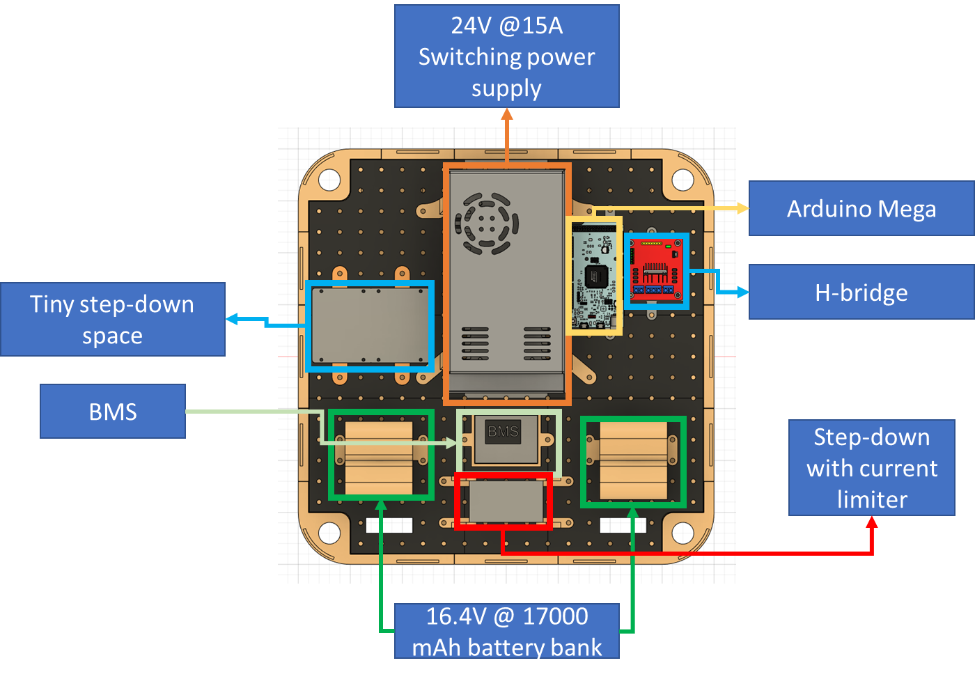
Figure 6 - Electronics attached to the platform with holes. ![]()
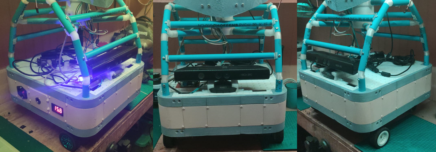
Figure 7 - Electronics parts of the mobile base. In Figure 8 you can see how it looks in real life.
![]()
Figure 8 - The result of the mobile base.
As regards electronics there are several considerations to take, in the mobile base are all the main components for energy regulation and distribution to all the components in the rest of the robot, to accomplish this task a battery bank with 16.4V @17000 mAh is made from 20 NCR18650 wichs allows approximately one and a half-hour of autonomy, these batteries has a recharge cycle and the manufacturer [8] recommends a current of the 0.5 times the capacity of the battery, if you observed the Figure 6 there are two components to accomplish that, the BMS regulate the charge of a set of 4 NCR18650 per stage by voltage levels and the step-down based in the XL4016 [9] limits the current along the way with the voltage to the maximum allowed for the BMS, which is 16.8V [10].A lot of elements need different levels of voltage to work, for example, one sensor works with 3V3 meanwhile the other needs 5V, one type of regulation that can be useful can be based on the LM78XX series [11] because it can have an output between 5V to 24V (depends on the model), and although they can keep a 4% of output tolerance and has overcharge protection they use is very limited to the 1A of supported current to the load, another good option can use Buck's modules based on the LM2596S [12] which is synchronous converter at 400 kHz with an output range of 1.2V to 34V (4% tolerance as well) with constant 3A, the power dissipation is internally regulated and generally is very efficient (even with the generated heat).
References[1] http://wiki.ros.org/rosserial
[2] http://wiki.ros.org/freenect_launch
[3] http://wiki.ros.org/depthimage_to_laserscan
[5] http://wiki.ros.org/move_base
[6] http://wiki.ros.org/rtabmap_ros[7] https://github.com/ros-visualization/rviz
[8] https://www.batteryspace.com/prod-specs/NCR18650B.pdf[9] http://www.xlsemi.com/datasheet/XL4016%20datasheet.pdf
[10] https://www.mantech.co.za/datasheets/products/BMS-40A-4S_SGT.pdf
[11] https://www.mouser.com/datasheet/2/149/LM7812-461970.pdf
-
Introduction - A general overview
09/27/2021 at 08:24 • 0 commentsAs I said in the description, Aina is an open-source humanoid robot which aim is to be able to interact not only with its environment in terms of moving through it and grasp some light things but also speak and interact with humans by voice and facial expressions. There are several tasks that this robot can accomplish once it's finished like:
- Assistance: Interaction to assist, for example, elders, students, and office workers through remembering events, looking for unusual circumstances in the home, between others
- Development: Aina is also a modular platform to test algorithms of robotics and deep learning.
- Hosting: It can guide people in different situations and places to inform, help, or even entertain someone.
These tasks by no means are far from reality, a good example of it is the pepper robot, used in banks, hotels, and even houses., so let think about which characteristic the robot must have to do similar things:
- Navigation: It must be able to move through the environment.
- Facial expressions: It must have a good-looking face with enough set of emotions.
- Modularity: Easy to modify the software and hardware.
- Recognition: Of objects with Deep Learning techniques.
- Socialization: Be able to talk like a chatbot.
- Open source: Based on open-source elements as much as possible.
Because there is a lot to do a good strategy is divide to conquer, for this reason, the project is separated into three main subsystems and a minor one:
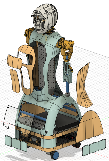
- Head: this is part that enables the emotional side of the communication through facial expressions with the eyes and eyebrows (and sometimes the neck), no mouth is added because I think that the noise of it moving can be annoying when the robot talks.
- Arms: No much to say, the arms are designed in an anthropological way and due to financial constraints this cant can have high torque, but I can it move with some NEMA 14 with 3d printed cycloidal gear to gesticulate and grasp very light things, so it's fine.
- Mobile base: This is the part that enables the robot to map, position it, and move the robot in the world through a visual slam with a Kinect V1.
- Torso: As the middle part that interconnects the other subsystems.
![]()
The general characteristics of the robot are:
- A mobile base of area 40x40 cm2.
- Total height of 1.2 meters.
- A battery bank of 16.4@17000 mAh.
- estimated autonomy of one and a half hours.
- It has spaces for modularity, which means that it's easy to adapt it to future necessities.
- The arms has 3 degrees of freedom each one and three more in the hand.
- The software is based on ROS and docker, so it's faster and easy to develop.
- Part of its behavior is based on deep learning techniques.
Several parts of the robot has holes or are detachable and even interchangeable, the holes are useful to attach electronic components to the robot keeping the possibility to remove them (or add others) whenever necessary, meanwhile, the detachable parts can be modified to fulfill future requirements, like add a sensor, a screen or just make room for more internal functionalities, a good example of this is the mobile base, as you can see in the next images there are several parts that others can modify (light blue ones), and if you want to move or exchange some electronic part just unscrew it.
![]()
![]()
Of course, the same principle applied to the rest of the robot.![]()
In regards to the software, as I said before is ROS and docker based, the simplified scheme of connections between the different elements are presented in the next image.
![]()
As you can see several containers are running on a Jetson Nano, let me clarify the purpose of them, the docker container on the right part is responsible for the navigation task, it's able to do the whole slam process with a Kinect V1 and control the non-holonomic mobile base to the goal point specified by the user, the yellow squares represent the ROS packages implemented to accomplish the task, the up-left docker container has all the necessary programs to control the head, neck, and arms, to find the right angles for the last one a heuristic inverse kinematic algorithm called FABRIK is implemented as a node (you can have my Matlab implementation in the file section), the middle-left containers has all the necessary files to run the SDK conversational AI provided by Nvidia called RIVA (is free and there is any license trouble to be used in non-commercial open-source projects), it has more capabilities like gaze and emotion detection, that will be very useful for the social interaction part, the las container (down-left) has a neural network model called MDETR wich is an multiomodal understanding model based in images and plain text to detect objects in images, FLEXBE is a ROS tool to imeplemente state machines or behavior schemes in a firendly graphical way, so it can be said that this containers is about the "reasonong and behaviur part" of the social interaction.
That's it for now, in the next logs more details will be presented.
[2021] Aina - Humanoid plataform ROS robot
Aina is an open-source social robot that's able to speak and move with nearly no human intervention based in ROS that has AI inbuilt.