 kmatch98
-
1Braiding mechanism components
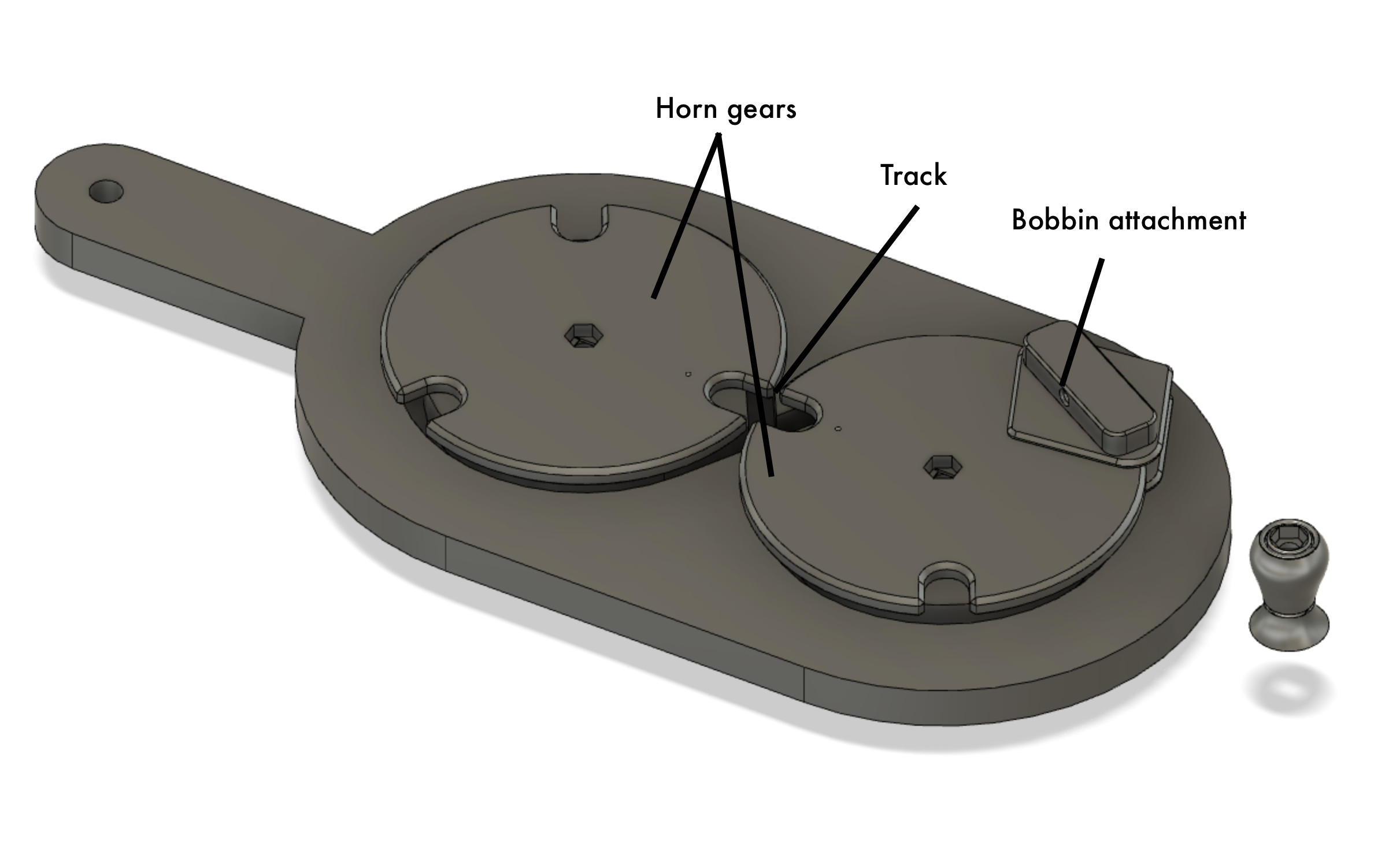
The main components of the braiding machine are shown in the diagrams below.
![]()
Top view showing horn gears.
![]()
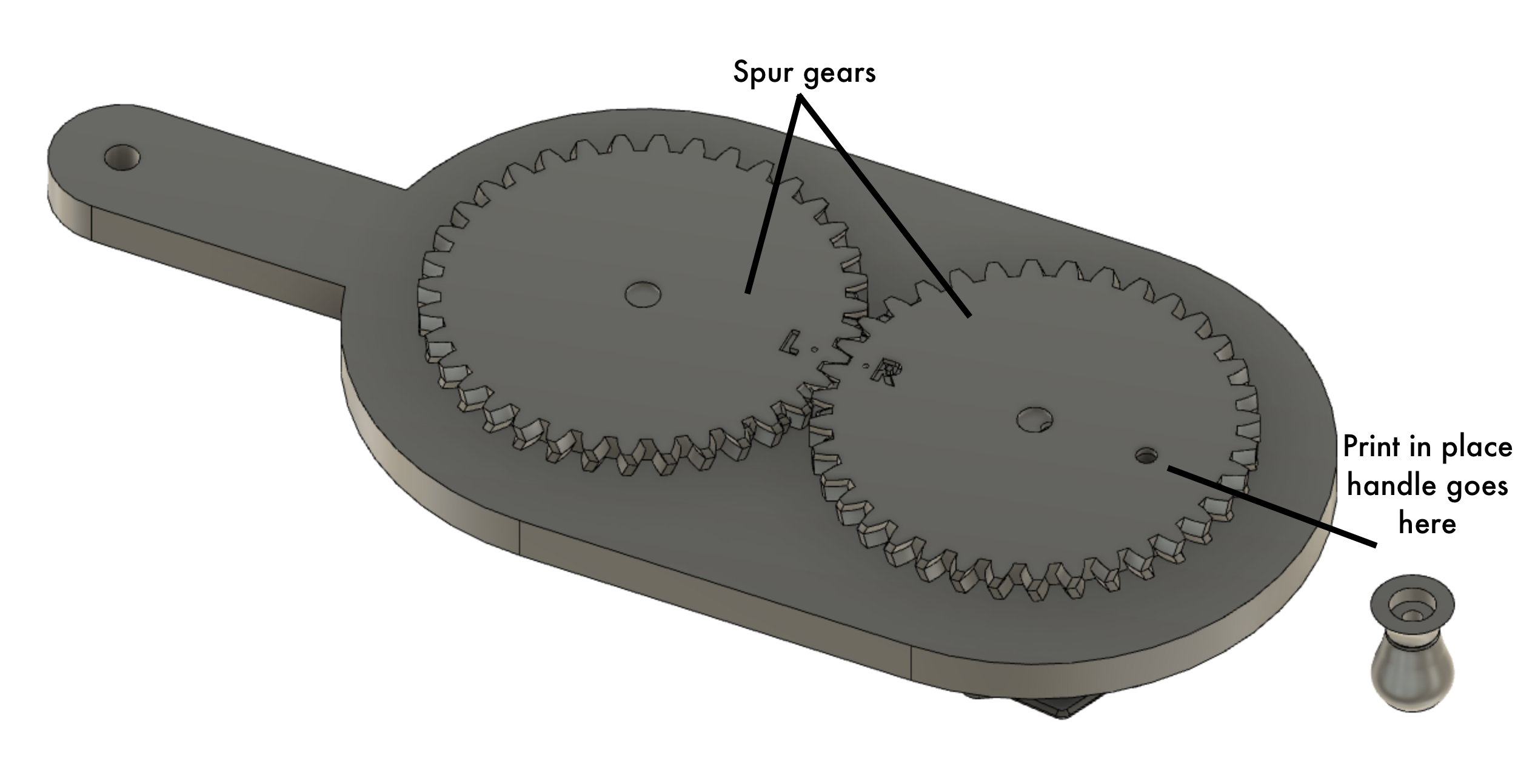
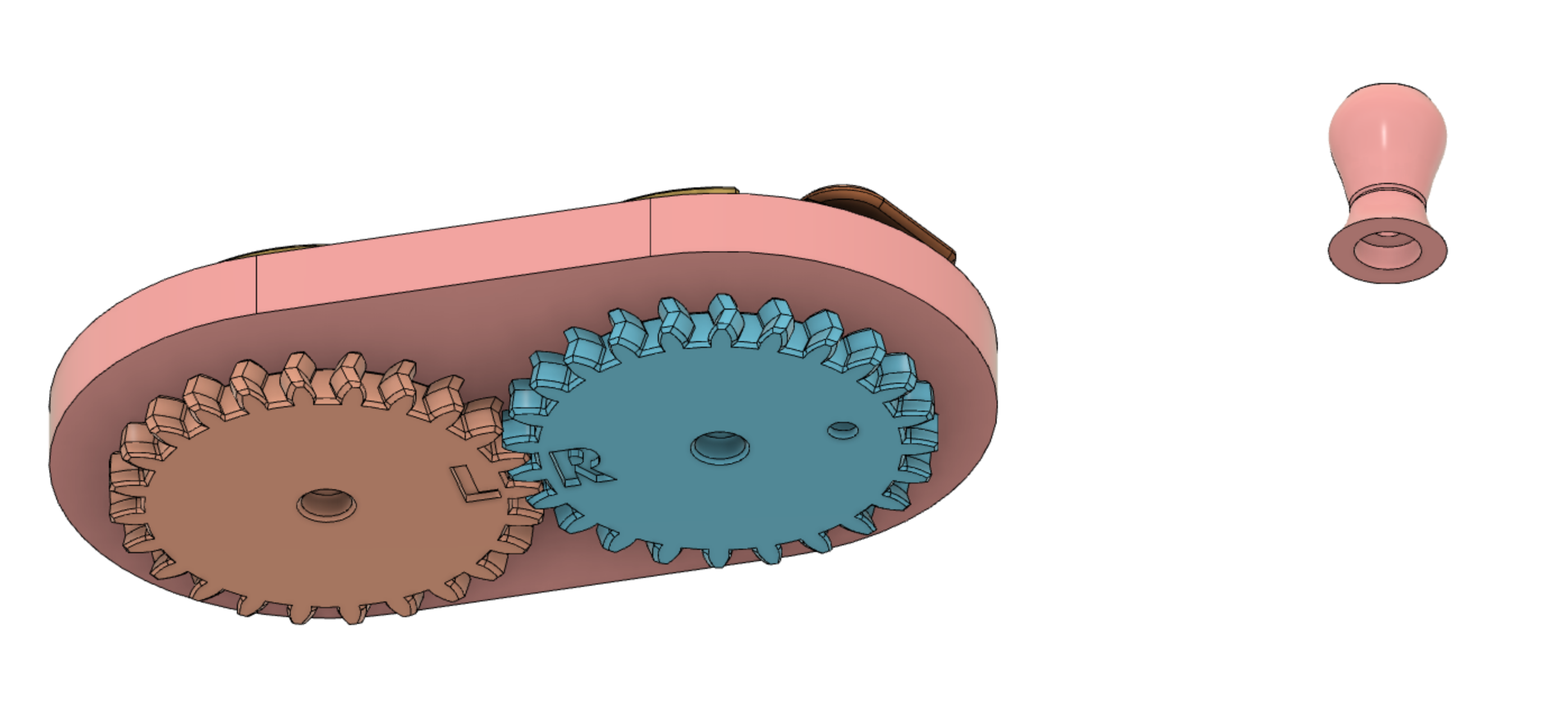
Bottom view showing spur gears and location for attaching the print-in-place handle.
![]()
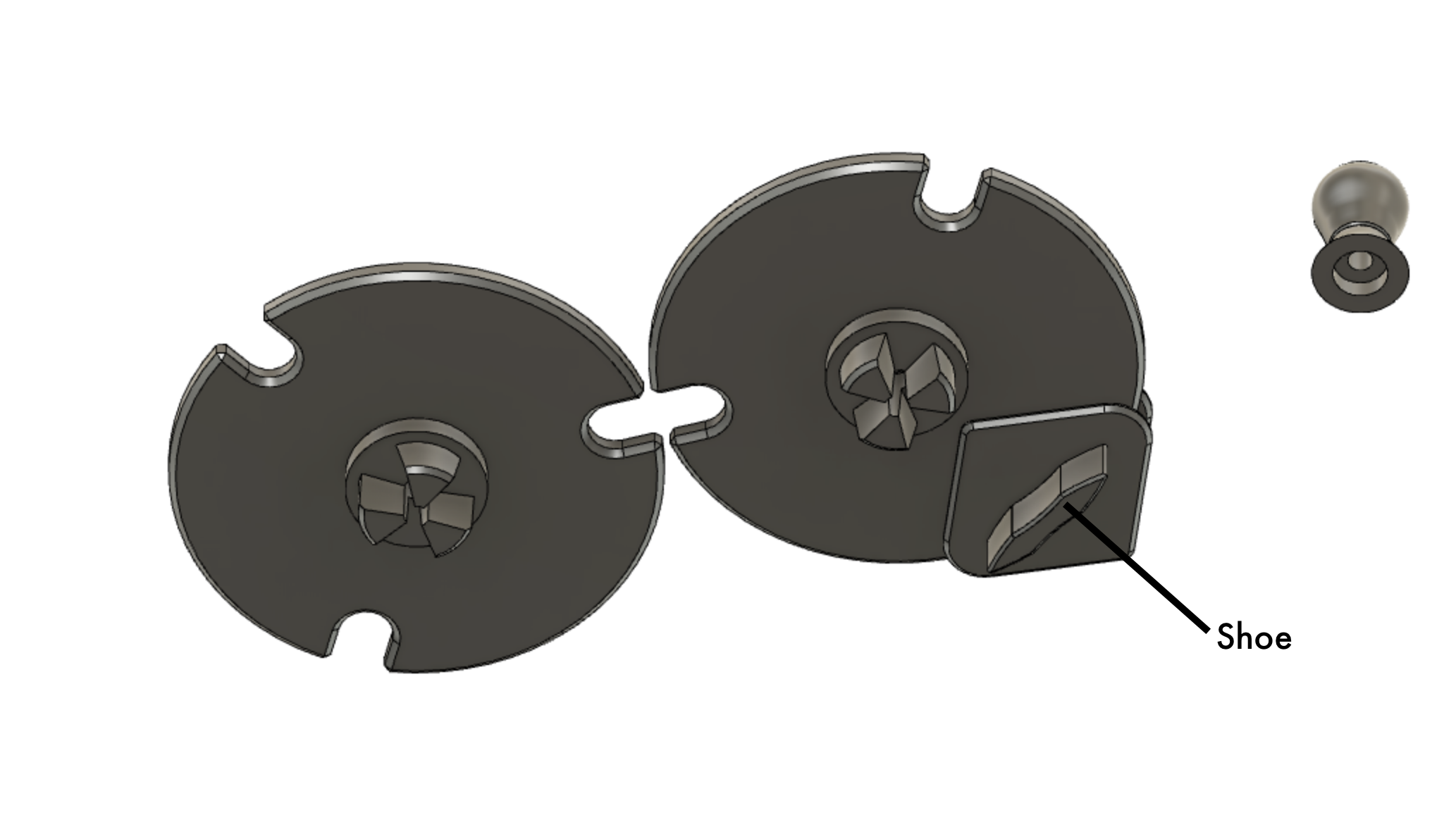
Underside view of horn gears showing the horn gear shafts and the "shoe" that slides in the track.
![]()
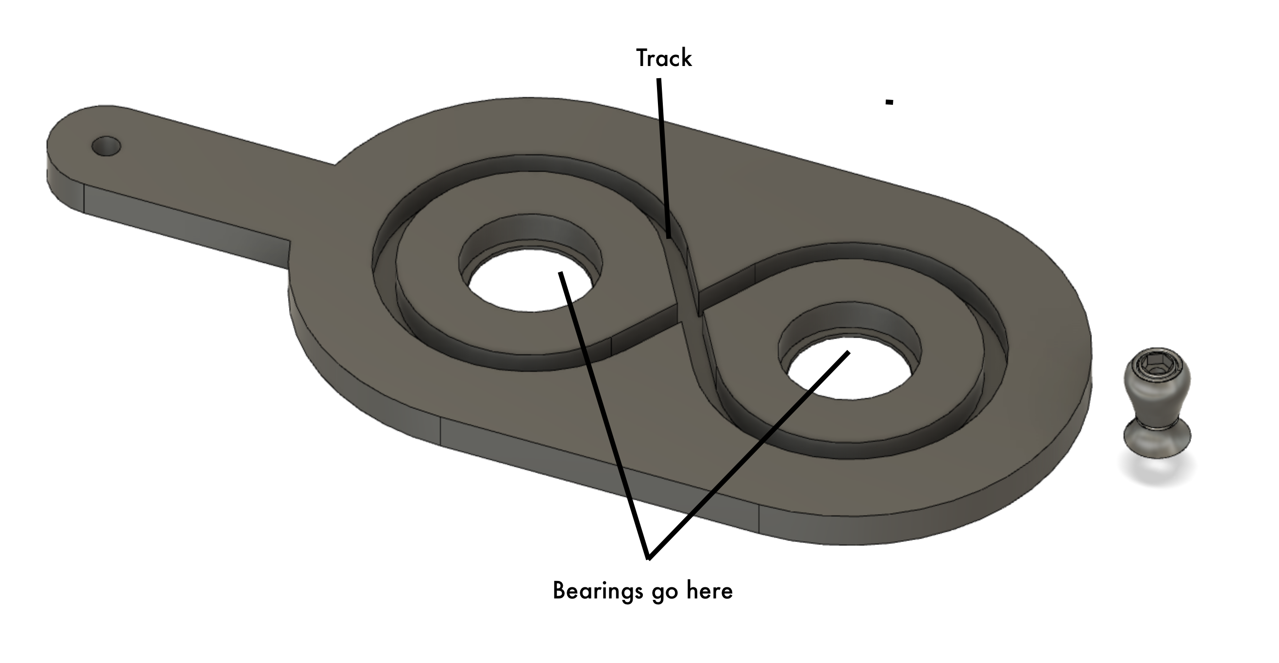
View of the track and bearing holders.
![]()
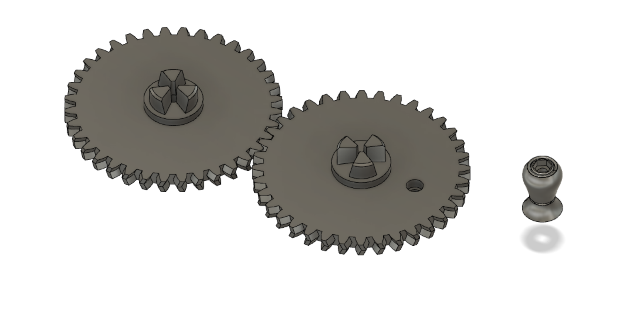
Top view of just the spur gears showing the shafts.
![]()
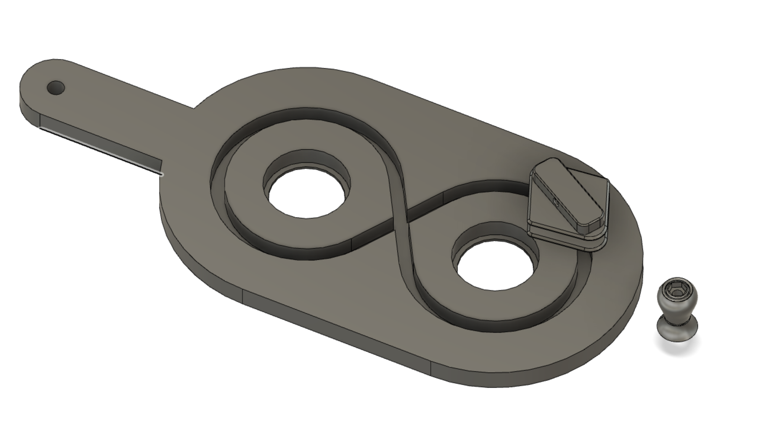
Top view of the bobbin carrier in the track.
![]()
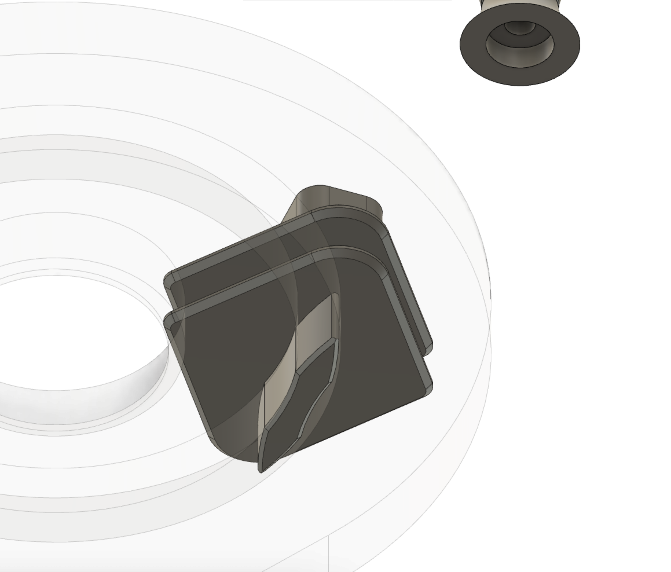
Here's a view with a transparent track showing how the shoe slide along the track.
![]()
-
2Bobbin carrier
The bobbin carrier's function is to:
- Hold the bobbin
- Release yarn from the bobbin
- Maintain constant tension on the yarn while the carrier moves around the tracks
Because the bobbin weaves back and forth around the track, the distance between the bobbin and the braiding point is perpetually changing. To keep an even braid, its desirable to maintain an even tension on the yarn even as it moves on the track.
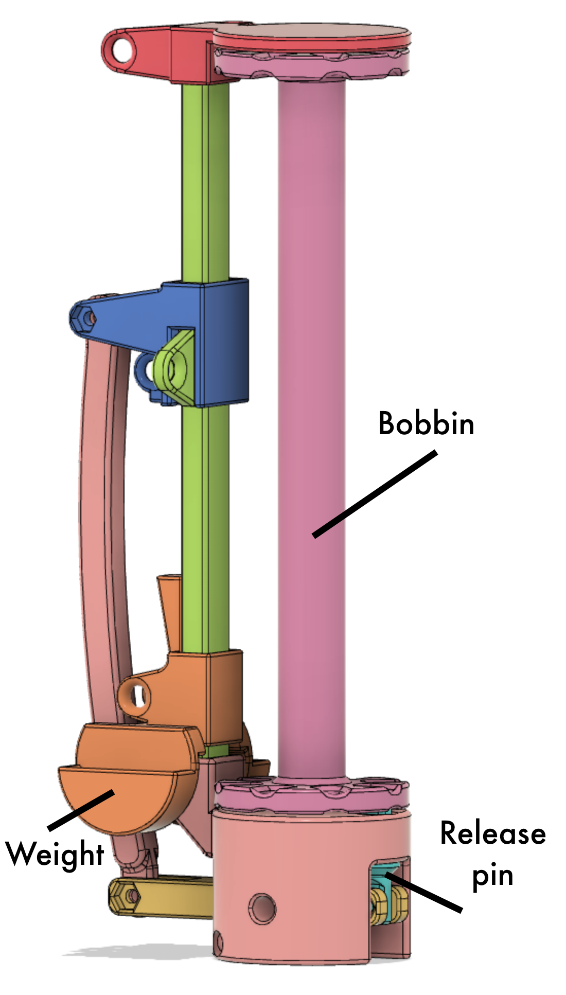
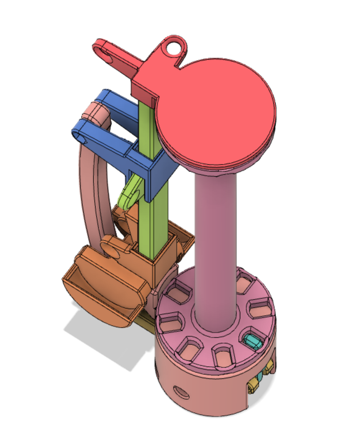
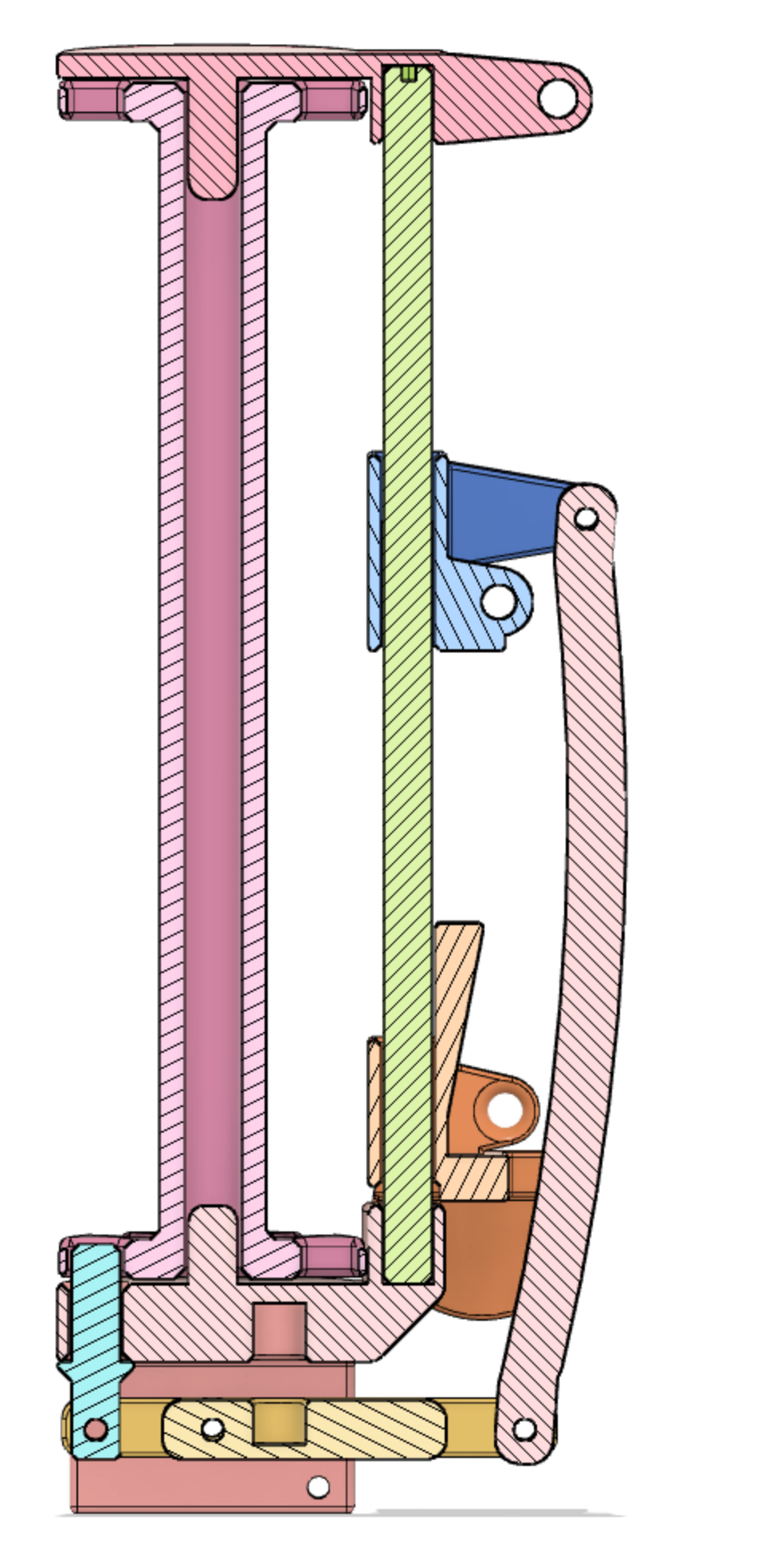
This design of a bobbin has two main mechanism. The first is a gravity tension control. This consists of a weighted platform that slides up and down the vertical bar. This helps maintain constant tension while the distance to and from the braiding point changes. The second is a thread release mechanism. This consists of a slotted bobbin and release pin and a release mechanism. When the tension on the yarn becomes high enough, the tension release the pin and the bobbin spins to release more yarn. Suddenly the tension drops and the release pin recaptures the bobbin. The release tension is controlled by a spring, a release lever and the threading of the yarn through the mechanism.
![]()
![]()
![]()
The slot at the bottom houses the release pin spring.
The weighted orange piece slides up and down on the vertical shaft. When the tension becomes high enough, it pushes up on the blue bracket. This blue bracket pulls the yellow lever through the link, thus releasing the blue release pin. The bobbin then release additional yarn, suddenly the tension drops and the release pin re-engages the bobbin.
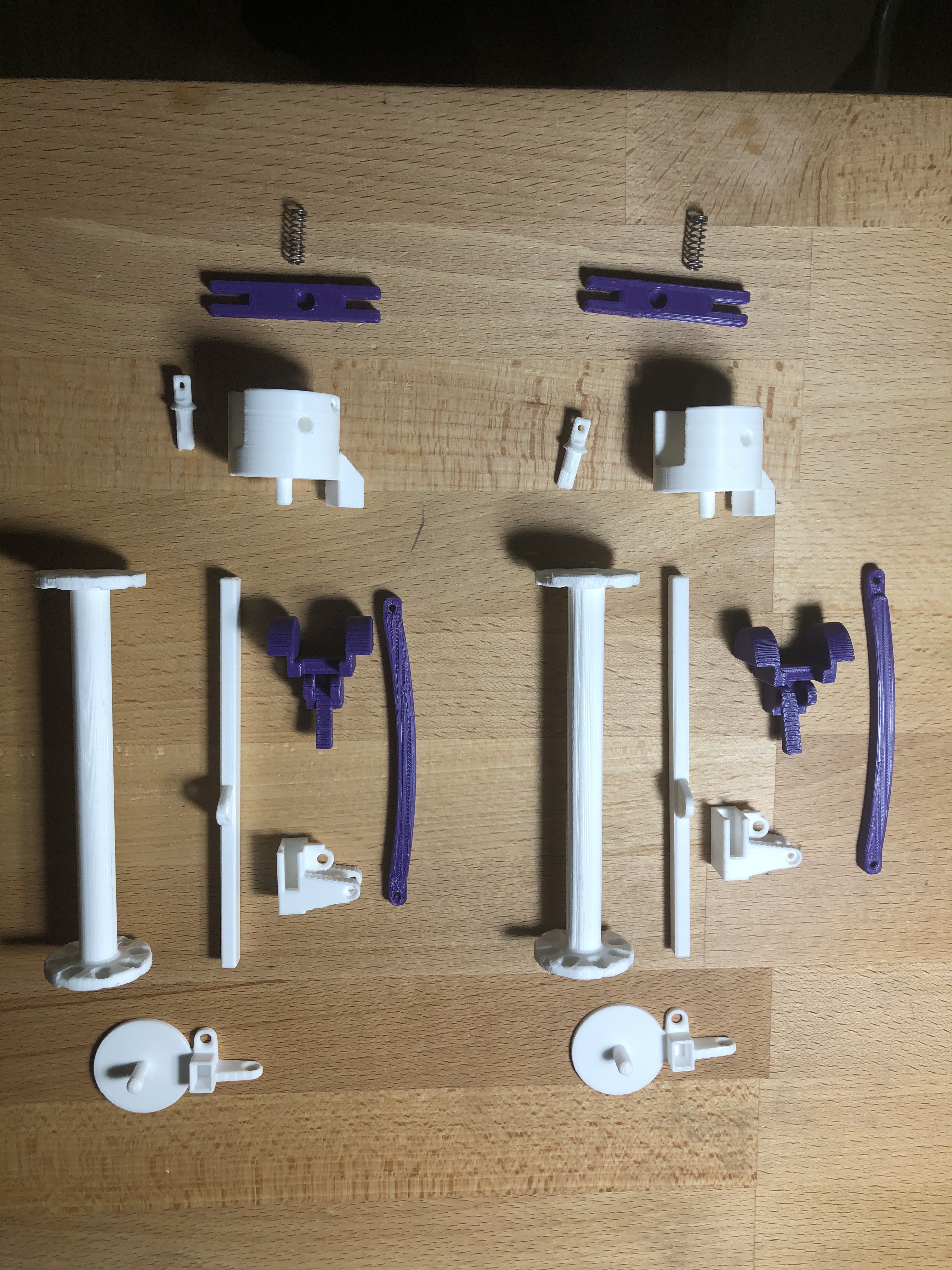
Here are the all the bobbin carrier pieces laid out separately, also showing the spring.
![]()
-
3Bobbin carrier threading
The bobbin carrier must be threaded property to actuate the weight tension mechanism and the release pin.
All directions (right/left) are looking at the back of the actuator link (the white piece)
1. Bobbin yarn goes directly to the bracket opening on the right.
2. Down through the right side weight slot.
3. Up through the bracket (feeding from right to left).
4. Down through the left side weight slot.
5. Up through the final top slot.
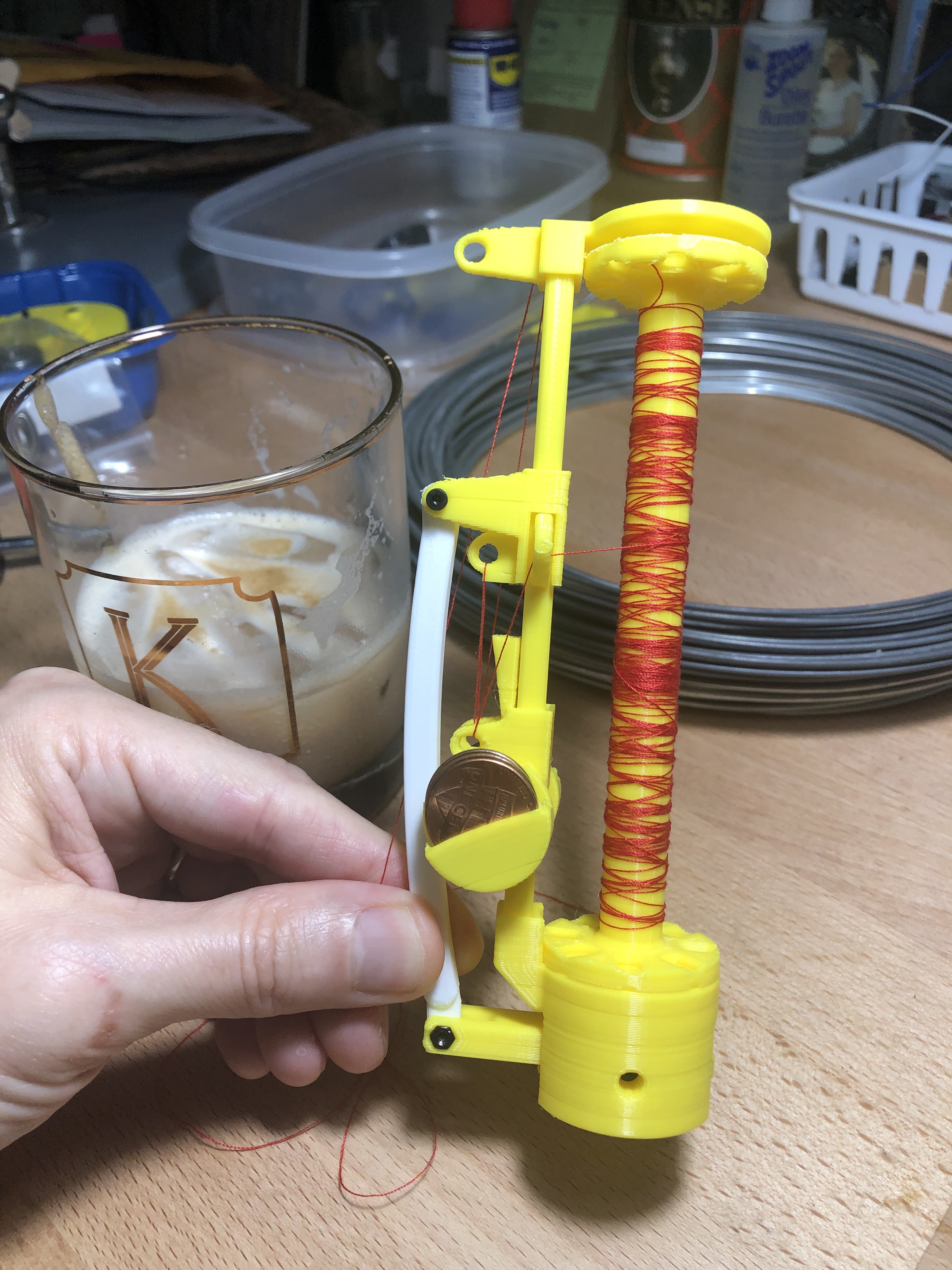
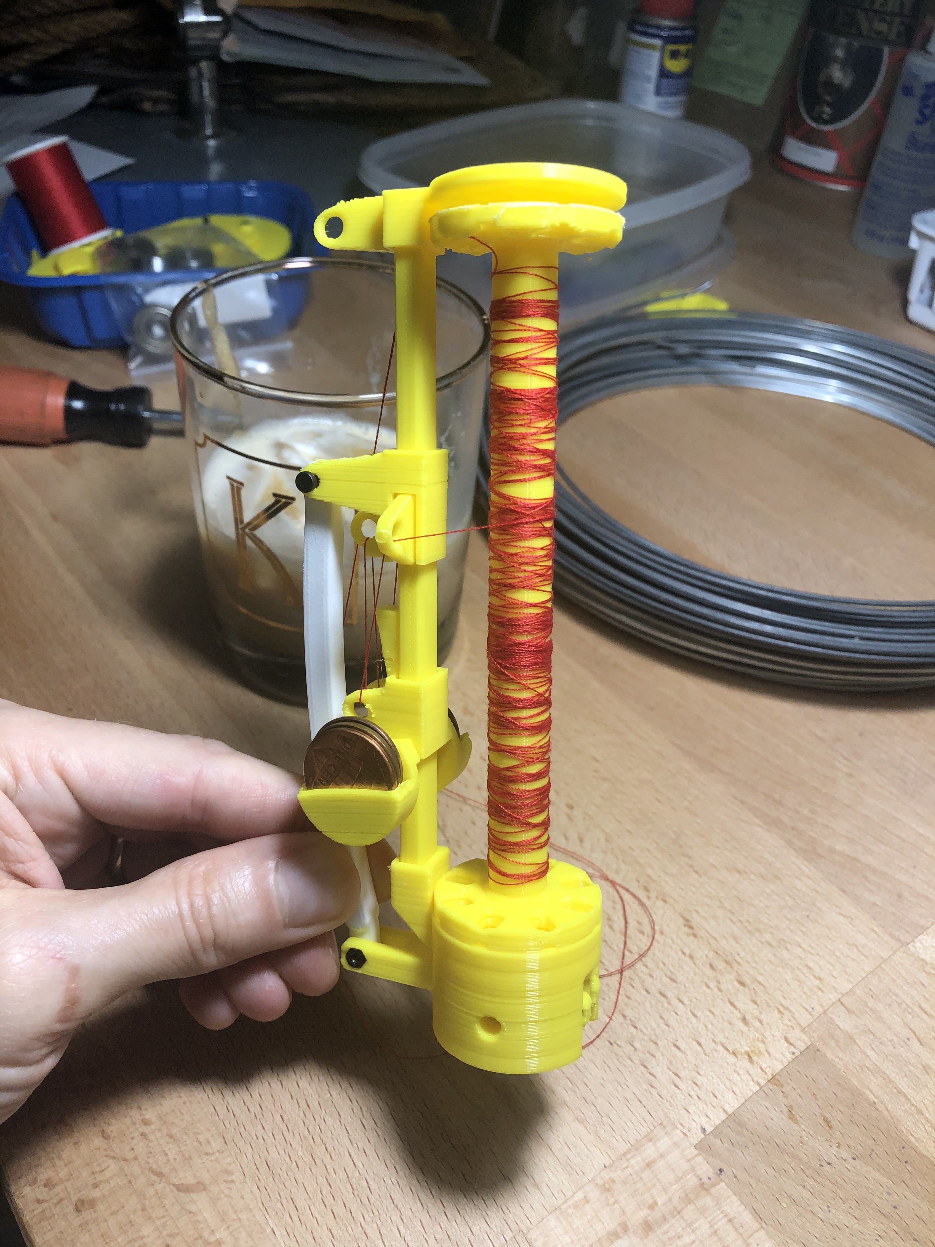
This shows some images of the threaded bobbin carrier, with a Dalgona coffee for scale.
![]()
![]()
![]()
Threading diagram:
Be sure to load the bobbin the correct direction so that the yarn comes off the bobbin in the direction of the first slot.
-
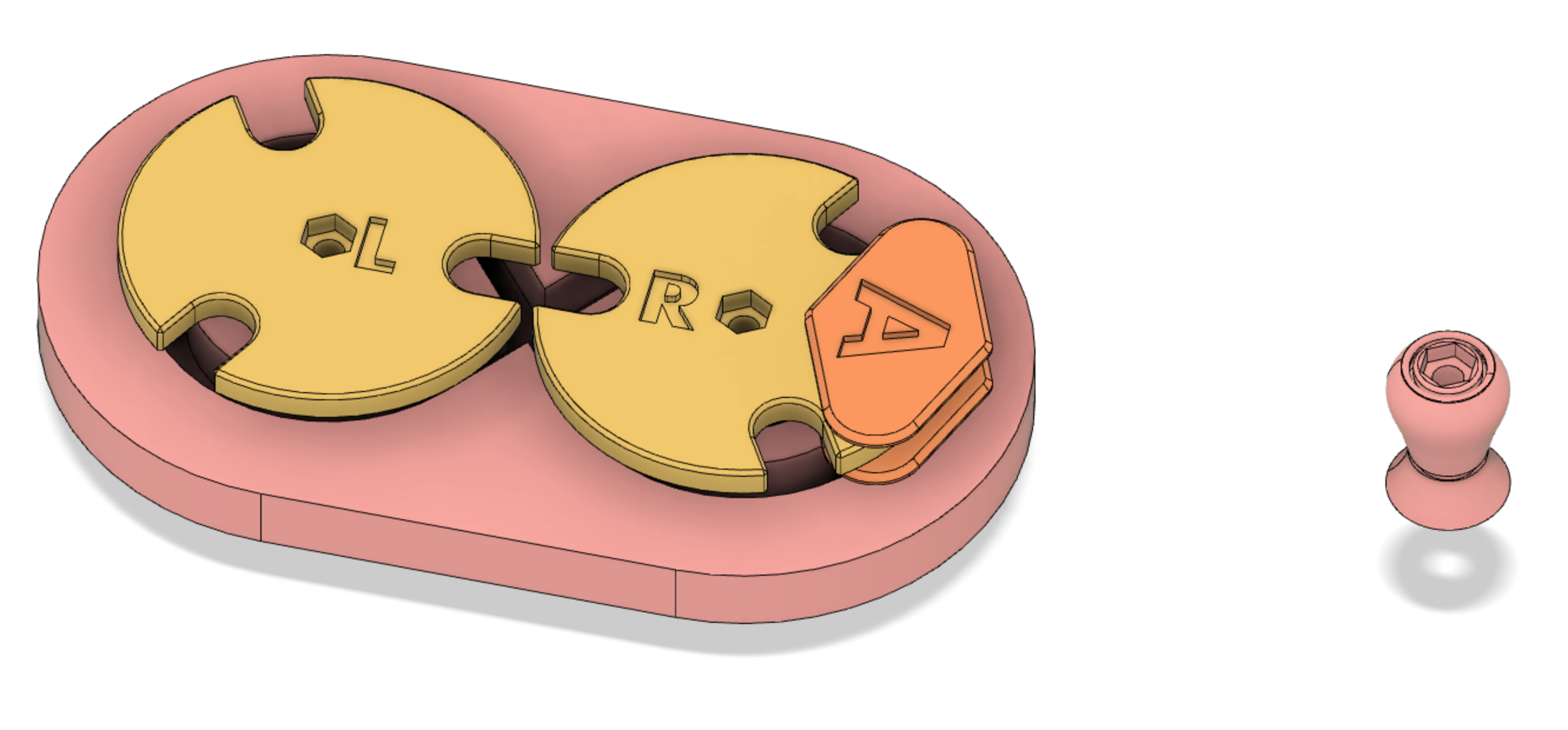
4Fidget toy version
If you want to display the basic mechanism, you can print a smaller version, see the files section.
![]()
![]()
![]()
-
5Take up mechanism
To design a full braider, you will then need to build a take-up mechanism. This is the roller that pulls the finished product through. It should be mechanically linked with the spur gears (or electronically controlled individually).
The speed of the take up wheel versus the speed rotation of the spur gears will affect the finished braid product. and the braiding angle.
Design of the take-up wheel should provide sufficient friction so that the finished braid product does not slip, usually by providing multiple turns of the product around friction two wheels.
The take-up wheel is outside the scope of this project, but look for some examples and I hope you will get the idea.
-
6Other resources and terms to search for
- Braiding Technology for Textiles by Y. Kyosev especially chapter 6 and chapter 7
- commercial high-speed braiding machines
- New England Butt Braiding machines: This uses an older design where the track is on top of the horn gears
- bobbin carriers
Braiding Machine - Maypole Braider and bobbins
Basic design concepts for a 3D printable maypole braiding machine with bobbin carriers designed with tension control.

Discussions
Become a Hackaday.io Member
Create an account to leave a comment. Already have an account? Log In.