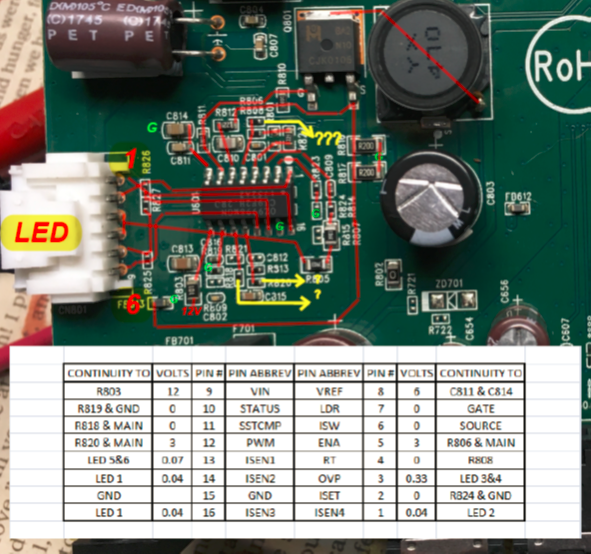
Used continuity for above trace paths, where pens 1,14,16 meet at R826 and R827 it gets really confusing so those may not be real accurate. Traced 12v power from plug (lower left) to YX470 to Drain, through diode and brown cap to pins 3 & 4 on LED connector. It is my understanding that as voltage is applied to G on FET the voltage to LED will increase so how do I make this happen? Gate threshold is 1 to 3 volts, what Gate voltage would be necessary to turn on LED strip?
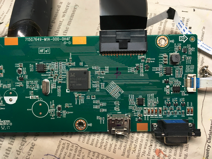
This is the video side, far right (white) connector goes to ON/OFF switch and bottom pin is #1. The large black connector at the top is to the LCN screen and right most pin is #1
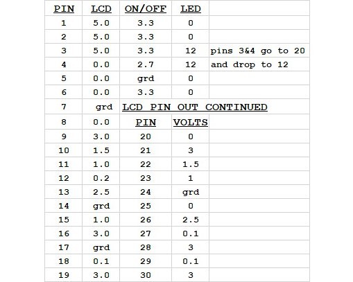
After tear down reattached connectors and turned on: Power light came on, LCD flickered several times, first 16 LEDs came on for 3 to 5 seconds and then both shut down, power light remained on. After that nothing came on except power light (LED) The following DC voltages were taken with everything connected to PCB and powered with 12V adapter that came with monitor
Checked individual LED's with 3volt power source and all seemed to burn (really bright), so think they are okay. Don't know how to start trying to jumper contacts out to get LED's to come on. There are no descriptions/legends on any of the components and have been unable to locate any diagrams for monitor or PCB. Know I can just junk it all and go buy string of LEDS and install, but would rather burn this one up trying to get it to work before buying something else.
Here's photo of LCD connection with voltages typed in best I could. The green bars are ground and appears that contacts 8 thru 30 connect to U1 thru U5, leaving contacts 1 thru 6 as possible control circuits (7 is ground).

Could the LEDs need an OK from the LCD before working? If so what's your best guess on how to supply that signal? Would LEDs need a VGA feed before working? Read on blog that by connecting all grounds on VGA female connector (pins 5 through 10) it might allow LED to come on, will this work?
So where do I start? Thanks for looking, Doug
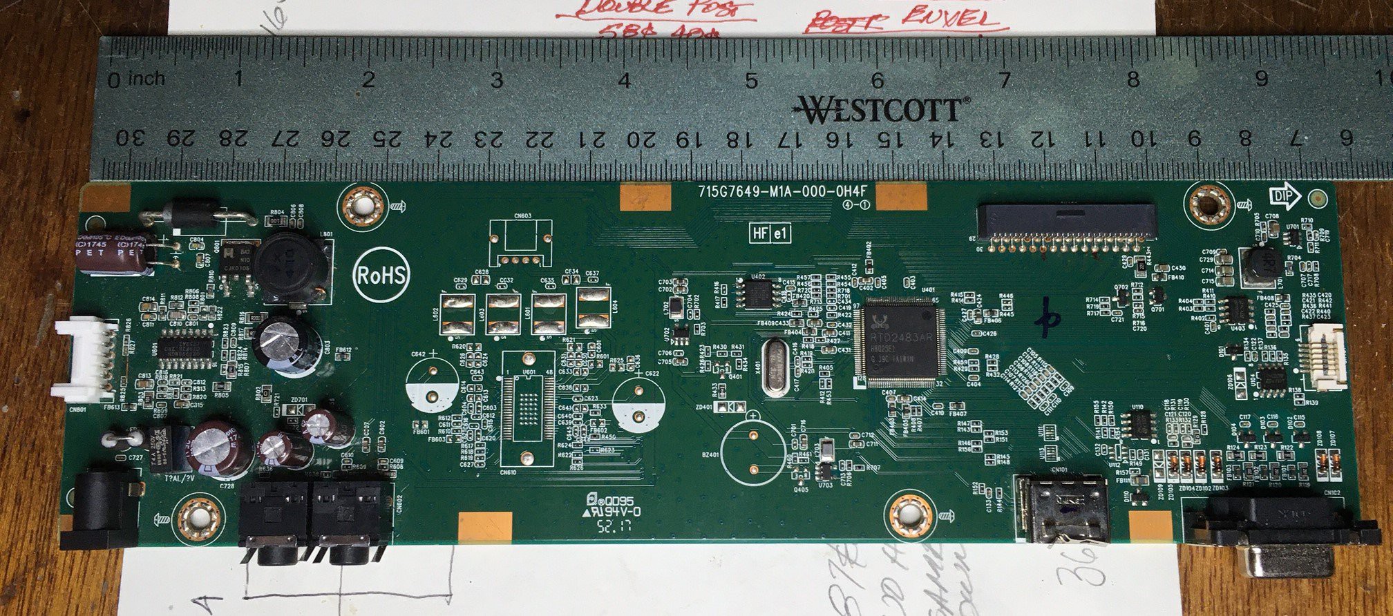
Monitor PCB only one board, left is "power" right is "video" section am assuming middle section would be for "audio" on other models
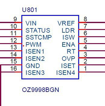
 Only schematic I could find was for OZ9998BGN not MGN

 Films4You

 icstation

 Stanislas Bertrand
what's the backlight IC markings? can't see from your pictures.
are PWM and ENA at 3.3V specifically at the moment when the backlight is off? what state are they when the backlight is on, as opposed to when it's off?