Using the color Unit of the M5Stack for the sensor is very easy.
Use the included Grove cable to make the connection.
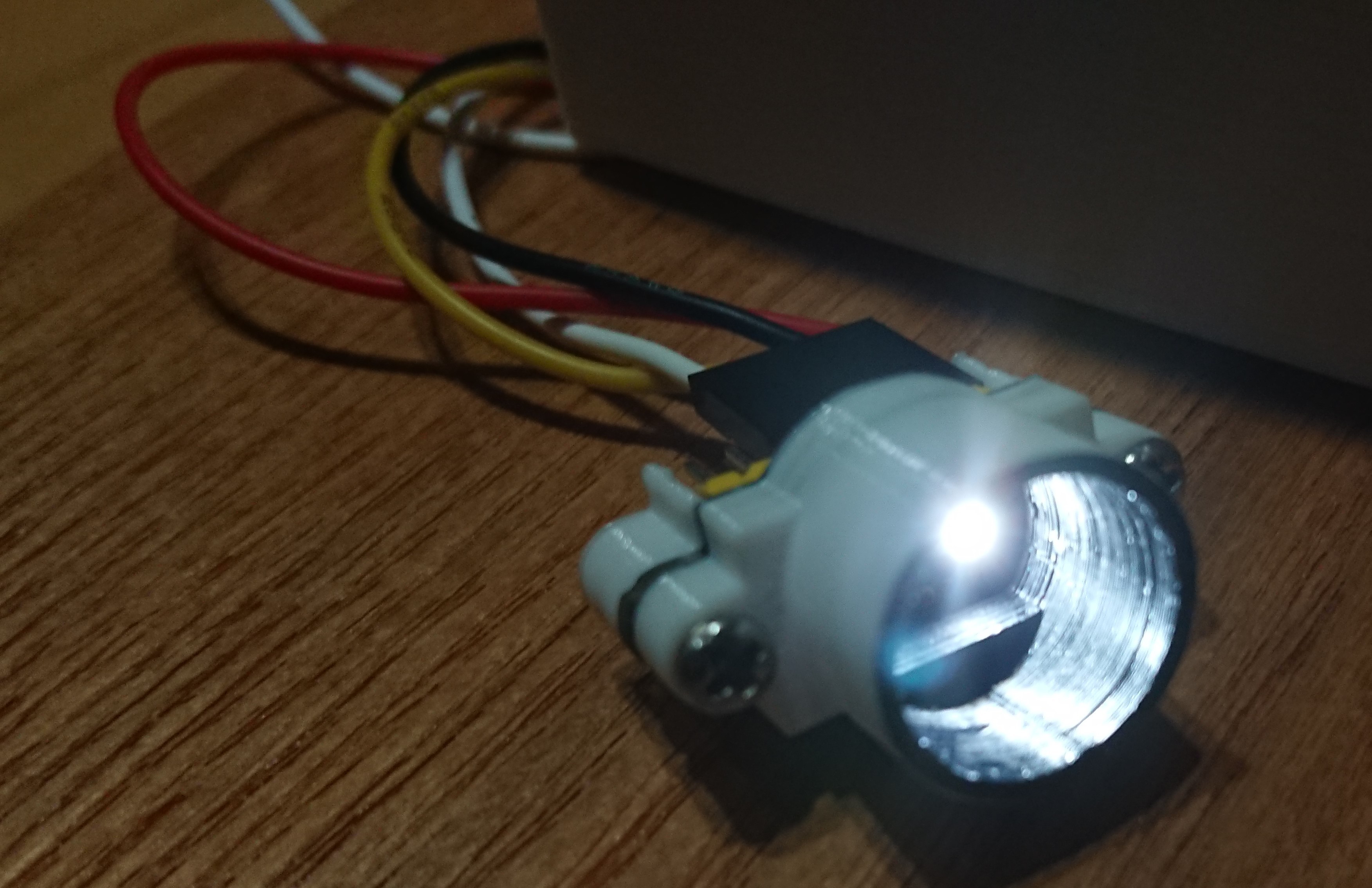
If you are using the TCS34725 development board, please solder the pin headers to the terminals. Next, screw on the two parts of the case output from the 3D printer. To stabilize the light environment, the 3D printer parts should be painted matte black.

Create a cable with Grove terminals on one side and a 2.54 pitch pin socket on the other side to connect the M5Stack to the TCS34725.
The connection should look like this.
| M5Stack(Glove connecotor) | TCS34725(QI connector) |
| Vout | 3V3 |
| G | GND |
| SCL | SCL |
| SDA | SDA |
 AIRPOCKET
Discussions
Become a Hackaday.io Member
Create an account to leave a comment. Already have an account? Log In.