 Lewis (DIY Machines)
-
1See what your going to make and the things you'll need:
For those of you who prefer to watch something instead of reading I have created a detailed tutorial video. Don't worry though, everything in the video (and a little more) is all explained in this guide. Though, even if you will read through this guide I highly recommend looking at the introduction in the video to get an idea of the effect the lights achieve. :)
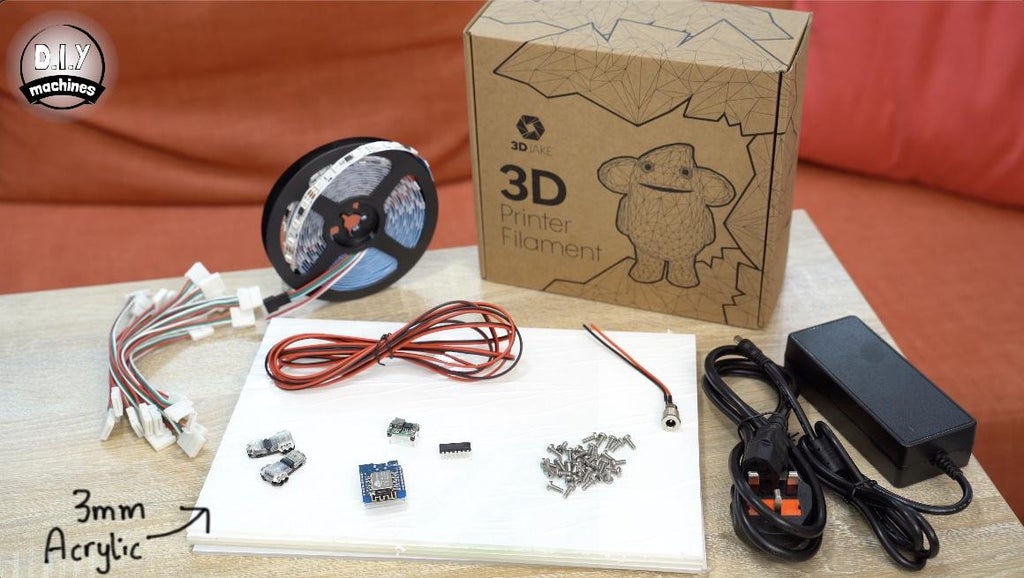
To build your own version of Geoleaf you're going to need just a few items and tools. None of these should be too tricky to find and I have included links to where you can find the items online:
- 12v WS2811 LED’s (A 5 meter roll is enough for 12 panels): https://geni.us/WS2811-60
- 10mm LED connectors - one per panel: https://geni.us/3Pin10mmLEDCable
- 3D Printer Filament: https://www.3djake.uk
- Acrylic sheets (1 A4 sheet = 3 triangles): https://geni.us/OpalFrostedA4Acrylic
- DC to DC Buck converter (Mini 360): https://geni.us/Mini360
- Logic Level Shifter (74AHCT125): https://geni.us/74AHCT125-LLS
- ESP8266 Dev Board: https://geni.us/wemosD1
- Plenty of M3x8 bolts: https://geni.us/NutsAndBolts
- Barrel connector suitable for at least 5amps https://geni.us/HighAmpDCBarrel
- 12v Power Supply (6 amp+): https://geni.us/12VPowerSupply6A
- Dual T splice connectors (x2): https://geni.us/DualTSplice
- Some 20AWG wire (0.8128mm in diameter): https://geni.us/20AWG
- 3M Command Hanging Strips: https://geni.us/CommandStrips
![]()
There are two different options for connecting the electronics together for this project. I learnt how to design a PCB for this project and have uploaded the design to PCBway where you can order a PCB of your own for just a few dollars/pounds. This is the simplest way to assemble the electronics:
- Projects PCB: https://geni.us/GeoLeafPCB
Or optionally you can use a piece of Adafruit PermaProto board to connect everything along with some wiring connectors for the higher current connections. You will find details of both methods later in the instructions
- PermaProto Board: https://geni.us/HalfPermaProto
- Wago Connectors: https://geni.us/Wago221
![]()
-
2Printing the Triangles - Walls
![]() The first thing we need to print are the sides of our triangles. The file for this is attached 'Triangle-Walls.stl'.
The first thing we need to print are the sides of our triangles. The file for this is attached 'Triangle-Walls.stl'.I printed mine in 3D Jakes ecoPLA Matt Black as I wanted it to contrast with the grey walls in my home office but you can use a different color if you prefer. As I will be using fourteen illuminated triangles in my end design I will print fourteen of these 'walls'.
My print settings were:
- 0.3mm layer height
- No supports
- No brim
- 30% infill
This resulted in a print time of roughly 1 hour 27 minutes per panel.
If you would like to add in some square illuminated panels than you can find the optional files for the squares here on Etsy: https://www.etsy.com/uk/listing/1067981962 . The donations received through people buying the files for the optional square panels helps to fund the next project I am working on - but please note this is optional and not necessary to complete the
-
3Cutting the Acrylic
For this step you will need:
- Acrylic sheets
- Saw
- Pencil
I am using some 3mm thick opal acrylic to diffuse the light for this project. I purchased some A4 sheets which we can cut three panels worth of acrylic diffusers from. My fourteen triangles therefore required five A4 sheets.
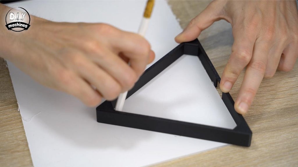
You can use a pencil to mark on the sheets (don't remove the protective film from them yet) an outline of the shape we need to cut. To do this, take one of your 3D printed triangular walls and place it onto the acrylic sheet so that the holes for the bolts is facing downwards. You can then trace the inside of this shape.
![]()
![]()
![]()
There are several ways that you can cut a sheet of acrylic, such as scorring and then snapping, hot wires or saw blades. This is beyond the scope of this Instructable for me to go through the pros and cons of each method.
![]()
![]()
I decided to cut mine with a fret saw. A hand saw or similar would work just as well. Once you have cut the shapes you can test there fit inside one of the triangles which will then allow you to trim any excess off before you remove the protective films from both sides of each of the panels.
![]()
-
4Gluing the Acrylic
![]()
For this step you will need:
- Super Glue
Once they have all been cut, checked to fit properly, and had their protective films removed you can then set about gluing them into place inside of the triangles.
![]()
![]()
To do this, push fit the acrylic and then check you are happy with the fit when viewed from the front. If so, turn it back around and use some generous dabs of super glue in the corners. Repeat this for all of your triangles before allowing them some time to cure before continuing to work with them.![]()
-
5Preparing the LEDs
![]()
For this step you will need:
- WS2811 12v LEDs (supplied on a roll)
- 3 Pin 10cm Wire Connectors
![]() Unlike the more commonly used Neopixels/WS2812B LEDs the WS2811 LEDs which we are using have one controller (black integrated circuit package) for every three LEDs. Because of this please pay close attention to where you can cut the strips every three LEDs.
Unlike the more commonly used Neopixels/WS2812B LEDs the WS2811 LEDs which we are using have one controller (black integrated circuit package) for every three LEDs. Because of this please pay close attention to where you can cut the strips every three LEDs.![]()
![]()
Each of our triangles will require about 40cm worth of LEDs which works out as having 8 segments of three LEDs on each strip.
![]() Once you have cut as many of these as you have triangles (14 in my case) you can then attach an LED connector wire to each of the incoming sides of the LED strips. You can work out the incoming side as the arrows showing the direction of data transfer through the strips is pointing away from it.
Once you have cut as many of these as you have triangles (14 in my case) you can then attach an LED connector wire to each of the incoming sides of the LED strips. You can work out the incoming side as the arrows showing the direction of data transfer through the strips is pointing away from it.![]() When adding the LED connector don't forget to also ensure that the red wire on the connector is connecting to the 12v pad on the LED strip. If we confuse our power wires during this project we are likely to damage something later when we apply power to the project.
When adding the LED connector don't forget to also ensure that the red wire on the connector is connecting to the 12v pad on the LED strip. If we confuse our power wires during this project we are likely to damage something later when we apply power to the project. -
6Fitting to Inside Triangular Panels
![]() Before we fit this into the inside of our triangular panels you should remove all but the last 1cm of self adhesive backing from the rear of the strips. Having the last 1cm of backing on the unconnected end will make it much easier to slide the LED connector onto this end later on in the build.
Before we fit this into the inside of our triangular panels you should remove all but the last 1cm of self adhesive backing from the rear of the strips. Having the last 1cm of backing on the unconnected end will make it much easier to slide the LED connector onto this end later on in the build.![]() Add some glue to the connector and then position on the inside of the cutout in the triangle's walls. It should be positioned so that the red wire on the connector is on the top side which will result in the LEDs heading away to the left in a clock wise direction. Start pressing the LEDs firmly into place around the interior whilst keeping them as close to the top edge as possible. This will help to improve the diffusion of the LEDs later.
Add some glue to the connector and then position on the inside of the cutout in the triangle's walls. It should be positioned so that the red wire on the connector is on the top side which will result in the LEDs heading away to the left in a clock wise direction. Start pressing the LEDs firmly into place around the interior whilst keeping them as close to the top edge as possible. This will help to improve the diffusion of the LEDs later.![]() Complete this process to combine each LED strip with a triangle panel.
Complete this process to combine each LED strip with a triangle panel.![]()
-
7Laying Out the Design
![]()
This is one of the fun but tricky stages - deciding how you want to lay out your Geoleaf panels.
Start with your first triangle where you will intend to connect the power and control electronics later. (The control electronics is housed in the small grey rectangle I showed you earlier in the intro of the video). From this starting point, keep positioning each additional triangles connector up against a side of the previous triangle a create your layout.
Don't forget that we are currently looking at the project from the rear so once it has been hung on the wall it's shape will have flipped left to right. :)
-
8Preparing the Bases
![]()
For this step you will need:
- M3x8 bolts
We then need to print the bases for the triangles, one for each triangle.
I highly recommend printing this in white filament as it has a big impact on the diffusion effect (take a look at the below photo which shows the difference between using a black and white back panel).
![]()
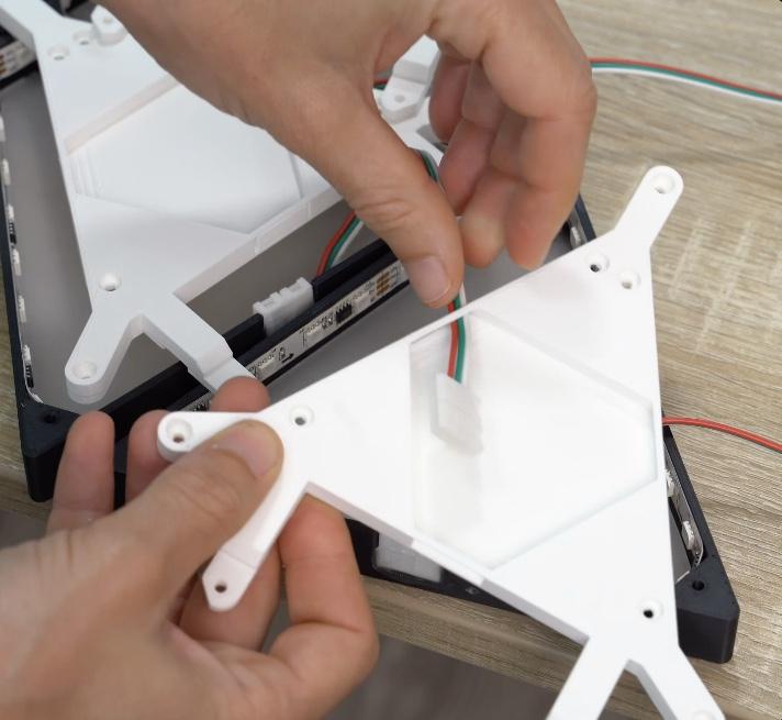
These are then temporarily laid out along the project so that the two legs on each print are pointing towards the same side as each of the triangles respective wire connectors. Go along the line of back panels and remove the pop-out walls on the print for the two sides of the triangle which adjoin another triangle.
![]()
![]()
![]()
Starting from the first triangle, take the LED connector from the next triangle and pass it though the triangles holes we just popped the panels out of. Connect the connector to the unconnected end of the LEDs in this triangle and then use a dab of glue to hold the connector in place over the top of the existing one (check the photo's - it is a little difficult to describe in words).
![]()
![]() Keep the connector up away from the acrylic to minimise any shadows it might cause showing on the other side of the acrylic.
Keep the connector up away from the acrylic to minimise any shadows it might cause showing on the other side of the acrylic.![]() Use three M3x8 bolts to attach this panel to the triangle in the three corners. Repeat this for the first five triangles but additionally use two more bolts to attach the legs of the triangle to the previous one. This is how the shape is formed.
Use three M3x8 bolts to attach this panel to the triangle in the three corners. Repeat this for the first five triangles but additionally use two more bolts to attach the legs of the triangle to the previous one. This is how the shape is formed.![]()
![]()
![]()
![]()
We need to do something a little different to every 6th panel, I'll explain more in the next step.
-
9Voltage Boosting
For this step you will need:
- 10cm lengths of 20AWG wire
- Soldering iron
![]() After every five panels we need to add a couple of 10cm long wires to a 12v and GND point on the next LED strip so that we can inject a boost of 12v power later. This is because the wiring in the LED strip is thin and we suffer what’s called ‘Voltage Drop’ the further we go along the wire. This will show itself as dimming LEDs that also appear to be tinted brown.
After every five panels we need to add a couple of 10cm long wires to a 12v and GND point on the next LED strip so that we can inject a boost of 12v power later. This is because the wiring in the LED strip is thin and we suffer what’s called ‘Voltage Drop’ the further we go along the wire. This will show itself as dimming LEDs that also appear to be tinted brown.![]() Solder two 10cm long wires to the first 12v and ground pads just along from the connector o this 6th panel.
Solder two 10cm long wires to the first 12v and ground pads just along from the connector o this 6th panel.![]()
![]()
We will connect these two wires to the rest of the project later - for now they can be disregarded and we can carry on fitting the back panel for this light and the next five before attaching another couple of wires to the 12th panel.
Keep repeating this pattern until every panel has a back plate.
-
10Prepare the Mini360 DC-DC Converter
For this step you will need:
- Mini360 DC-DC buck converter
- Small screwdriver
- Multimeter
- 12v power supply
![]()
Before we can connect the Mini360 to the rest of our circuit later we need to configure it's output voltage. The Mini360 can be set to output between 1v to 17v - we need it to output a teeny tiny smidge over 5v.
![]()
To do this we can temporarily hook up its two inputs (check the underside of the board) to our 12v power supply which we will be using for the project, and to its two outputs we need to connect a multimeter.
![]()
Set the multimeter to measure a voltage up to 20v and switch on the power supply. You can then use a small screwdriver to turn the potentiometer whilst watching the output. Aim for something between 5v and 5.05v.
Once you have done this it can be disconnected and put to one side for use later.
GeoLeaf
Customisable 3D printable geometric light panels which connect to Hue and Alexa to brighten and personalise your space.

 The first thing we need to print are the sides of our triangles. The file for this is attached 'Triangle-Walls.stl'.


 Unlike the more commonly used Neopixels/WS2812B LEDs the WS2811 LEDs which we are using have one controller (black integrated circuit package) for every three LEDs. Because of this please pay close attention to where you can cut the strips every three LEDs.

 Once you have cut as many of these as you have triangles (14 in my case) you can then attach an LED connector wire to each of the incoming sides of the LED strips. You can work out the incoming side as the arrows showing the direction of data transfer through the strips is pointing away from it.
 When adding the LED connector don't forget to also ensure that the red wire on the connector is connecting to the 12v pad on the LED strip. If we confuse our power wires during this project we are likely to damage something later when we apply power to the project.
 Before we fit this into the inside of our triangular panels you should remove all but the last 1cm of self adhesive backing from the rear of the strips. Having the last 1cm of backing on the unconnected end will make it much easier to slide the LED connector onto this end later on in the build.
 Add some glue to the connector and then position on the inside of the cutout in the triangle's walls. It should be positioned so that the red wire on the connector is on the top side which will result in the LEDs heading away to the left in a clock wise direction. Start pressing the LEDs firmly into place around the interior whilst keeping them as close to the top edge as possible. This will help to improve the diffusion of the LEDs later.
 Complete this process to combine each LED strip with a triangle panel.


 Keep the connector up away from the acrylic to minimise any shadows it might cause showing on the other side of the acrylic.
 Use three M3x8 bolts to attach this panel to the triangle in the three corners. Repeat this for the first five triangles but additionally use two more bolts to attach the legs of the triangle to the previous one. This is how the shape is formed.


 After every five panels we need to add a couple of 10cm long wires to a 12v and GND point on the next LED strip so that we can inject a boost of 12v power later. This is because the wiring in the LED strip is thin and we suffer what’s called ‘Voltage Drop’ the further we go along the wire. This will show itself as dimming LEDs that also appear to be tinted brown.
 Solder two 10cm long wires to the first 12v and ground pads just along from the connector o this 6th panel.


Discussions
Become a Hackaday.io Member
Create an account to leave a comment. Already have an account? Log In.