 Lewis (DIY Machines)
-
11Prepare the ESP3266 (Wemos D1 Mini)
![]()
The ESP8266 is next, connect it to your computer using a USB cable and then navigate to https://install.wled.me/ using the chrome web browser.
![]()
Press ‘Install’ and then choose your board. Once completed we can then disconnect this and set it aside for now as well. Easy huh? :)
-
12Printing the Control Panel Housing
![]()
We need a couple more prints for the electronics. The control base and control cover.
I printed both of mine with colours and materials that match the rest of the project - white and matt black.
-
13The PCB / Perforated Board Options
![]() There are two methods for connecting the electronics together for this project, as mentioned at the beginning. This is either using the PCB which I designed for this project or using something like an Adafruit Perma-proto to connect the electronics and some wago connectors for the higher amperage circuits.
There are two methods for connecting the electronics together for this project, as mentioned at the beginning. This is either using the PCB which I designed for this project or using something like an Adafruit Perma-proto to connect the electronics and some wago connectors for the higher amperage circuits.![]() I really recommend the PCB method - not just because I'm proud of my very new but growing PCB skills, but because it comes with labels and outlines for all of the components and requires significantly less soldering.
I really recommend the PCB method - not just because I'm proud of my very new but growing PCB skills, but because it comes with labels and outlines for all of the components and requires significantly less soldering.To order a PCB you can go to PCBWays website where there is a page for this project: https://geni.us/GeoLeafPCB here you can order 5 copies of the PCB delivered for only about $8 / £7 if you choose the slower shipping times. All the settings and configuration for the PCB order have been pre-filled, you only need to add it to your basket and proceed with payment.
![]()
The rest of this Instructable will explain how to proceed with the PCB, however, if you would rather use a Perma-proto board and wire connectors then I have drawn out the wiring diagram which you can find above.
-
14Assembling the PCB - Components
![]() For this step you will need:
For this step you will need:- PCB
- ESP8266 (that we flashed with WLED earlier)
- Logic Level Converter (LLC)
- Mini360 (which we set to output 5v earlier)
Once you have your PCB we can add the three main components by inserting their legs though their respective holes for their location on the PCB.
You need to ensure that the components are inserted in the correct orientation:
- The ESP8266 should have its USB port facing upwards as indicated in its outline on the board.
- The Mini360 has positive and negative labels for both the input and output on the underside of it's board. This should be matched with its outline.
- The logic level shifter has a small semi circle indent at one end, which should be on the same side as the ESP8266 as indicated by the markings for its outline.
![]() After you have checked the components are oriented correctly the board can be turned over and soldered from the other side.
After you have checked the components are oriented correctly the board can be turned over and soldered from the other side.![]()
-
15Assembling the PCB - Power
For this step you will need:
- PCB Assembly
- 5A (or greater) DC Barrel
- Control Base (3D Printed)
![]()
The female barrel connector for our power supply is added into the 3D printed housing from the outside of the print and then secured with the included washer and nut.
![]() Its two leads are soldered to the respective positive and negative terminal on the far left of the PCB labelled as '12v Input'. If the leads on your connector are rather long then you might want to consider reducing their length before soldering them into place.
Its two leads are soldered to the respective positive and negative terminal on the far left of the PCB labelled as '12v Input'. If the leads on your connector are rather long then you might want to consider reducing their length before soldering them into place.![]()
![]() To see if they are too long you can temporarily hold the PCB over the four stand offs in the 3D print to see just how far it needs to reach.
To see if they are too long you can temporarily hold the PCB over the four stand offs in the 3D print to see just how far it needs to reach. -
16Assembling the PCB - LEDs
Before we connect the first illuminated triangles LED connector to the PCB it should be trimmed down to about 5cm in length, removing the connector. We can then separate and strip the wires before soldering them to the PCB.
![]()
![]() These wires are best inserted from the rear of the PCB and soldered on the front side. They are to be connected as follows:
These wires are best inserted from the rear of the PCB and soldered on the front side. They are to be connected as follows:![]()
- Red wire -> 'LED-12V'
- Green wire -> 'LED-DATA'
- White wire -> 'LED-GND'
![]()
-
17Assembling the PCB - Power Boosting
For this step you will need:
- Length of 20AWG wire
- Dual T-splice wire connectors
- M3x8 bolts (x6)
![]()
We will turn our attention back to the pairs of unconnected wires now which we added to every 6th panel along the length of project earlier to help us inject 12v of power.
Cut a length of your twin core wire about 10% longer than the farthest wires which needs connecting as measured along the path of the triangular panels. We will trim any excess later.
![]()
Solder one end to the power boost pads on the main PCB passing them through the board from the rear (just like the LED wires) and soldering it on the frontside.
Four M3x8mm bolts are used to secure our PCB on top of the integral 3D printed standoffs. The Control Base can then be carefully turned over and attached to the bottom two feet of the first triangular panel using two more bolts.
![]()
![]()
The new length of wire we attached to the PCB can then be threaded through the length of the project using the same path as the LED wire connectors. When you reach the point where we added two additional wires to the 6th panel you can use one of the T-splices to connect the two power wires to the LEDs.
![]()
![]() Take a good look at your connector to ensure that the correct wire is connecting to the correct lead on the LED. The wiring of your connector may be different to mine. The ones I'm using have a small diagram imprinted on the casing which shows how they are to be used.
Take a good look at your connector to ensure that the correct wire is connecting to the correct lead on the LED. The wiring of your connector may be different to mine. The ones I'm using have a small diagram imprinted on the casing which shows how they are to be used.![]() Do this by first clamping the connector to the long wire we're threading through. Then you can nestle the connector down between the two triangles. The wires we soldered to the LED strip earlier were purposely oversized so we first need to trim them to a more appropriate length. They can then be inserted into the end of the connector and clamped into place.
Do this by first clamping the connector to the long wire we're threading through. Then you can nestle the connector down between the two triangles. The wires we soldered to the LED strip earlier were purposely oversized so we first need to trim them to a more appropriate length. They can then be inserted into the end of the connector and clamped into place.![]() Resume passing the long wire through the projects length again until you reach the next pair of wire attached to the 12th illuminated panel. Repeat the same process to attach it to the LEDs power injection wires. If this is your last such boosting point, you can trim of the remainder of the wire.
Resume passing the long wire through the projects length again until you reach the next pair of wire attached to the 12th illuminated panel. Repeat the same process to attach it to the LEDs power injection wires. If this is your last such boosting point, you can trim of the remainder of the wire. -
18Adding the Lid
![]() The project can then be flipped over so we can see the much smarter front side. The lid for the control panel is then slid on over the top with friction holding it snuggly into place.
The project can then be flipped over so we can see the much smarter front side. The lid for the control panel is then slid on over the top with friction holding it snuggly into place. ![]()
That's all of the electronics wiring complete! Nice one. :)
-
19WLED - Getting Connected
![]() Connect your 12v power supply to the barrel connector at the bottom of the project and switch on the power. All going well, you should see the first three or four triangles spring into life.
Connect your 12v power supply to the barrel connector at the bottom of the project and switch on the power. All going well, you should see the first three or four triangles spring into life.![]() If you do not see this, disconnect the power and check your work done so far before progressing.
If you do not see this, disconnect the power and check your work done so far before progressing.![]() The easiest way to connect your smartphone or tablet is to scan the QR code in the photos above. This should connect you to the projects own wifi access point and present the first set-up screen.
The easiest way to connect your smartphone or tablet is to scan the QR code in the photos above. This should connect you to the projects own wifi access point and present the first set-up screen.![]()
If this does not work for you, or you would like to connect to the projects AP in a more traditional method then scan for the wi-fi network 'WLED-AP' and connect to it using the password 'wled1234'.
![]()
Once connected you can navigate to 4.3.2.1 in your devices web browser.
We can then proceed with the setup...
-
20WLED - Software Configuration
![]()
At this moment we have only a direct wi-fi connection to our project so we will configure it to connect to you main wi-fi network next. This is so that we can control it locally and using other services such as Alexa and Phillips Hue.
- Click ‘WIFI Settings’
- Enter name and password for your own wifi network in the top two boxes.
![]()
(Optionally you can also enter a mDNS address for accessing the configuration pages later instead of an having to use an IP address. I chose to call mine 'Geoleaf-Office'.)
![]()
- Once done, scroll to the bottom and press 'Save & Connect'.
The Wemos D1 Mini will now reboot which will only take a few seconds. Whilst this is happening you can now reconnect your phone to the same wifi network you connected the Geoleaf project to and navigate to the mDNS address you just chose, or the projects IP address.
We now need to tell our project some more information about the LEDs we have connected to it.
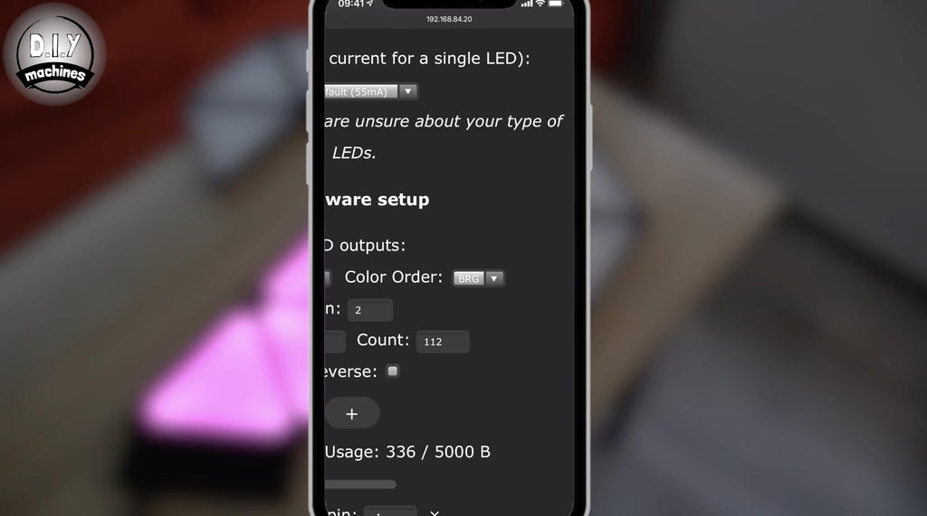
Once you have reconnected to the projects control page open the configuration page again but this time navigate to the 'LED Preferences'. On this page scroll down and update the 'LED count'. This should be the number of triangles you are using in the project x8. So for my 14 panels I will enter 112. (14x8).
![]()
You need to also set the maximum current to 3500 ma. This is important to keep the current within the capabilities of the project as I have shown you how to build it. It will only try to automatically and intelligently limit the maximum brightness of the LED's depending on how many are on at any moment and what colour they are showing (some colours require more energy than others to shine).
Finally under 'hardware setup' change the 'colour order' to BRG. (Blue Red Green).
![]()
We can verify the settings by heading back to the main page and cycling through the red, green and blue colours.
![]()
![]()
![]()
![]()
GeoLeaf
Customisable 3D printable geometric light panels which connect to Hue and Alexa to brighten and personalise your space.


 There are two methods for connecting the electronics together for this project, as mentioned at the beginning. This is either using the PCB which I designed for this project or using something like an Adafruit Perma-proto to connect the electronics and some wago connectors for the higher amperage circuits.
 I really recommend the PCB method - not just because I'm proud of my very new but growing PCB skills, but because it comes with labels and outlines for all of the components and requires significantly less soldering.
 For this step you will need:
 After you have checked the components are oriented correctly the board can be turned over and soldered from the other side.

 Its two leads are soldered to the respective positive and negative terminal on the far left of the PCB labelled as '12v Input'. If the leads on your connector are rather long then you might want to consider reducing their length before soldering them into place.
 To see if they are too long you can temporarily hold the PCB over the four stand offs in the 3D print to see just how far it needs to reach.
 These wires are best inserted from the rear of the PCB and soldered on the front side. They are to be connected as follows:


 Take a good look at your connector to ensure that the correct wire is connecting to the correct lead on the LED. The wiring of your connector may be different to mine. The ones I'm using have a small diagram imprinted on the casing which shows how they are to be used.
 Do this by first clamping the connector to the long wire we're threading through. Then you can nestle the connector down between the two triangles. The wires we soldered to the LED strip earlier were purposely oversized so we first need to trim them to a more appropriate length. They can then be inserted into the end of the connector and clamped into place.
 Resume passing the long wire through the projects length again until you reach the next pair of wire attached to the 12th illuminated panel. Repeat the same process to attach it to the LEDs power injection wires. If this is your last such boosting point, you can trim of the remainder of the wire.
 The project can then be flipped over so we can see the much smarter front side. The lid for the control panel is then slid on over the top with friction holding it snuggly into place.
 Connect your 12v power supply to the barrel connector at the bottom of the project and switch on the power. All going well, you should see the first three or four triangles spring into life.
 If you do not see this, disconnect the power and check your work done so far before progressing.
 The easiest way to connect your smartphone or tablet is to scan the QR code in the photos above. This should connect you to the projects own wifi access point and present the first set-up screen.


Discussions
Become a Hackaday.io Member
Create an account to leave a comment. Already have an account? Log In.