How it works
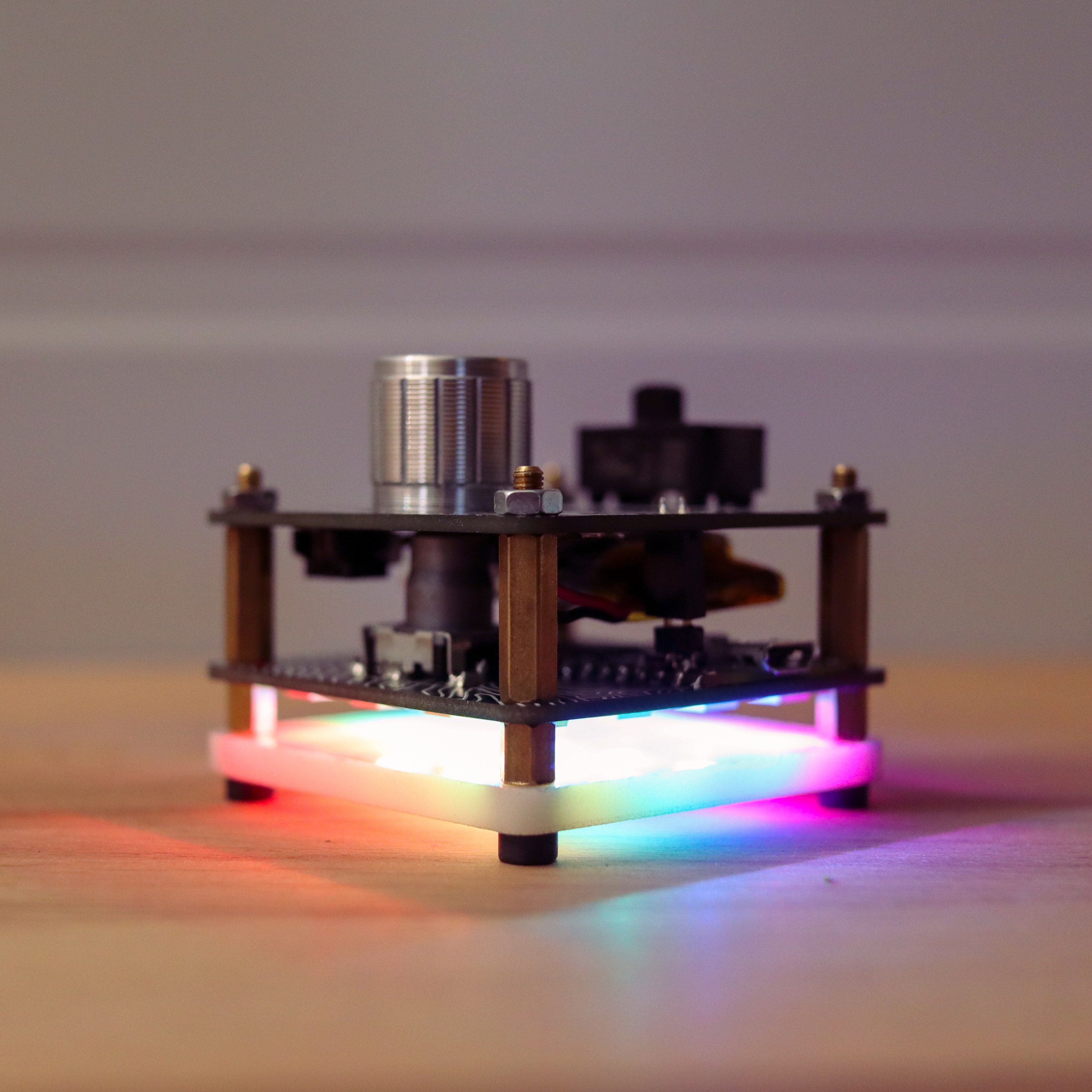
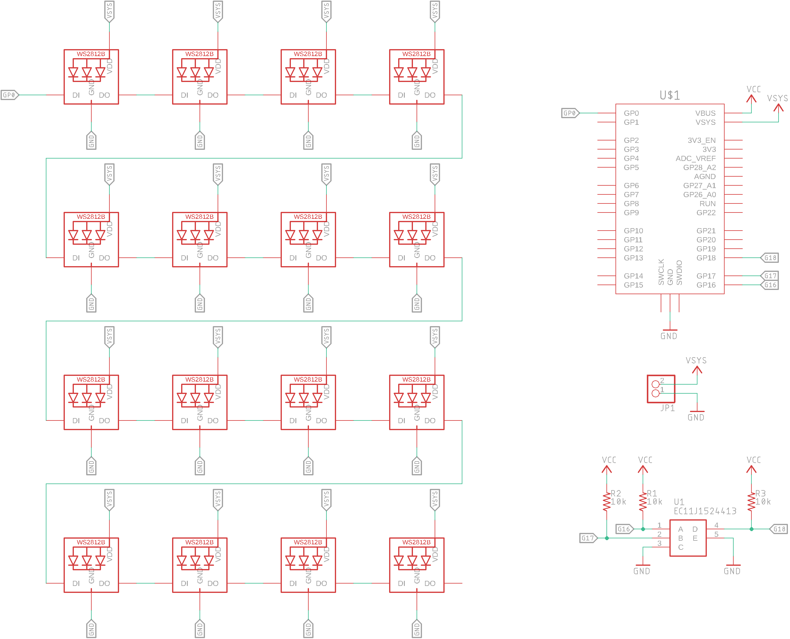
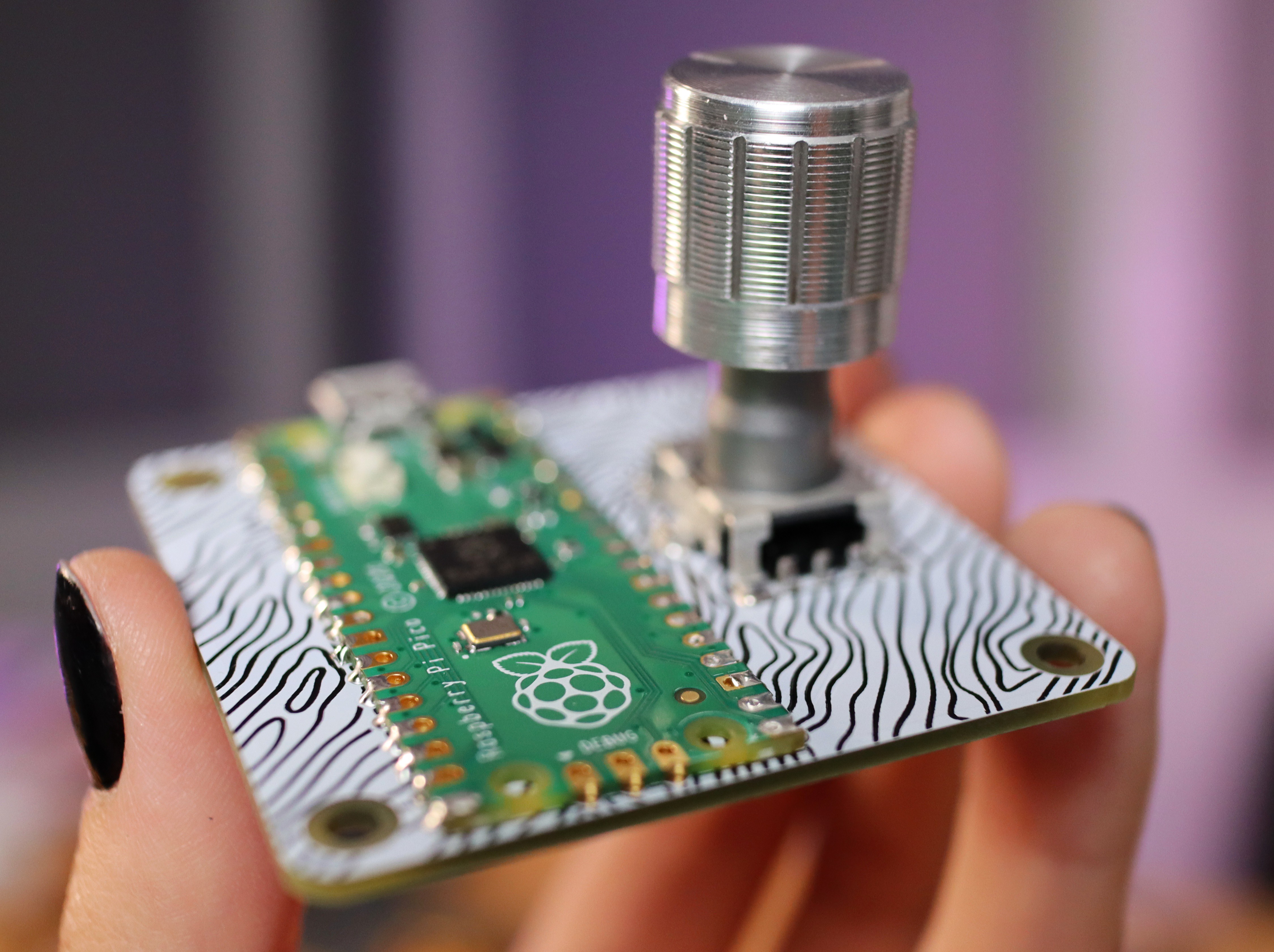
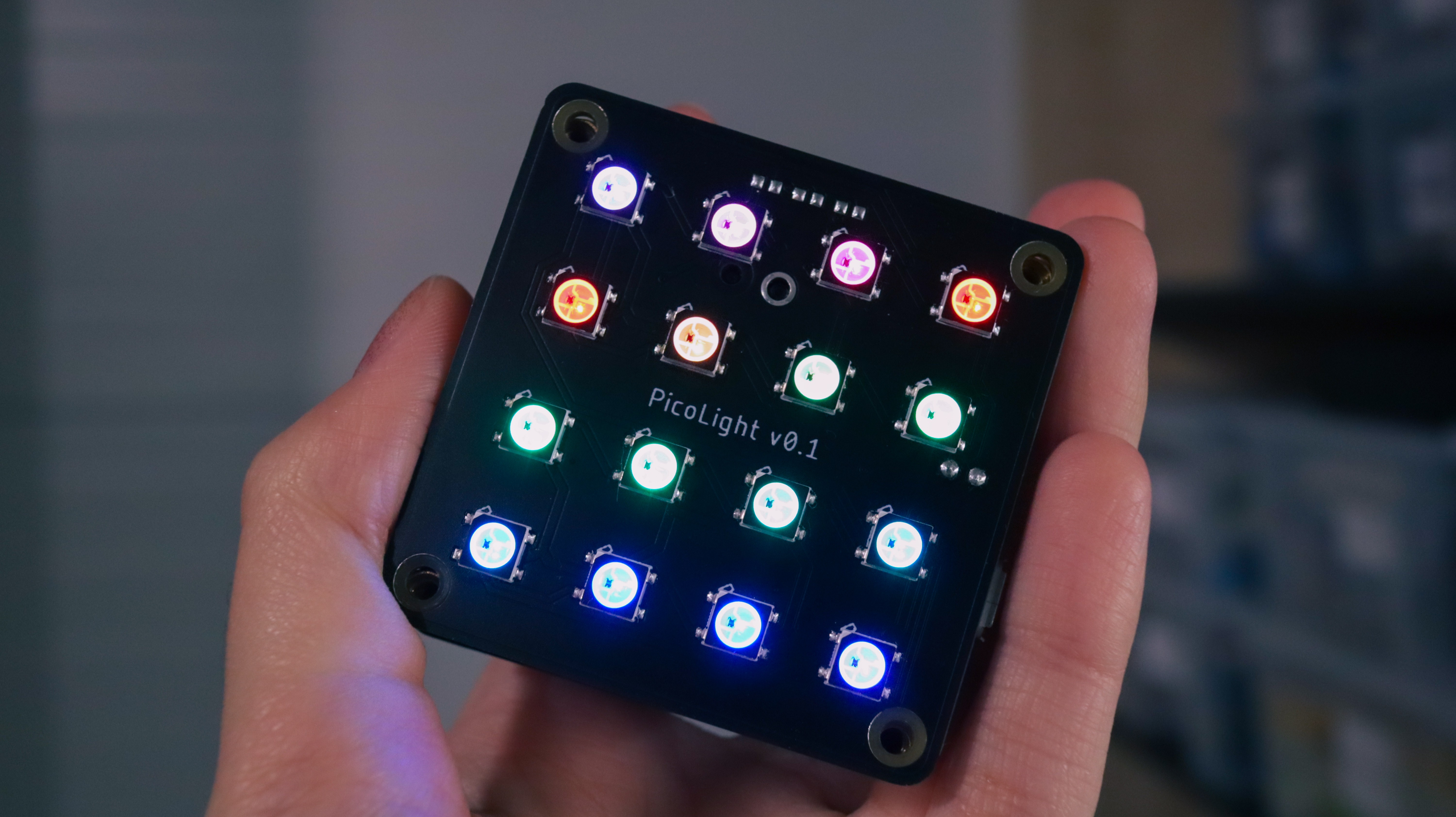
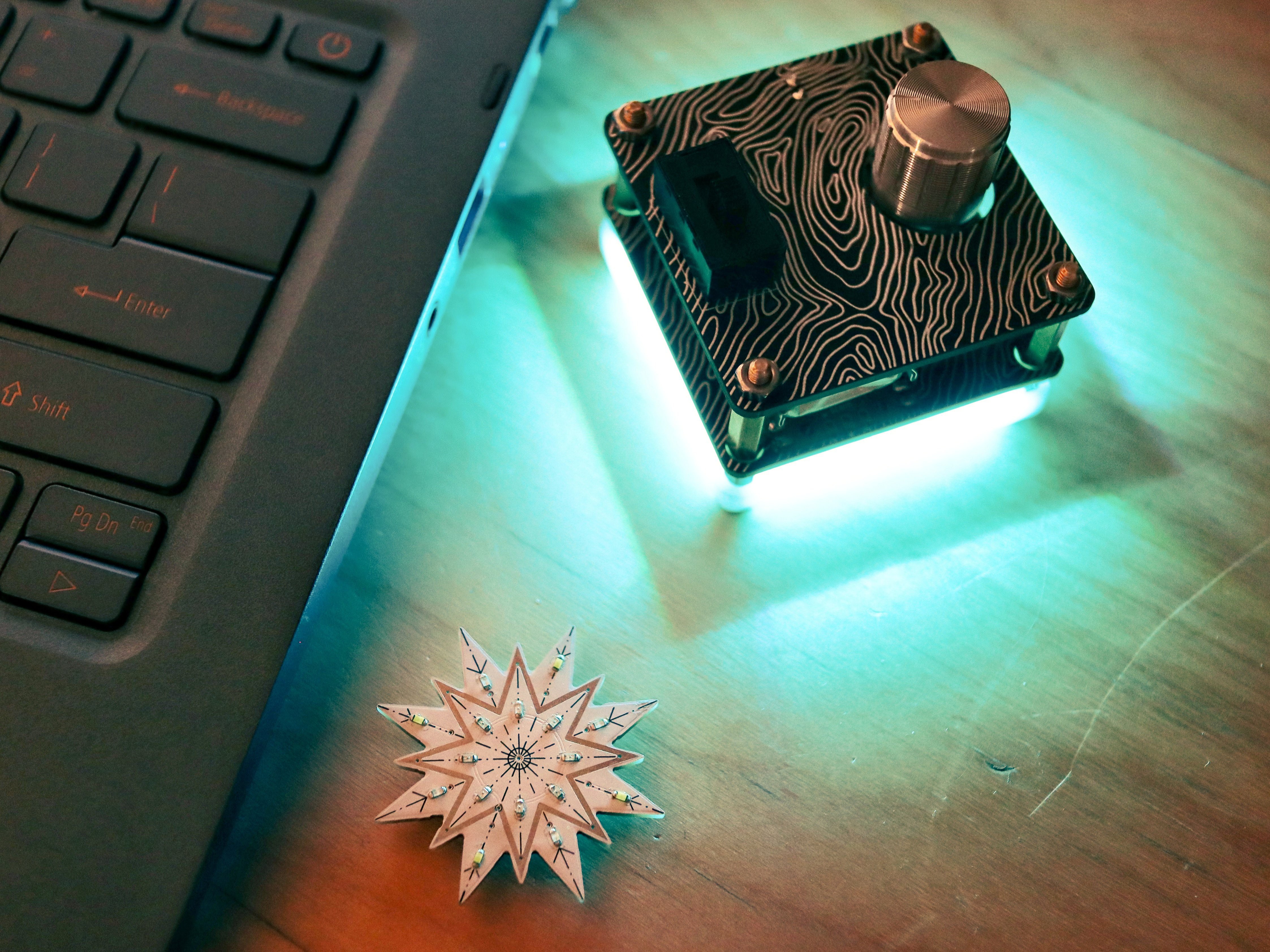
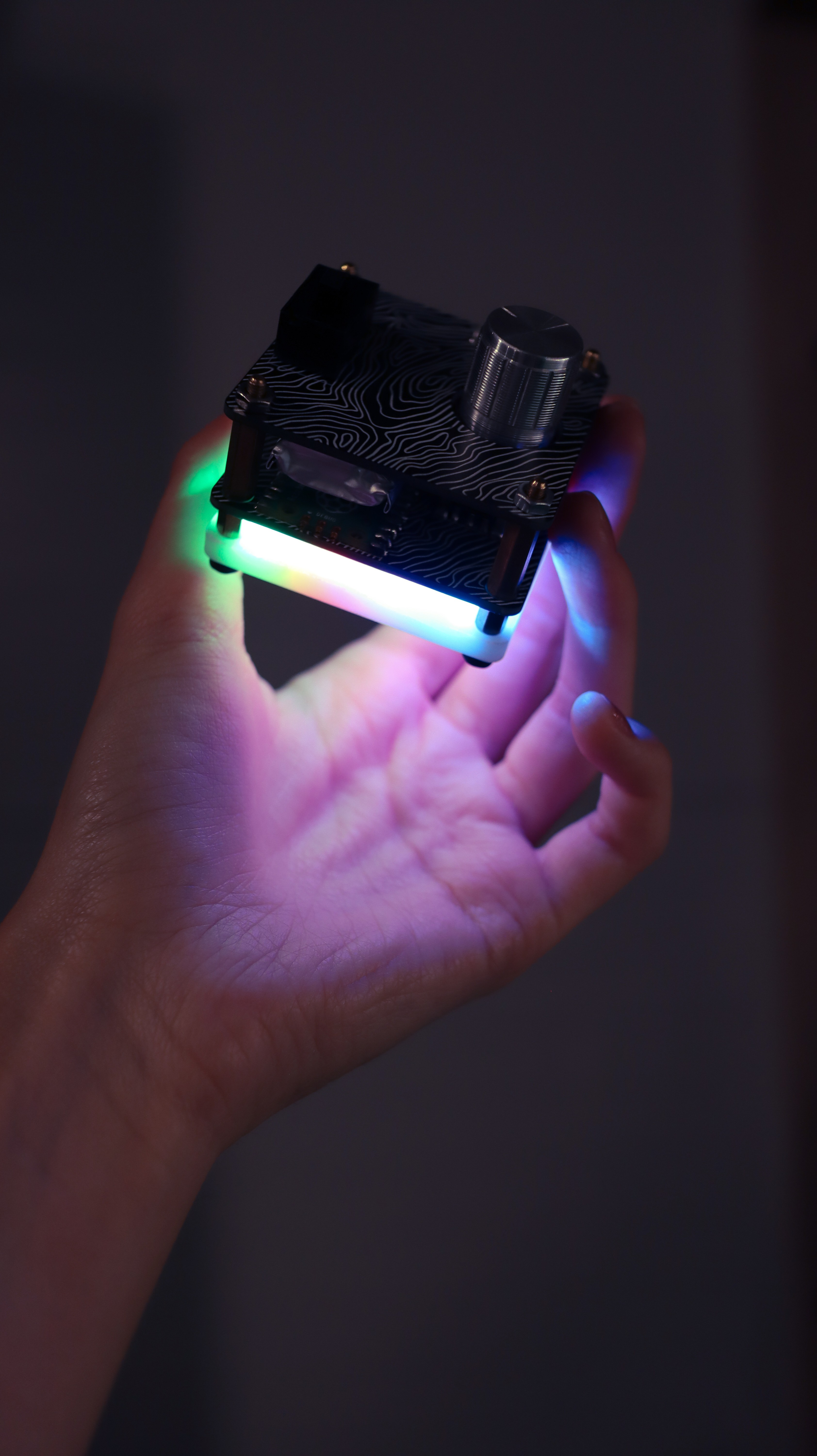
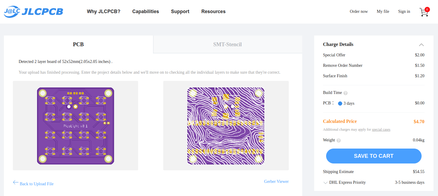
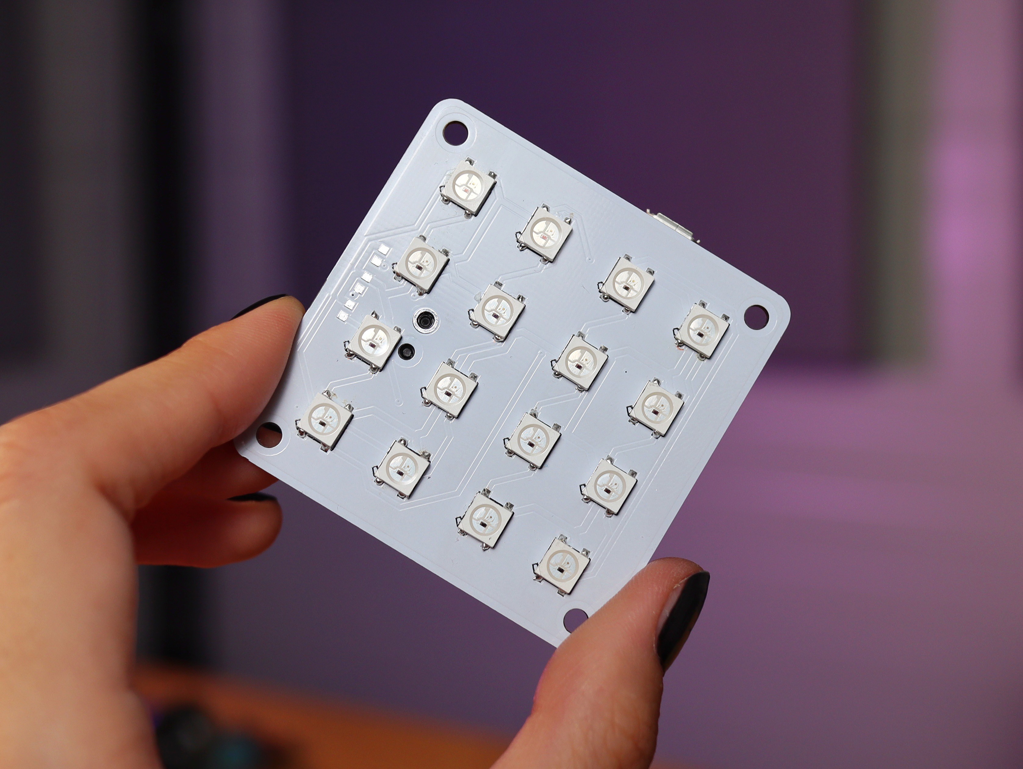
PicoLight consists of two PCBs and a white acrylic panel (which is great for diffusing the light) sandwiched together. One of the PCBs is a 4x4 Neopixel Matrix with a Raspberry Pi Pico on the back and a rotary encoder with push-button. The encoder is used for adjusting the colour and the intensity of the light.
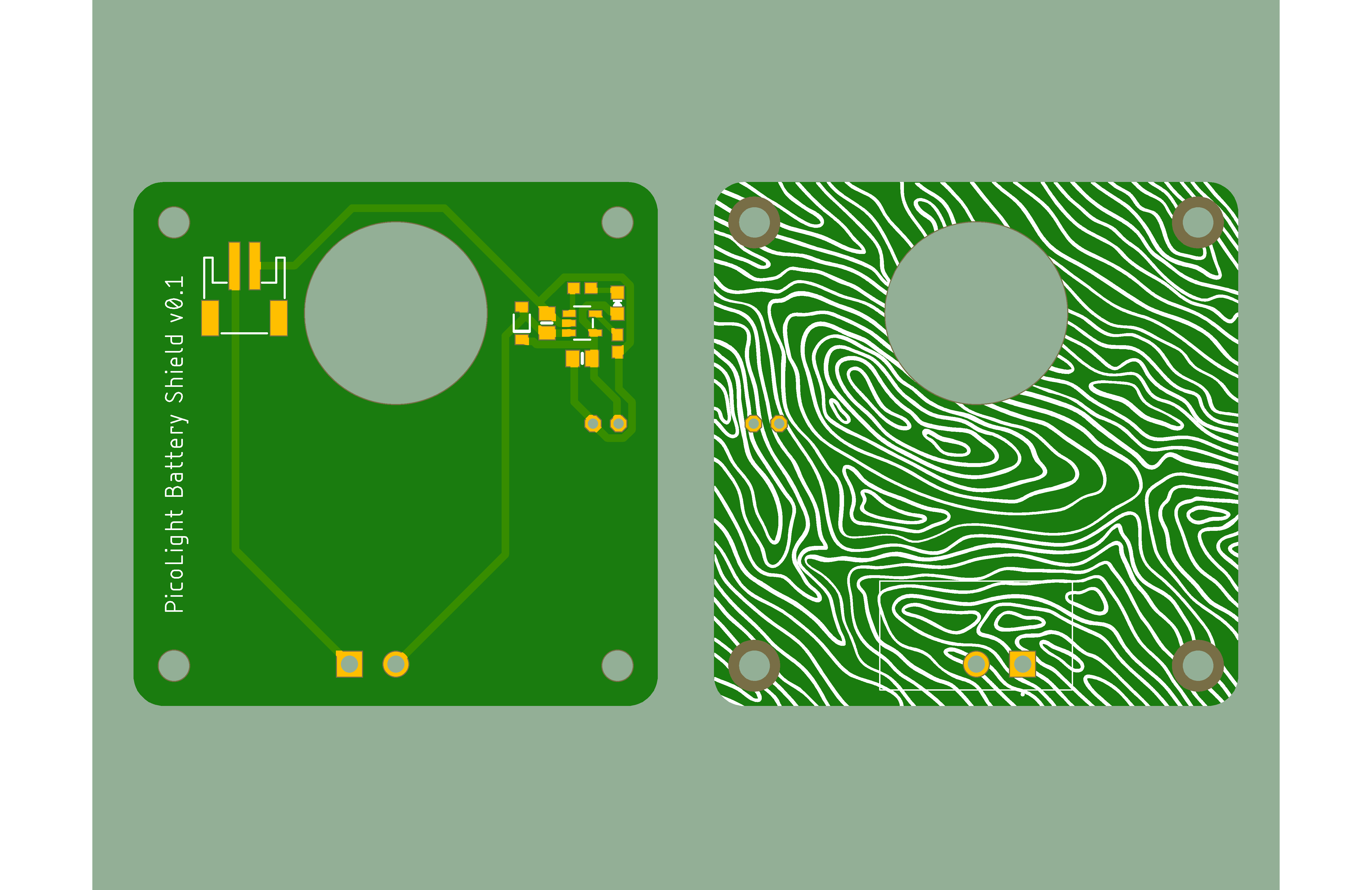
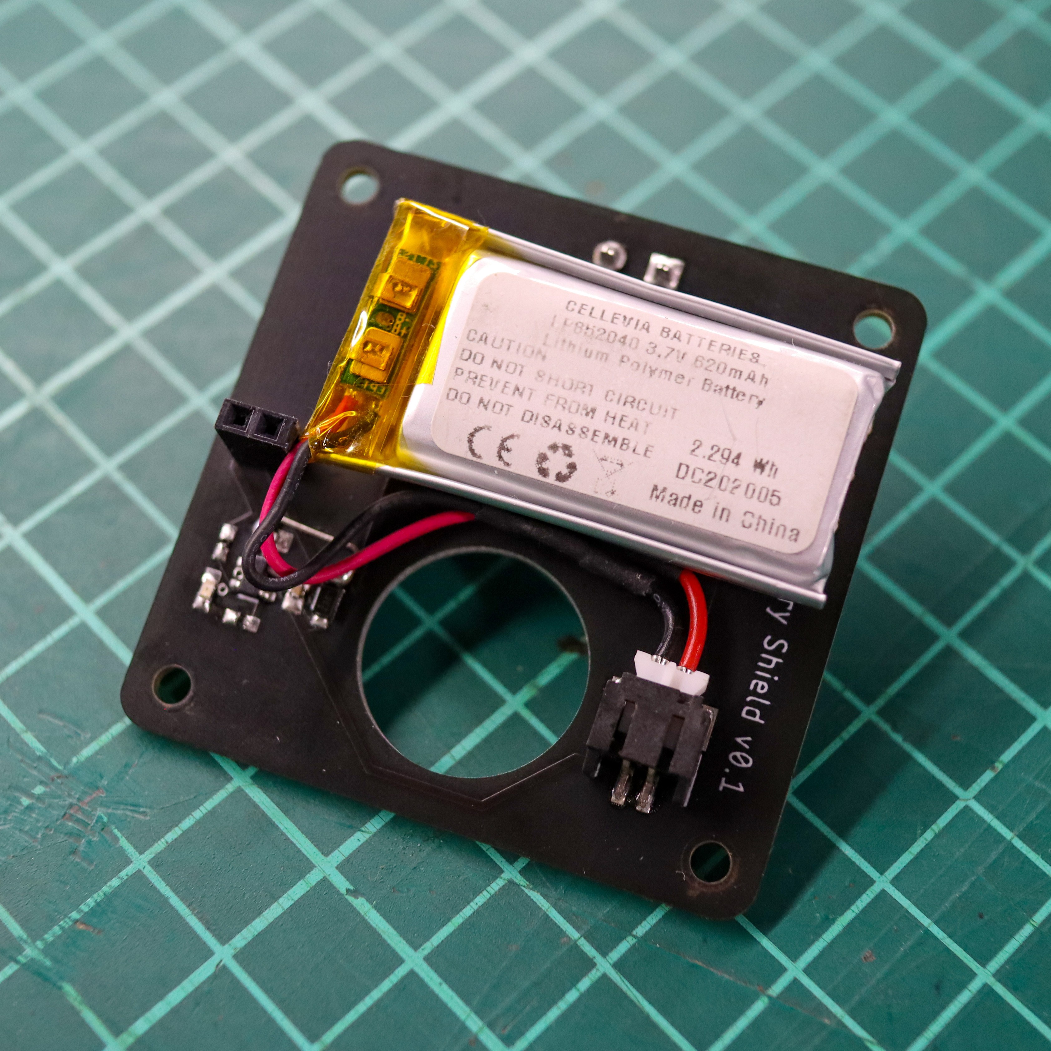
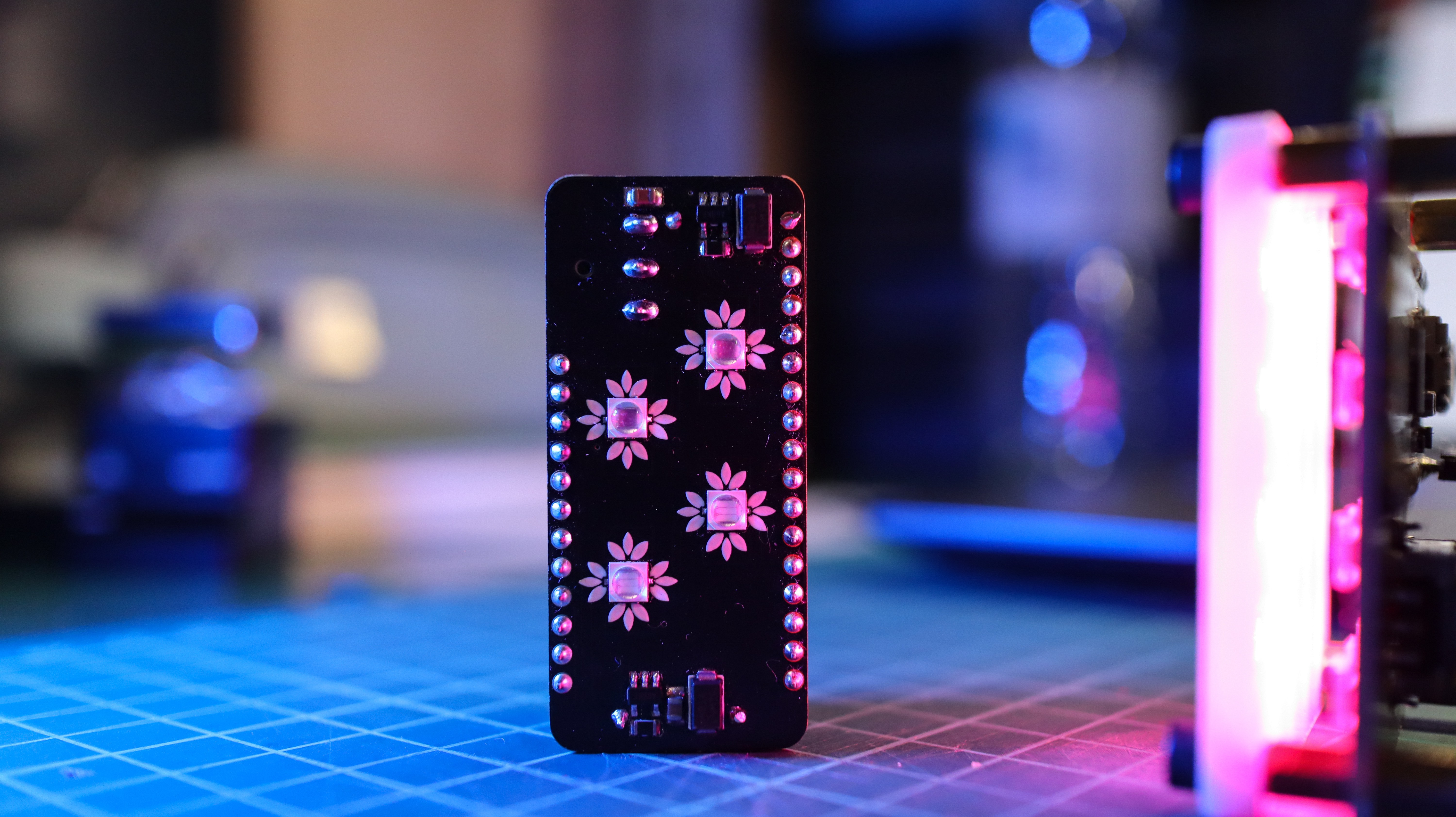
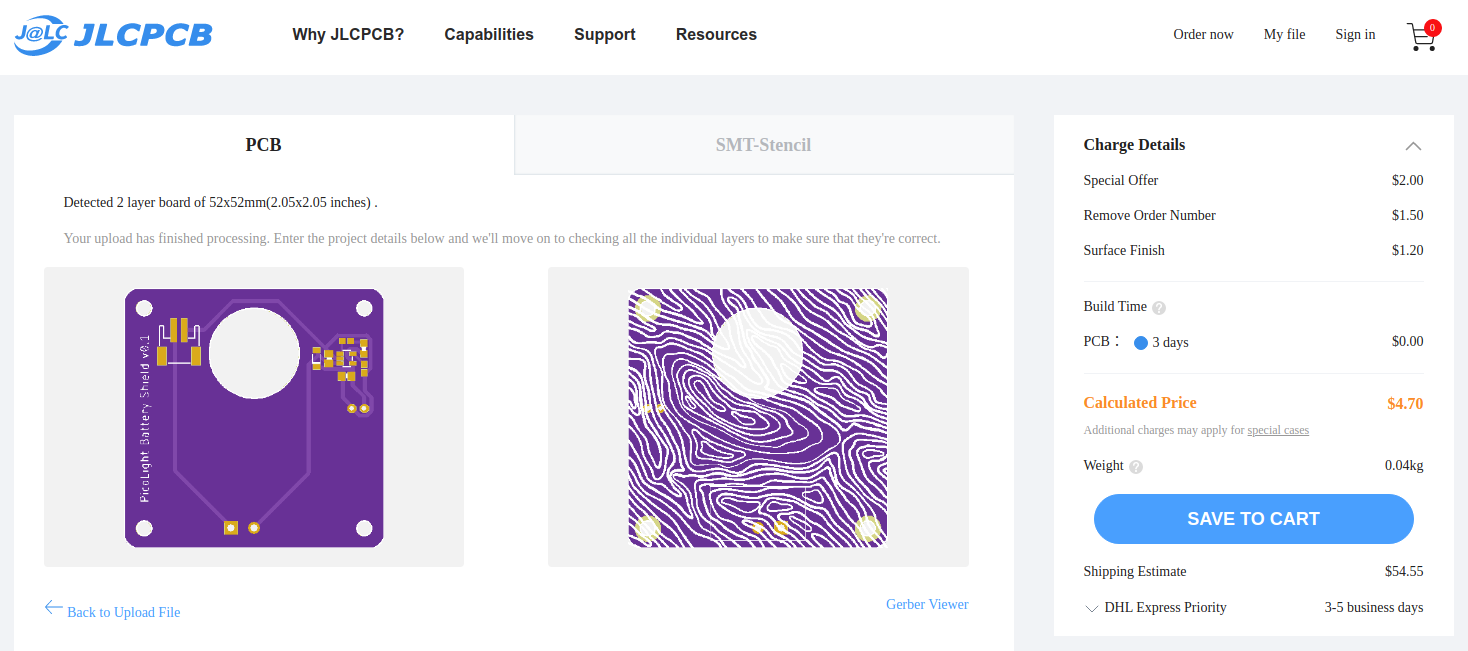
The other PCB is a LiPo battery shield which includes a charging circuit and a power switch. PicoLight can also be powered directly from the USB, without using this shield.
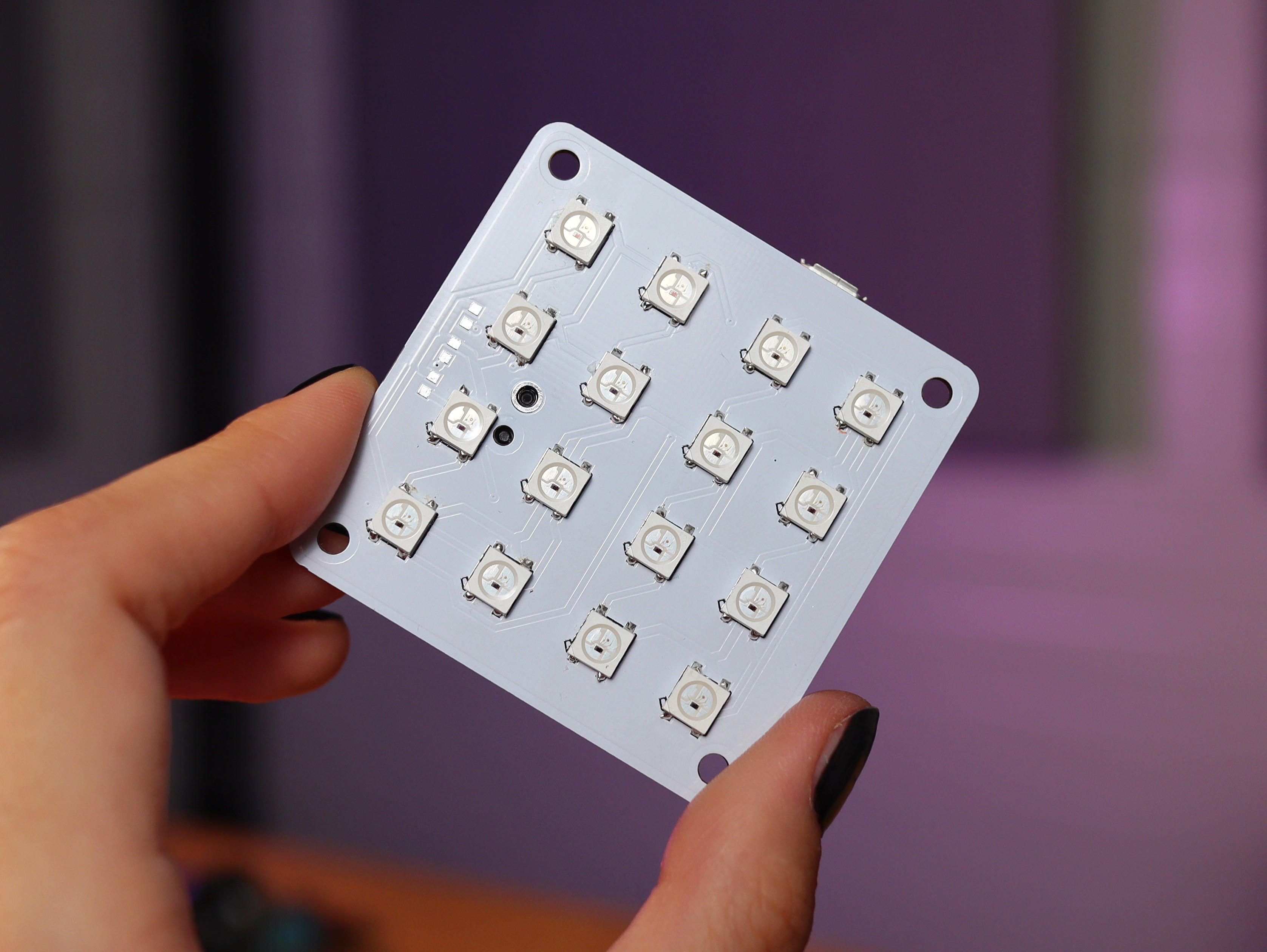
4x4 Neopixel Matrix
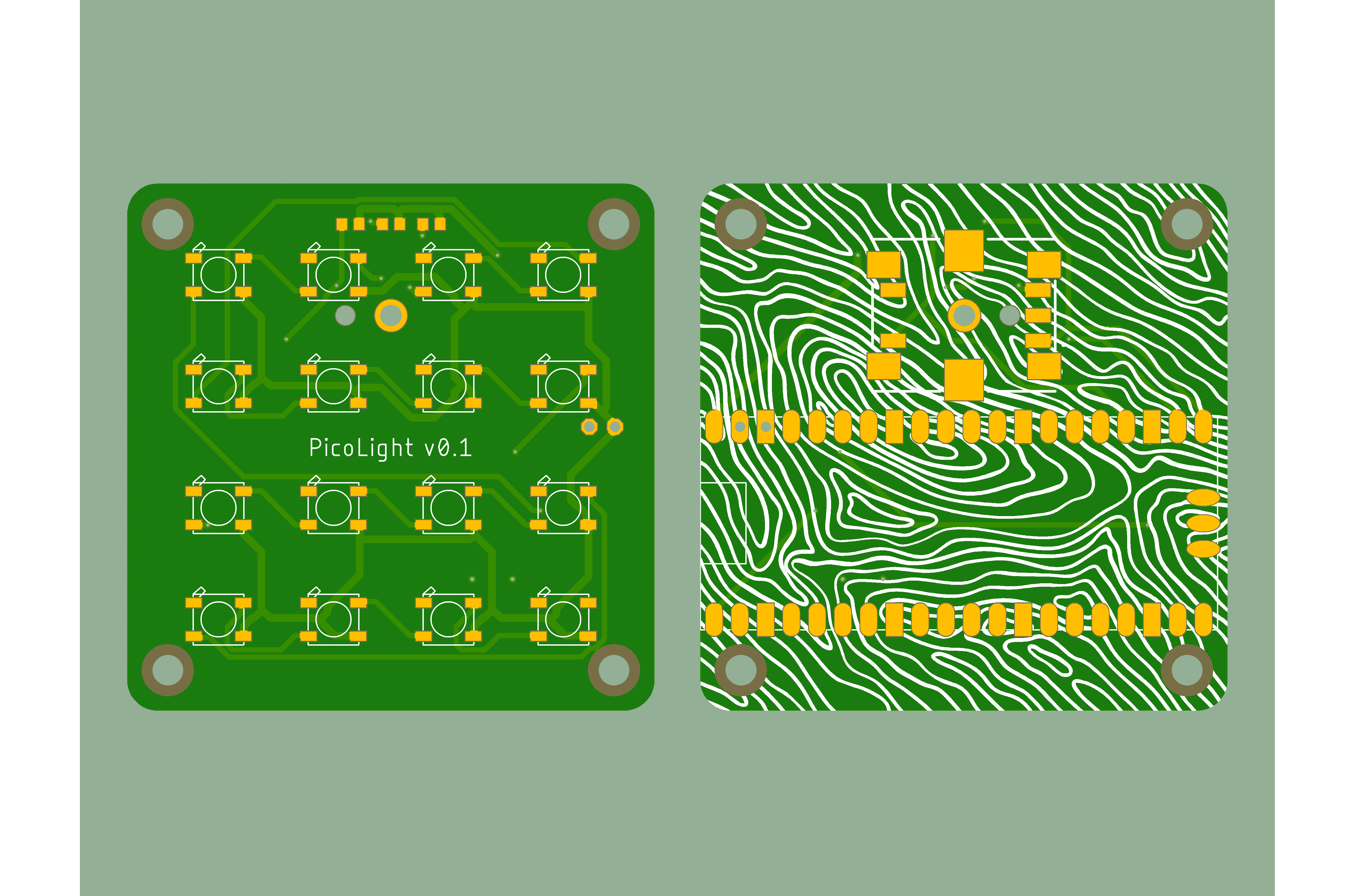
The Neopixel Matrix PCB is 52x52 mm with M3 slots for the standoffs meant to hold everything together. I've designed them in Eagle CAD using the SVG to Eagle converter by Gordon Williams to import custom images to the board.
I first tried to solder the WS2812B LEDs using a reflow oven, but the temperature was too high so I've burned them :(. On my second attempt, I've used Miniware's Mini Hot Plate, which worked much better.
Battery Shield
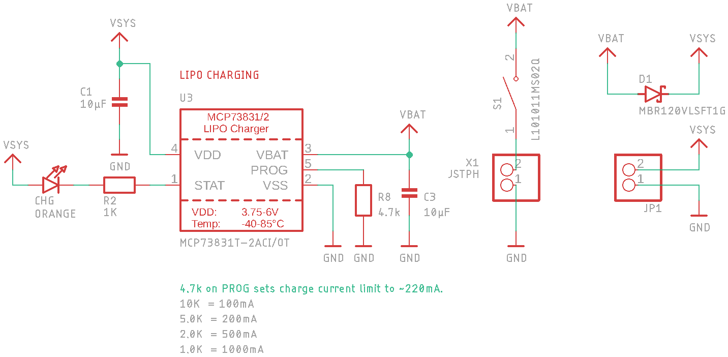
The battery shield includes a charging circuit based on the MCP73831T IC and I've used it with a 620 mAh LiPo battery. This shield plugs into the Neopixel matrix through a 2.54mm pitch pin header.
Programming
PicoLight was programmed in CircuitPython using Thonny, as suggested in this Adafruit tutorial. The push-button is used to switch between the three functioning modes:
- adjusting the intensity;
- adjusting the colour (looping through all available colours);
- rainbow cycle mode.
The values of the intensity and of the colour are stored in the data.txt file so the settings are kept even after PicoLight is rebooted.
What to use it for
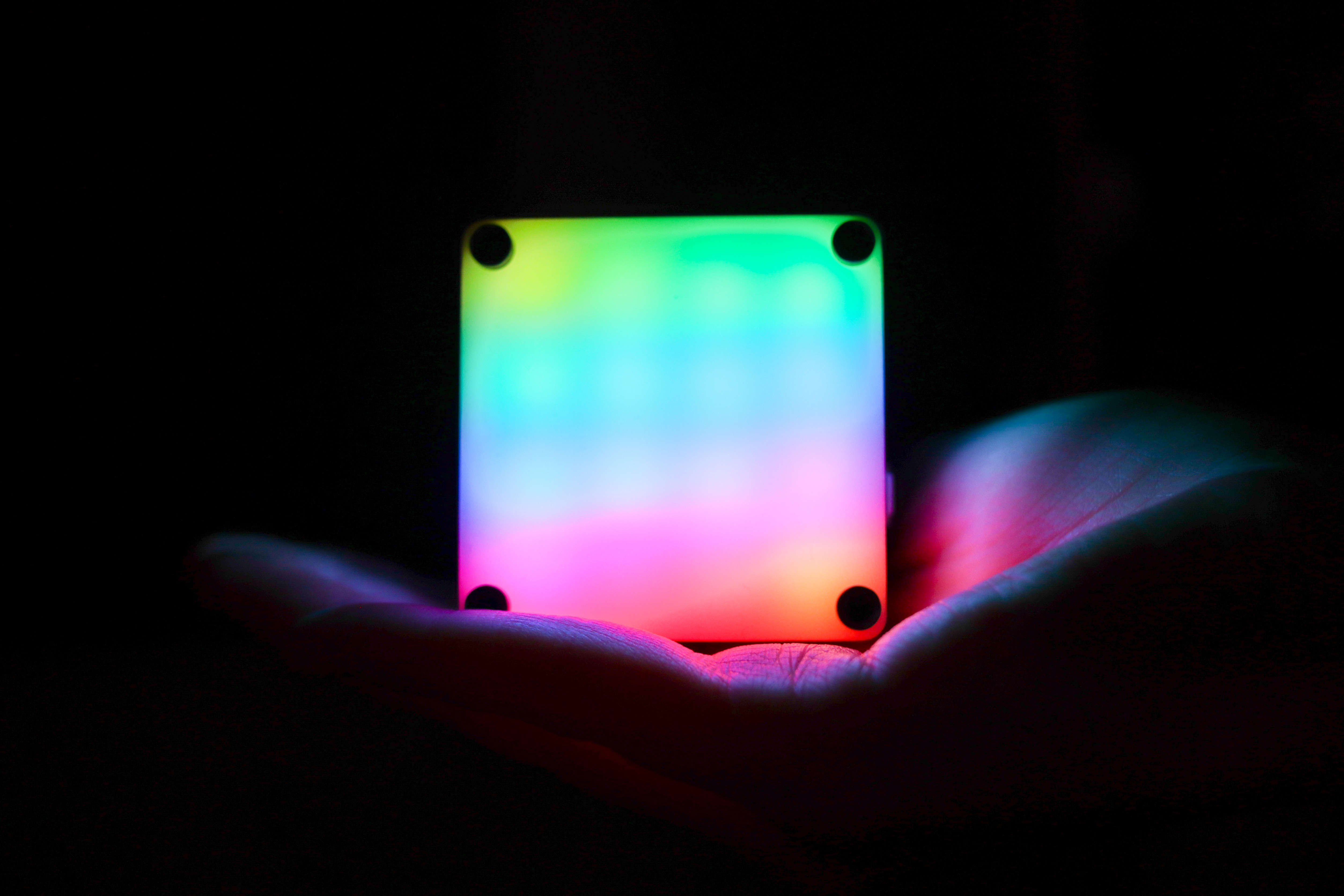
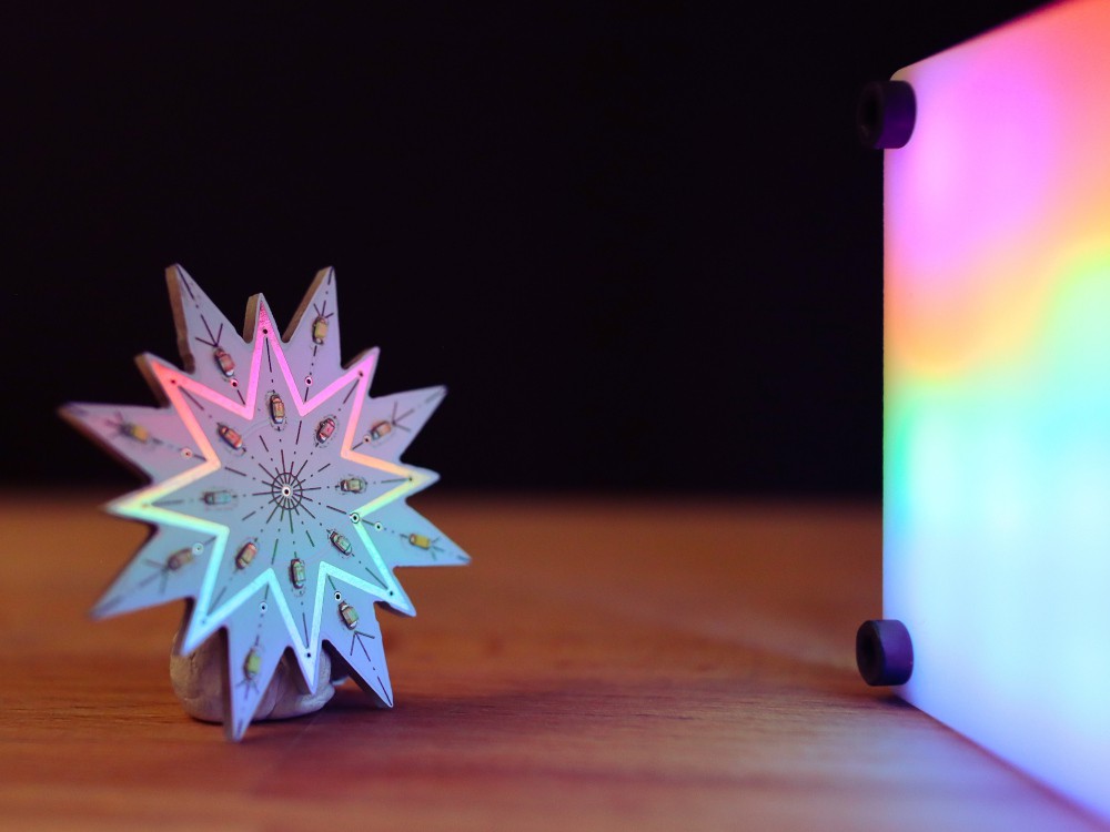
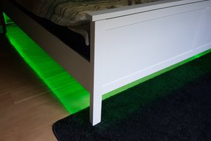
I've played a bit with different objects and here are some results:
 Zalmotek

 Niel Malan
 Pierre-Loup M.
 Heather-Lynne Van Wilde