 Zalmotek
-
1Order the PCBs and the stencil
Usually, before I order the PCBs I make sure I have all the necessary components. Otherwise, I need to find similar ones which may not have the same footprint and I have to update the PCBs as well.
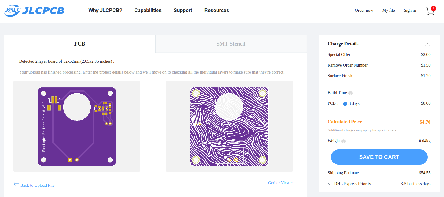
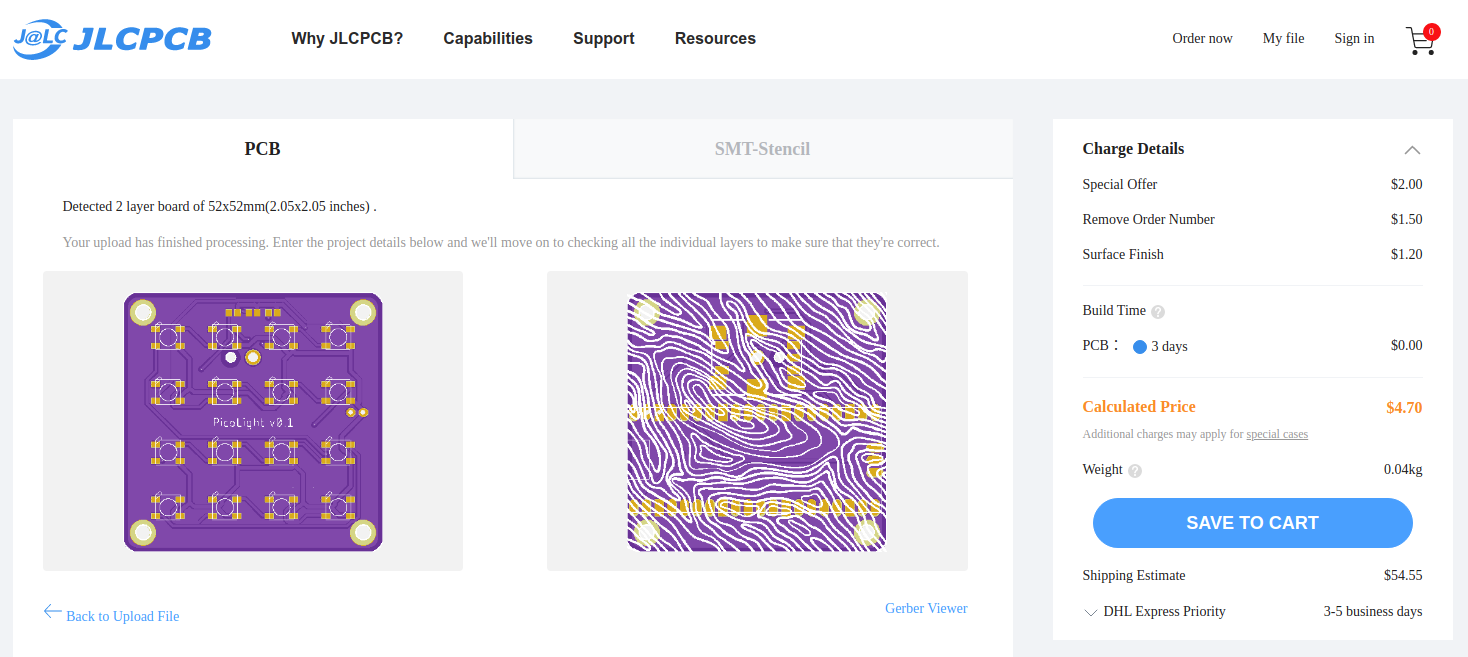
Go to jlcpcb.com or your PCB fab house of choice and upload the Gerber files for the LED matrix PCB and for the battery shield. You can find both in the Github repository of the project. Select the quantity, the soldermask color, the surface finish (I usually go with LeadFree HASL-RoHS or ENIG-RoHS), and check the Remove Order Number option.
![]()
![]()
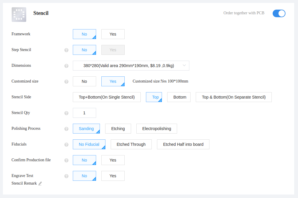
Then order the stencils: one for the LED matrix PCB and one for the battery shield. I selected a custom-size stencil (10x10 cm) since the default one is way too large to work with for such a small PCB. Plus, if you order a smaller stencil it gets shipped in the same box as the PCBs which is more convenient.
![]()
-
2Laser cut the acrylic panel
Order a laser-cut acrylic panel from your local fab house (or you can laser cut it yourself if you have the tools!). We've used semi-transparent white acrylic panels in order to diffuse the light. You can find the files in the Github repository.
-
3Solder the LEDs
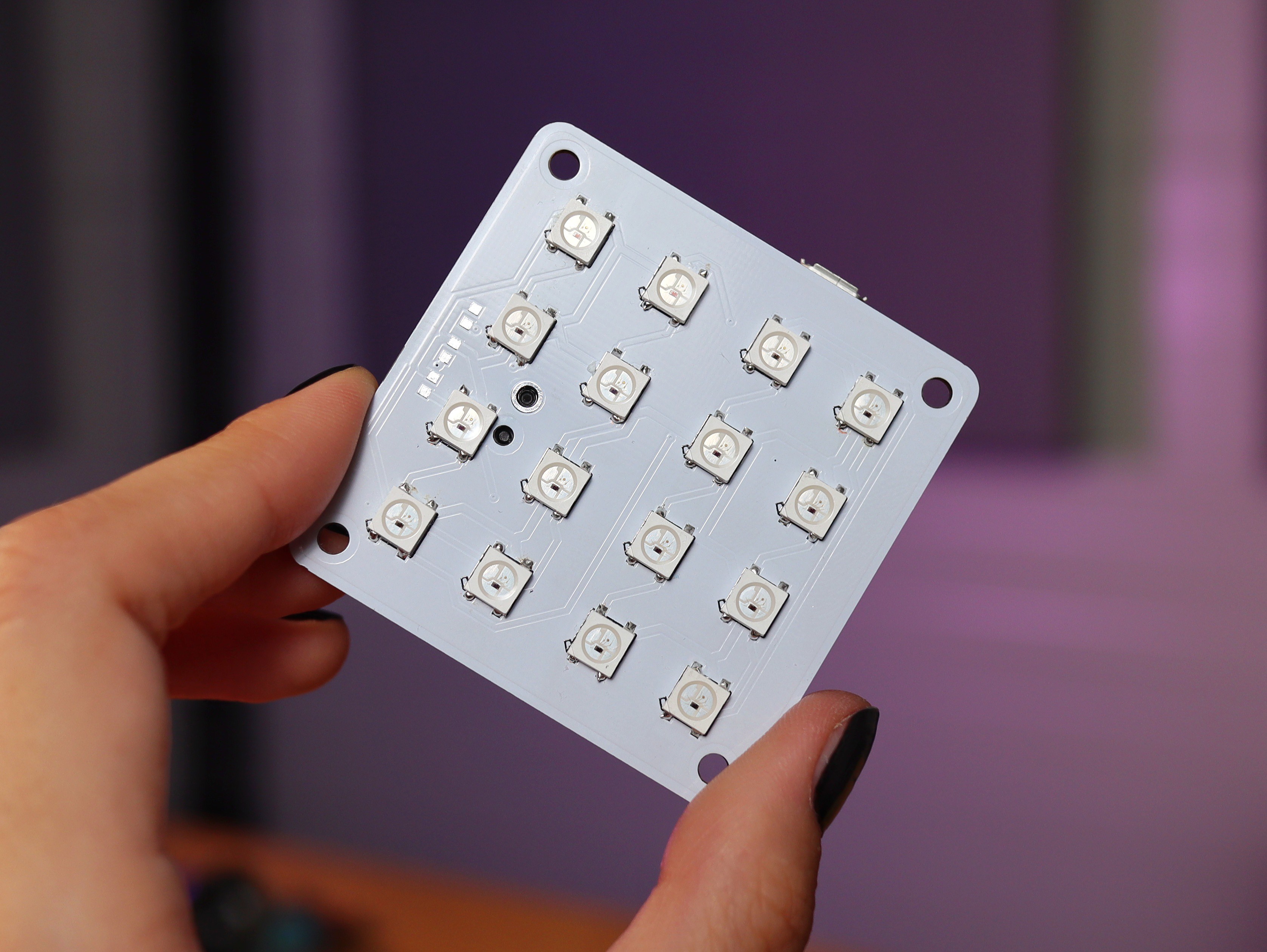
Start by soldering the LEDs onto the LED matrix PCB, using the stencil you've ordered. Make sure the LEDs are stored properly, in a low humidity environment, and that the temperature of the reflow oven is not too high for the LEDs. I recommend using a reflow oven if you have one, or this adorable mini hot plate from Miniware which you can get from Adafruit.
You may notice there are three empty pads for pull-up resistors for the encoder pins which you can use if you want to, but I chose to use the internet pull-up resistors of the Raspberry Pi Pico instead.
![]()
-
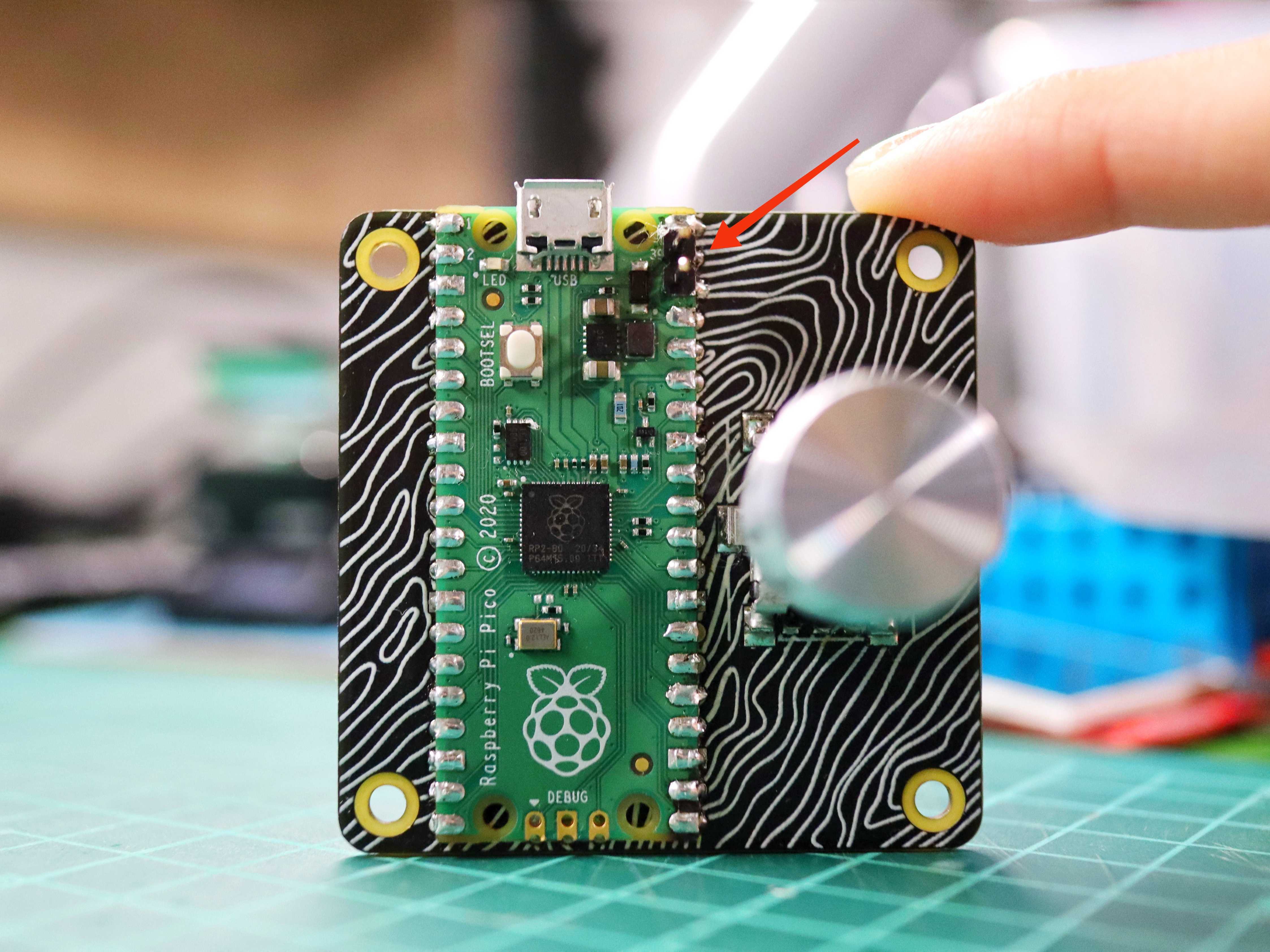
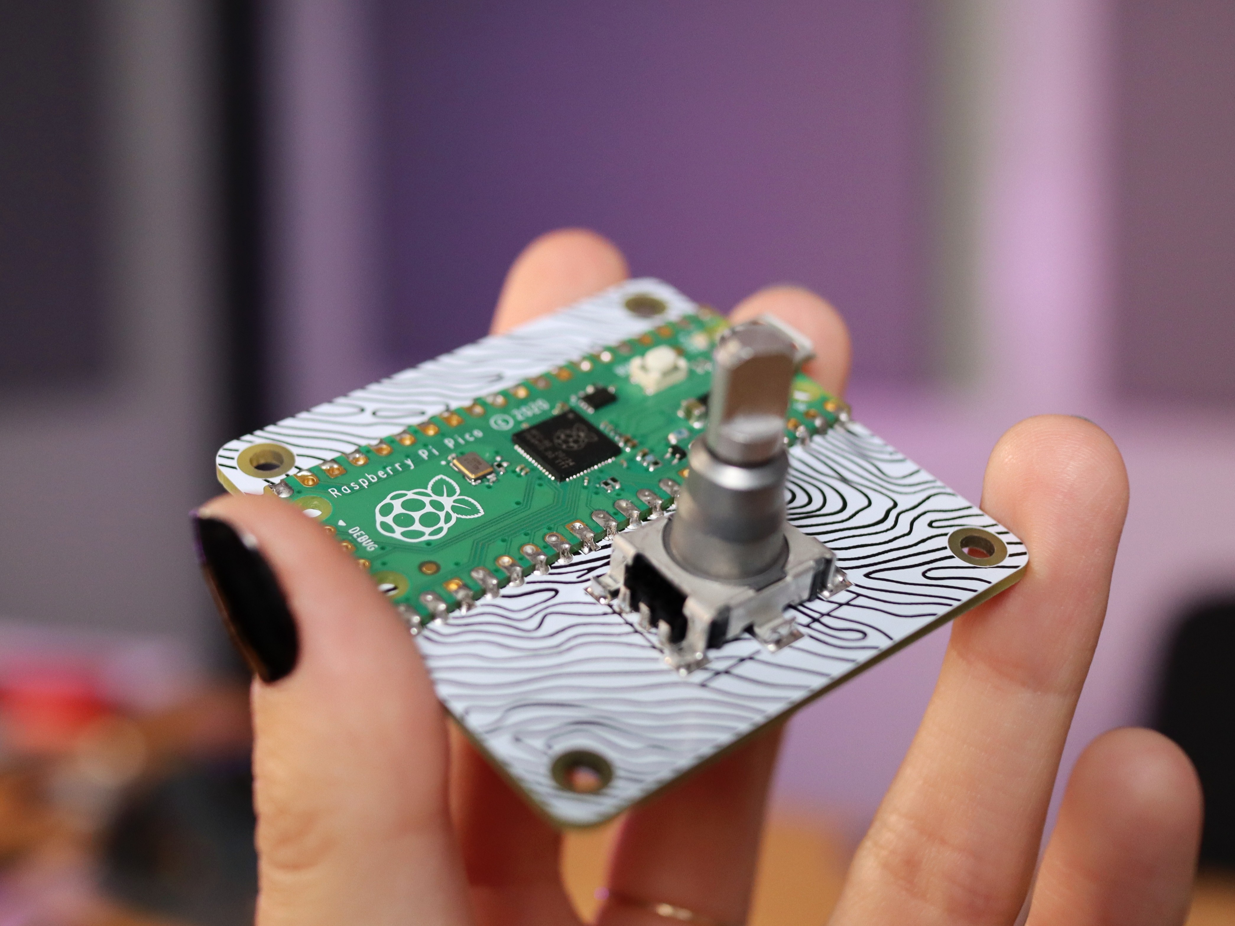
4Solder the Raspberry Pi Pico and the encoder
Next, solder the back of the LED matrix, using a soldering iron this time, in this order:
- place the Raspberry Pi Pico on the footprint
- place the 1x2 male pin header through the pin holes of the Pi Pico and through the PCB as pictured below (these pins will connect to the battery shield PCB)
- solder the Pi Pico pins
- solder the 1x2 male pin header on the other side of the PCB
- solder the encoder
![]()
![]()
* This last picture is the first prototype so the male pins for the battery connector are missing
-
5Solder the SMD battery shield components
Next solder the SMD components from the battery shield using the stencil and a hot plate/reflow oven.
-
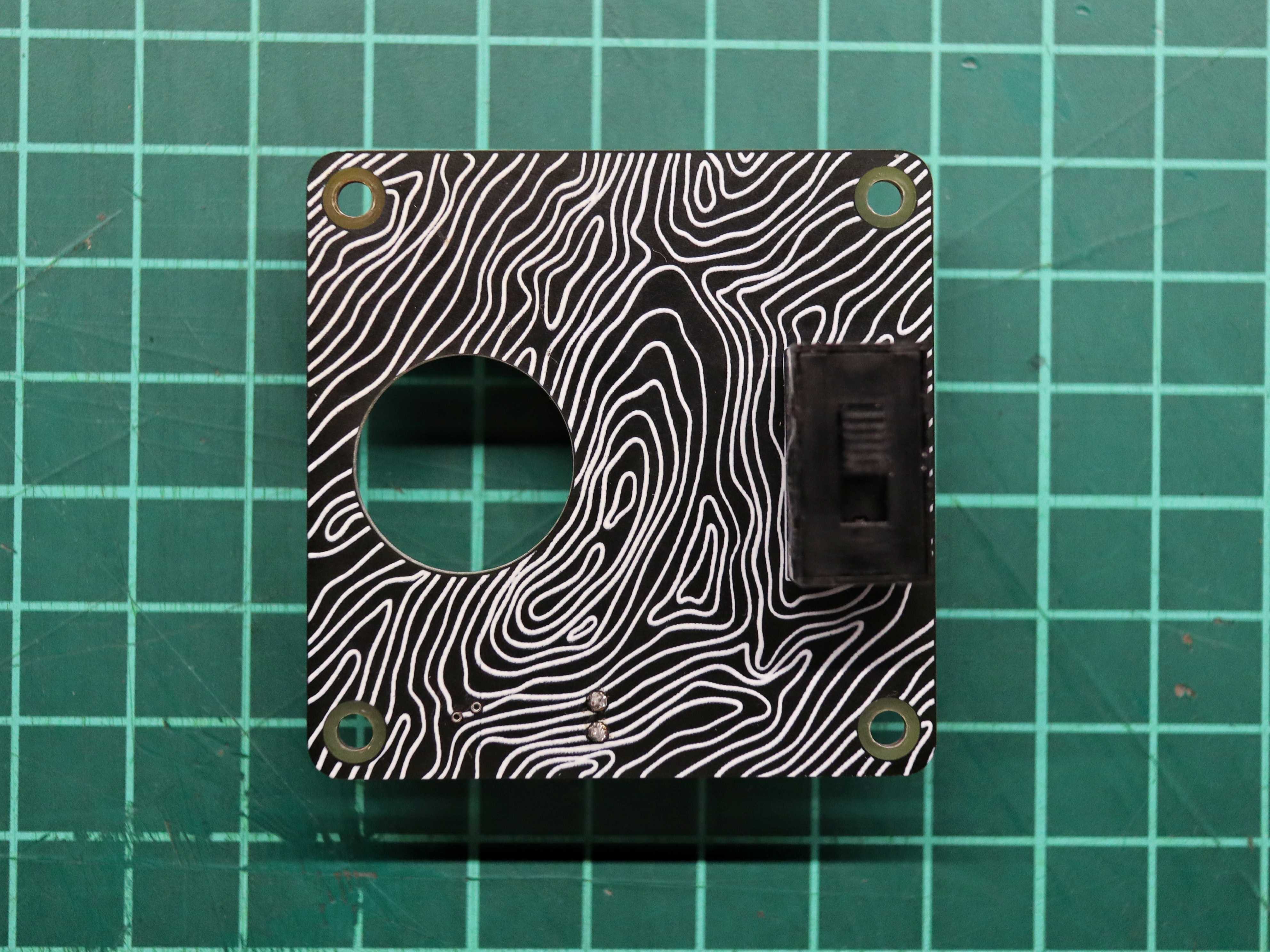
6Solder the THT battery shield components
Now solder the switch and the 1x2 female pins connector.
![]()
-
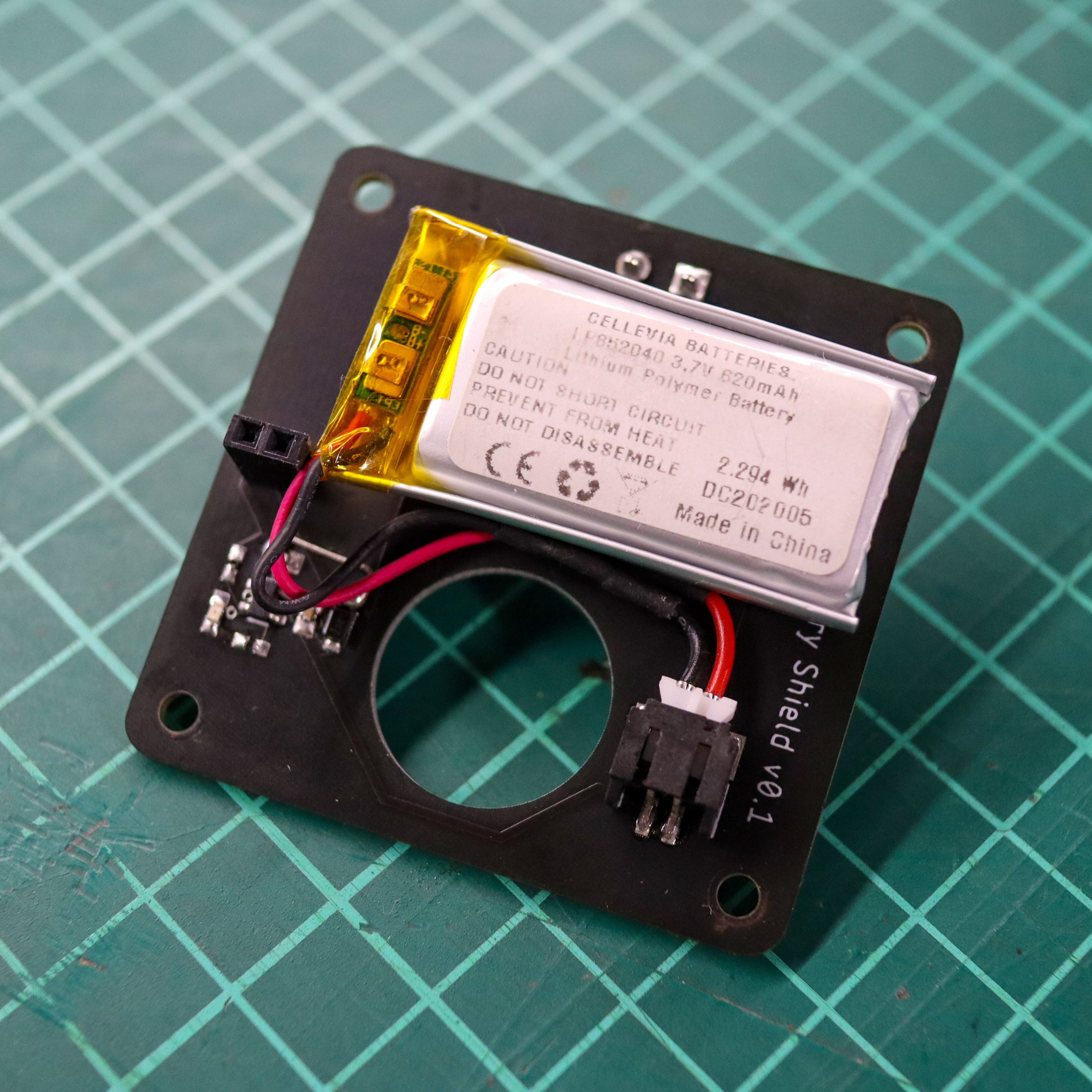
7Add the LiPo battery
Connect the LiPo battery to the shield and fix it using some double-sided adhesive tape.
![]()
-
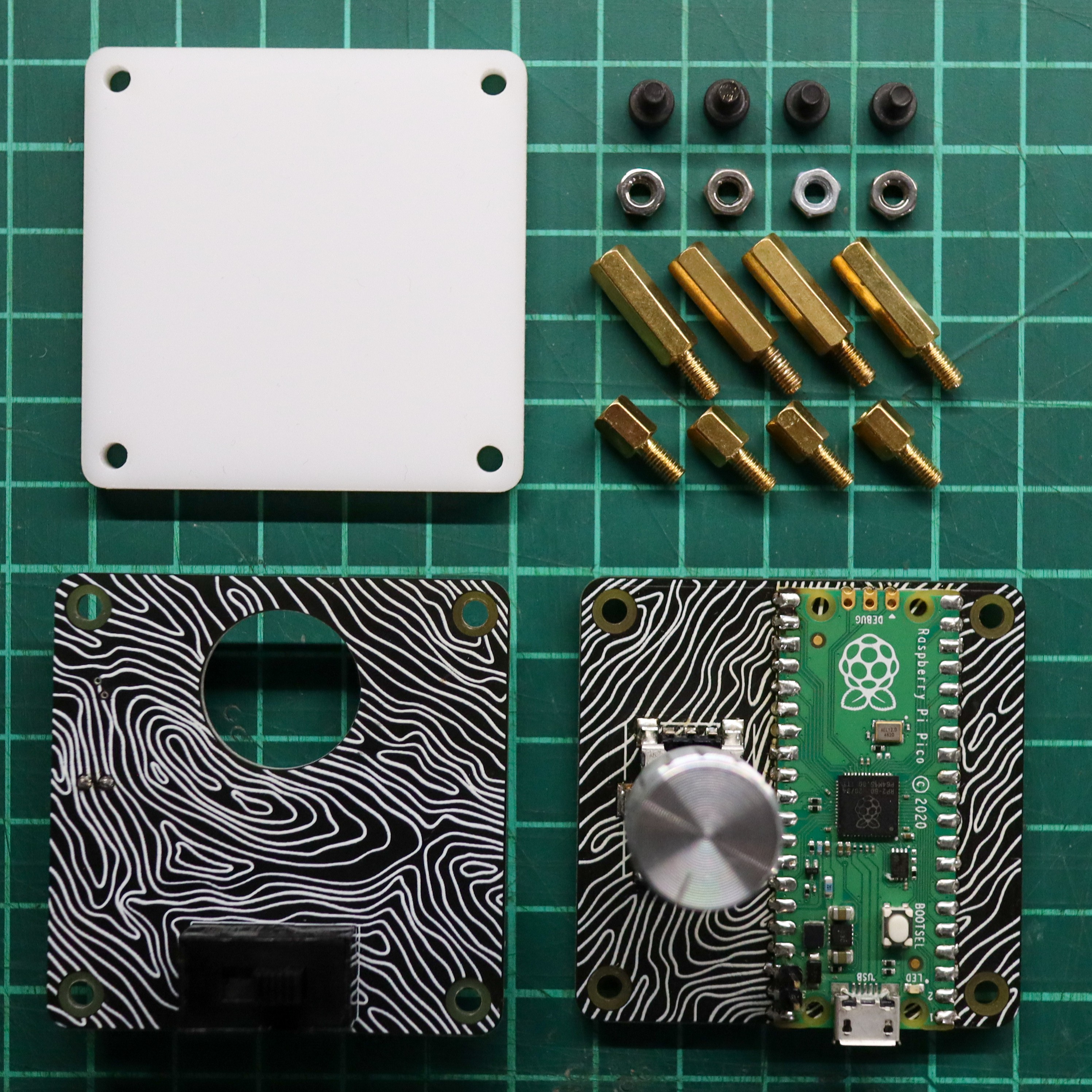
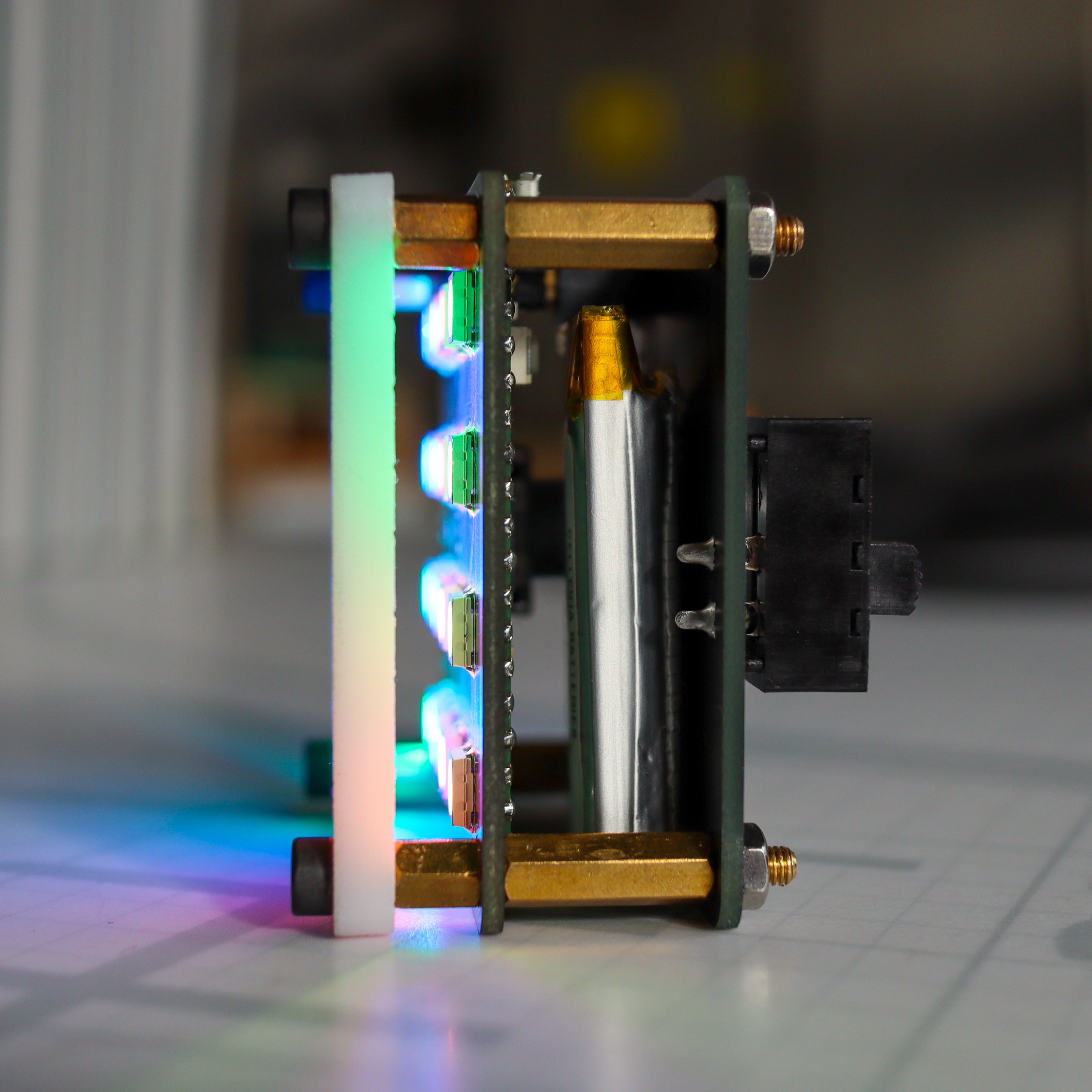
8Assemble the PicoLight
Now it's time to put them all together! First, screw the longer spacers to the battery shield using the nuts, and then connect the LED matrix to the battery shield through the pins you've just soldered (make sure they're properly aligned). Now screw the shorter spacers to the longer spacers through the LED matrix PCB and, finally, add the acrylic panel on top of that and fix it using the M3 screws. It should look something like the second picture.
![]()
![]()
-
9Program the PicoLight
You can program the PicoLight using Thonny or any other Circuit Python editor you prefer. Simply upload all the files in the circuit python folder from the Github repository of the project to the Pi Pico.
-
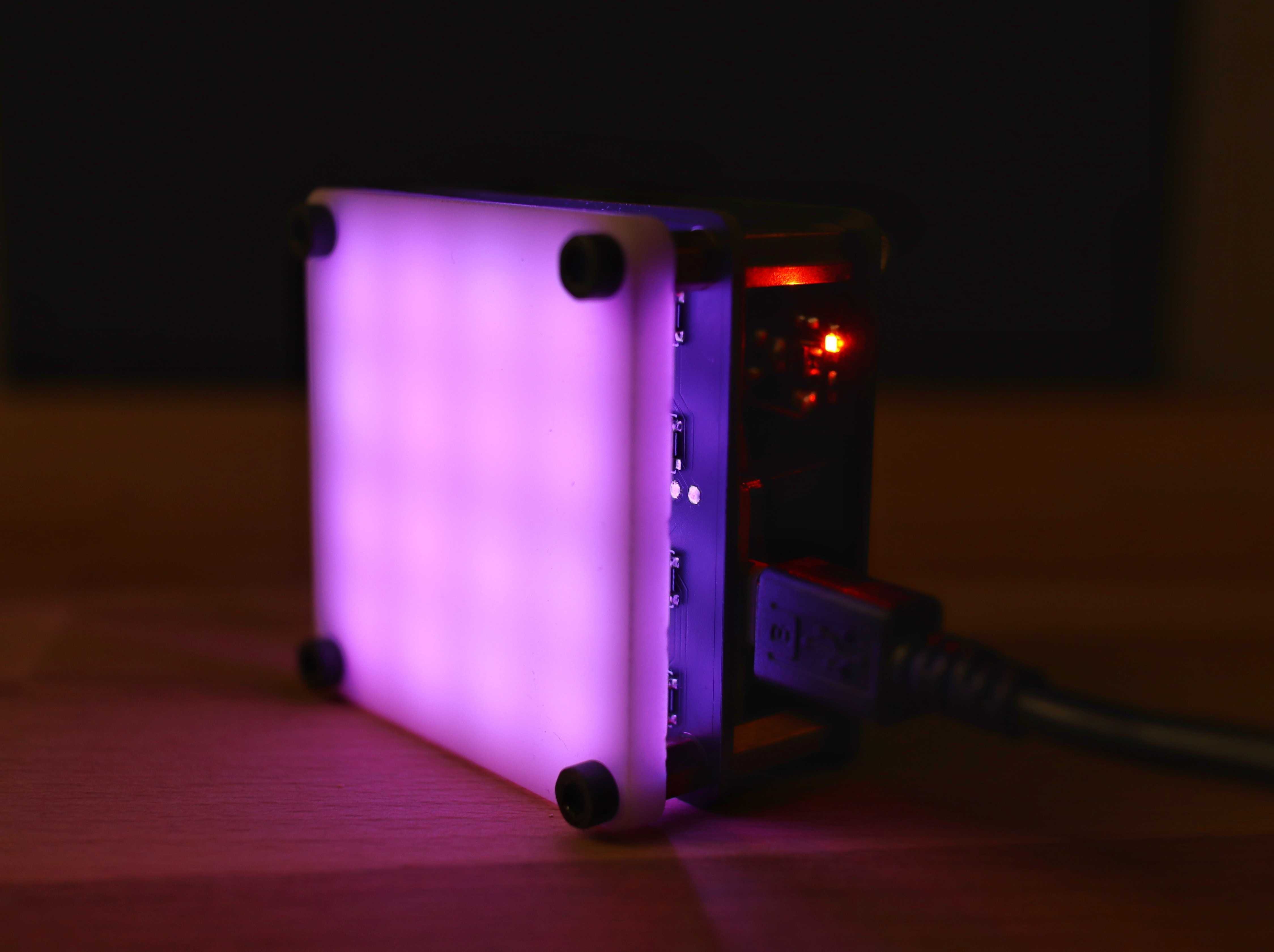
10Charge the PicoLight
Connect the PicoLight to the micro USB and you'll see the charging LED on. If the LED is not on, then turn on the switch from the back of the PicoLight.
![]()
PicoLight - Minimalist Light for Product Shots
PicoLight is a minimalist adjustable light for low-light photography, based on the Raspberry Pi Pico.
Discussions
Become a Hackaday.io Member
Create an account to leave a comment. Already have an account? Log In.