David
David-
Testing the bus cable
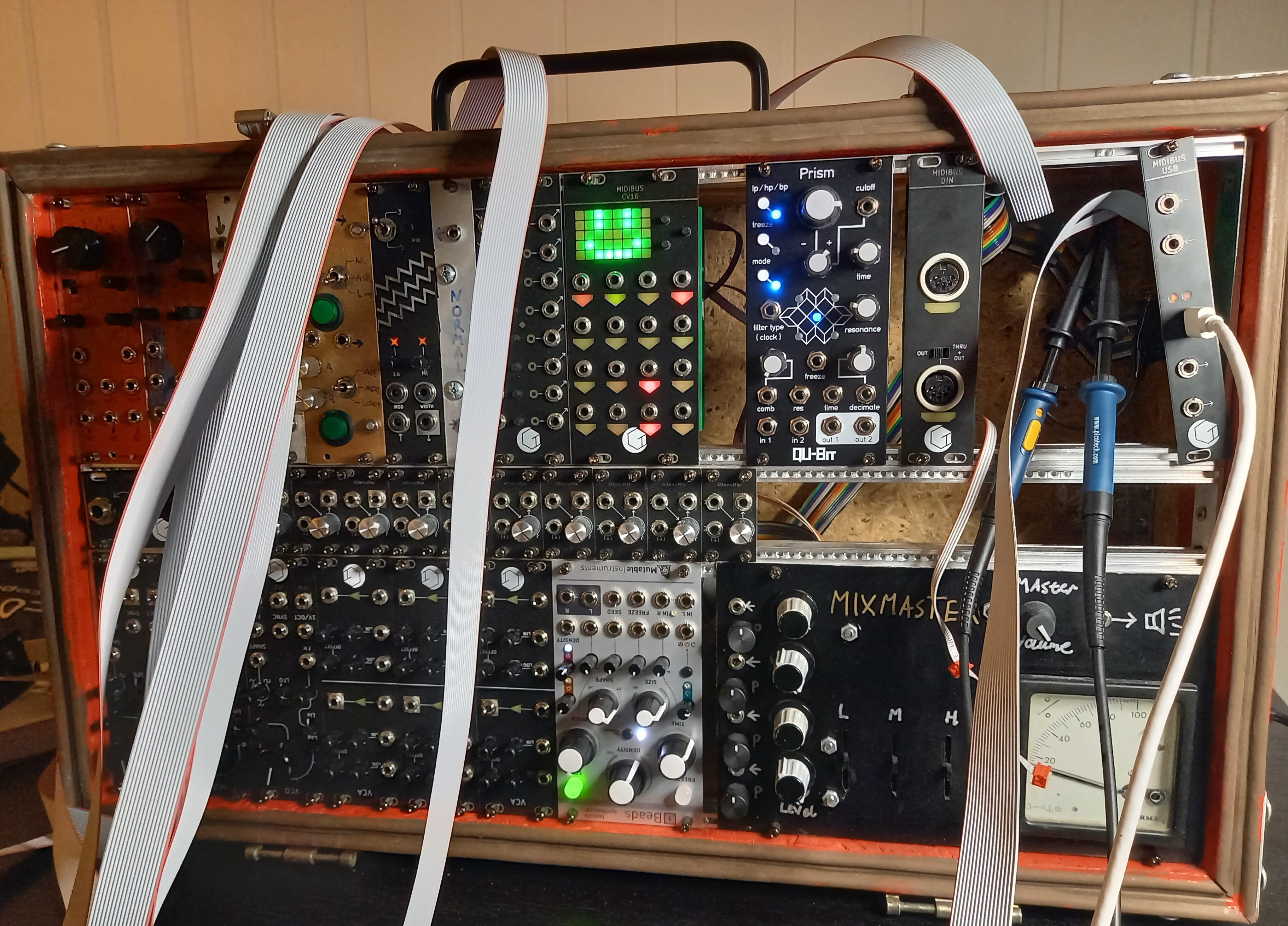
03/15/2023 at 17:32 • 0 commentsLong time no write, life got busy for a while. Anyway, I've been taking a closer look at the CAN bus used in this system. I have earlier guesstimated the performance of the bus, and I wanted to verify that it's going to work well. The tests I have performed so far look promising from what I can tell.
![]()
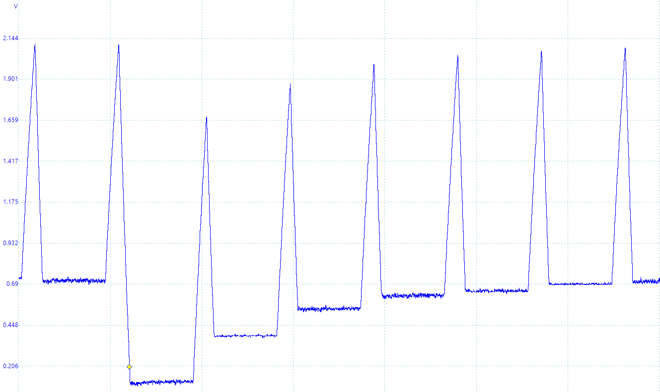
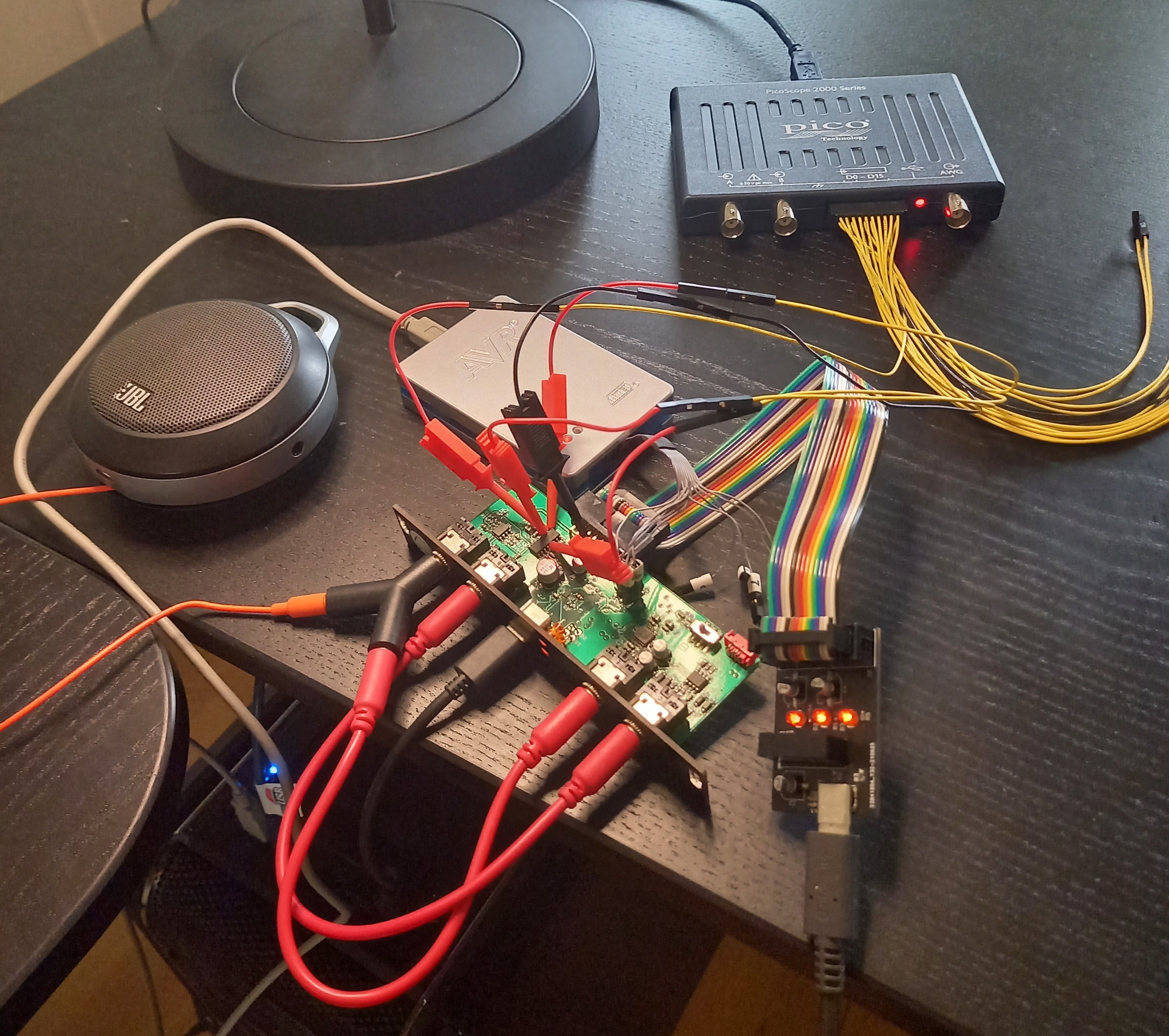
First I tested the bus with a 10m cable, a cable of that length would cover the vast majority of modular setups. A 16-pin cable was used because it was almost the same cost as a 4-pin cable, and I can use this one to make power cables later. My biggest concern with this test was reflections of signals on the bus, but to my surprise, I could not find any. The cable has a propagation time of 4.9ns/m which means the signal can make 10 roundtrips during a single transferred bit, this gives it a lot of time to settle.
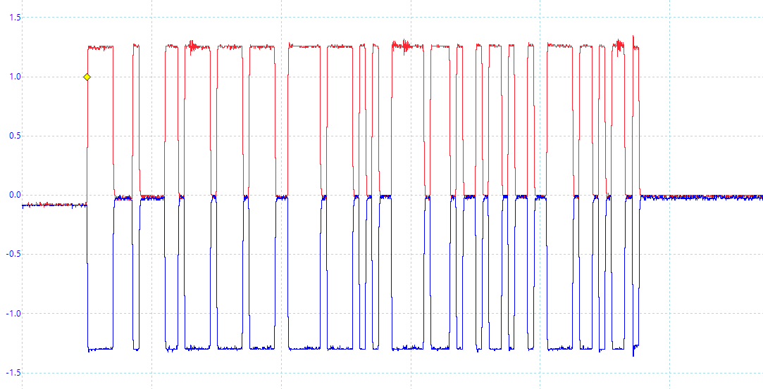
Initial measurement:![]()
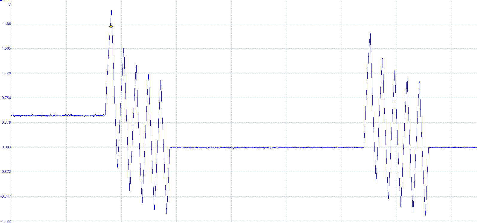
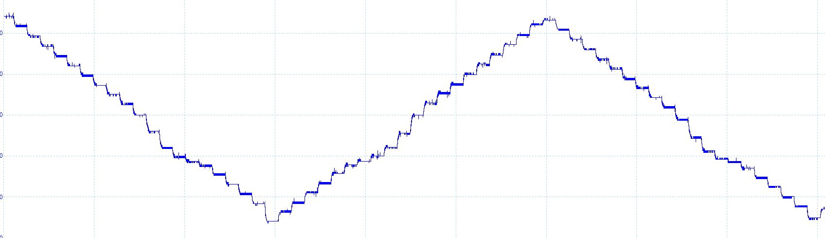
The termination resistance was initially wrong due to a (mis?)calculation of the cable's impedance. It didn't look like it caused any issues, but 240 ohm is outside the ISO spec. Reducing the termination to 120 ohm reduced the signal amplitudes to +-1V which is nominal for CAN.
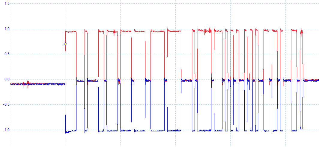
120 ohm measurement:
![]()
The measurements show some differential noise, which moved to the other probe when the ground clip was switched. So that may be ground bounce from some digital circuit, or possibly from the USB connection. This would probably not be there if the oscilloscope wasn't attached.
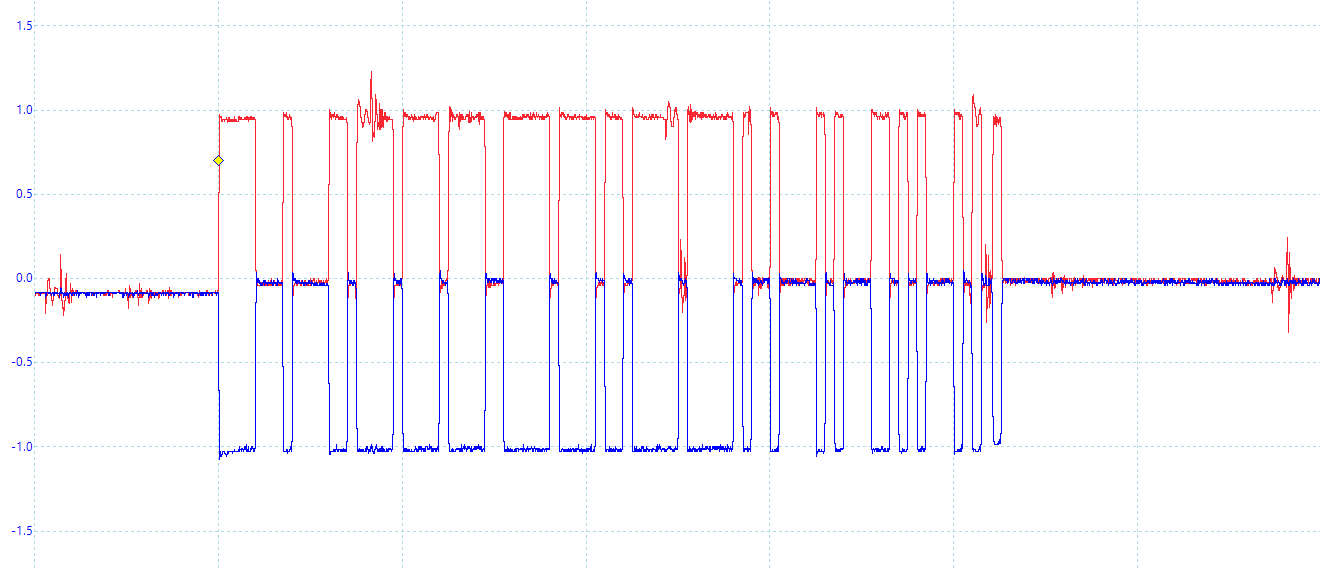
Differential noise:
![]()
Far-field emission will likely not be an issue, a 75m-100m long bus cable would be needed to form a half-wave dipole. It could still form a short dipole though, but as far as I understand it would only be an issue if one end of the bus has a high impedance. This could happen if someone forgets to connect the termination resistance, but that would be a user error, not an issue with the bus.
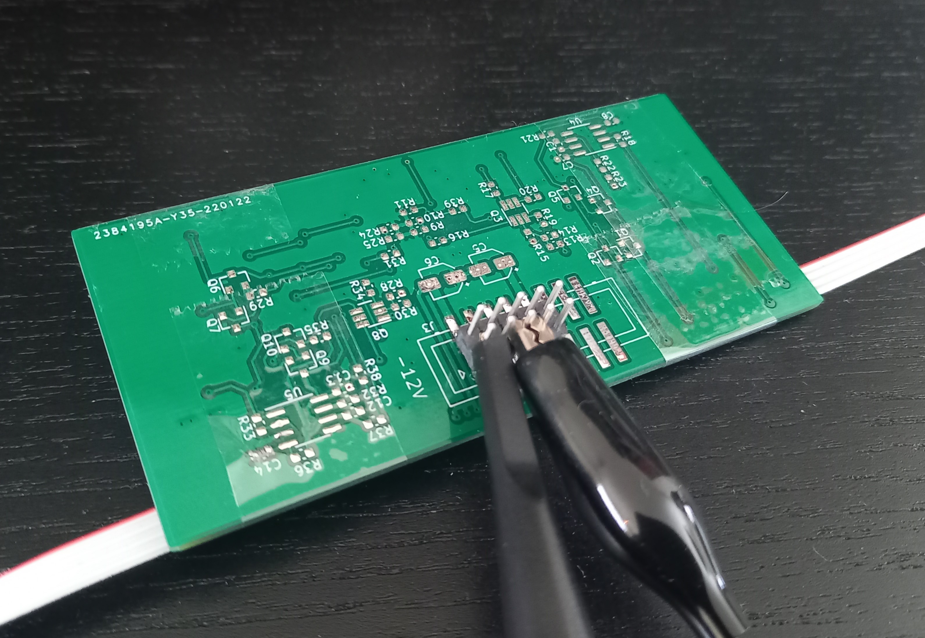
The next test was measuring the near-field emissions since the cable will be in close proximity to many other modules. I was considering getting a near-field probe for this, but I wouldn't know how to interpret those results. I imagine one of the worse situations that could occur is the bus laying in parallel with a long high-impedance trace on a module. So I grabbed one of the PCBs I had from old prototypes, found a long trace (~66mm), soldered a 1 Mohm resistance to ground, and taped the bus cable along this trace.
The test setup:
![]()
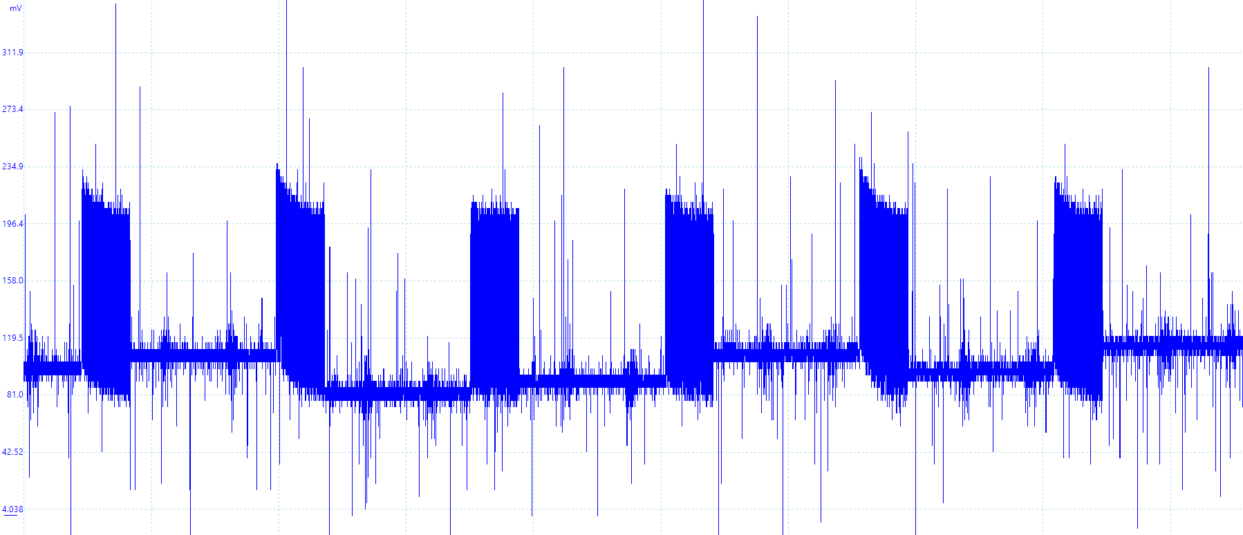
The signals measured on this trace had an amplitude of 10mV, which would be 0.1% of a typical analog signal in eurorack. I would say that's pretty good for a worse-case scenario.
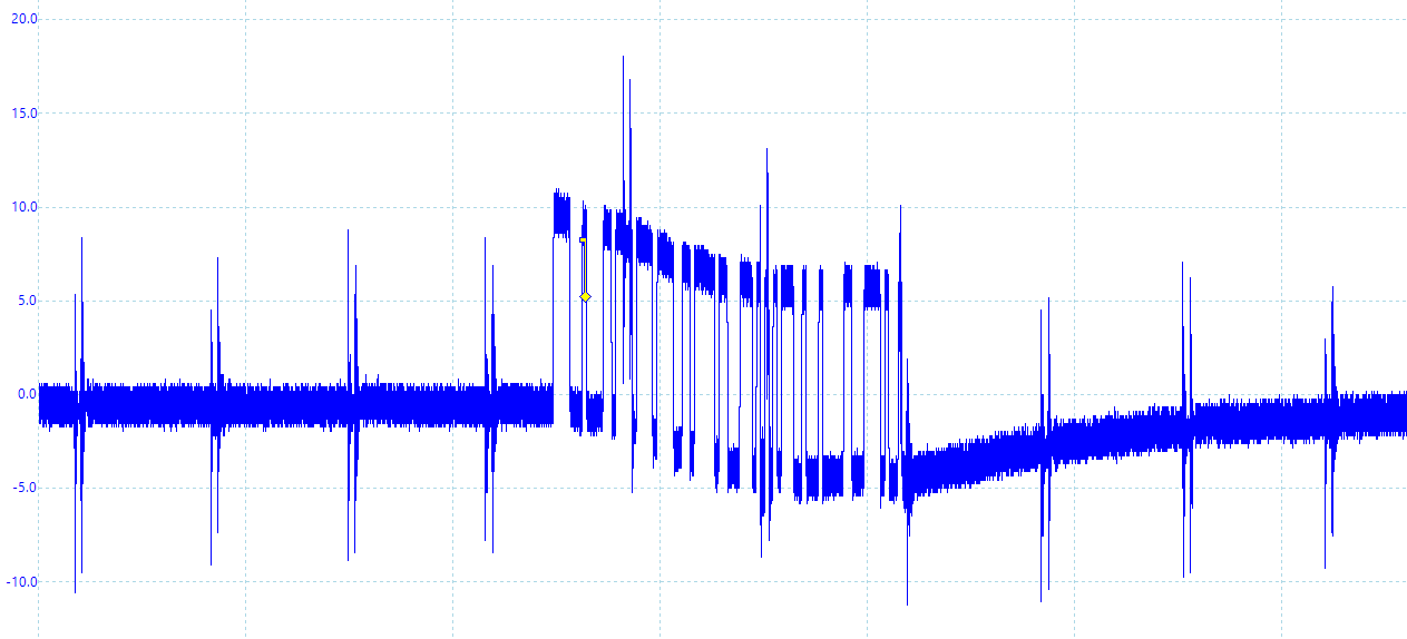
Radiated signal:
![]()
Moving on to the connectors, there is one important property I've overlooked: the number of mating cycles. The connectors I have are only rated for 25 mating cycles, and the springy part is on the PCB. The bus connection is not supposed to be disconnected and reconnected often, but it would still suck having to de-solder the connector if it wears out. It seems like the manufacturers are giving a low estimate though, I tried 100 cycles on a connector and don't notice a difference in its strength. I haven't found a great alternative for 4-pin IDC connectors, so I will keep using these.
I also want to utilize more of the built-in features of the CAN controllers. These controllers have hardware filtering of message IDs, it would be a shame not using that at all. But the message ID is also used for arbitration so some of it must be random to prevent message collisions. Message type and midi group would be good candidates for filtering, but using both in the ID would let the bus support only 8 modules. I will probably put the message type in the ID field and leave the rest random. This will let a module filter out message types it doesn't use (like sysex), so the MCU won't be interrupted when they are sent over the bus.
One of the big features of CAN FD is the flexible data rate, allowing the payload to be sent at a higher data rate to increase data bandwidth. This increased data rate must be configured in every node before it can be used, otherwise, the nodes will misread the data. So, I have specified time segments for 4 Mbps. The frame header will still be 1 Mbps, so the gains are greater for bigger payloads.
Speaking of bigger payloads, we could send more than one MIDI packet in the same CAN frame. This wouldn't make sense for most message types as we want low latency. But data/sysex messages can consist of several MIDI packets, which would make sense to send together. This takes up more memory per message in the buffers, but a module can filter out these message types to save memory if they're not used.
Finally, I have also updated the driver for the CAN controller to make it easier to port for other MCUs. Have only implemented it in the USB module so far.
With all of that out of the way, it may actually be time to start revising the PCBs.
-
First demo
11/22/2022 at 20:31 • 0 commentsI have performed some debugging since the previous log, and have finally recorded a demo. The nonlinearity of the CV module makes it impossible to keep the oscillators in tune, but this is good enough for now.
The stuck MIDI notes I mentioned in the last log were caused by lost packets in the USB module. Which happened because the USB driver uses a bulk endpoint, and the transition to the CAN bus was not buffered. I added a buffer to make sure all packets are sent to the internal bus, which improved it. I have still noticed some issues with high throughput, so that's something to investigate further.
The I2S connection had a couple of problems, the left and right channels were constantly swapping and the sample rate was slightly wrong. I ended up fixing the sample rate by implementing a simple
PID regulator to adjust the frequency generated by the PLL. The Tx direction regulates the rate by aiming for a set number of samples in the buffer, this lets the USB host dictate the rate of samples while still tolerating some errors. The Rx direction can't do that because the USB driver can send extra samples in a frame, so it uses a running average of the number of samples sent in a frame. The module uses the same clock for both Rx and Tx, so the Tx takes care of regulation when both are enabled. This probably won't settle completely due to jitter in the USB frames, and it still has some stutters, but it is much better.Trying to fix the audio channel swapping was very annoying. It seems like there only is a problem when the DMA stops, so regulating the sample rate helps during normal operation. It can still encounter fetch errors or stop when the audio stream is turned off. The current solution is to check the word select signal when a DMA block is completed and suspend it if it's wrong. Then restart it on the next positive edge. This solution is not perfect but seems to self-correct most of the time.
A new revision of the PCBs is getting near now, then I can finally fix the hardware issues. But before that, I want to look closer at the CAN bus. -
CV module improvements and issues
09/18/2022 at 20:30 • 0 commentsSince the last update, I have been working on the CV module. Its firmware is starting to become functional, the menu can now edit the configuration and it reacts correctly to most MIDI messages. But, it still needs a lot of refining. The support for paraphonic configurations has given me some challenges as I want the module to auto-detect which outputs are shared.
I changed the LEDs because I thought they were too dim, now they are super bright green ones. When they were first installed the LEDs were all shining, likely these LEDs require less current to turn on so they shine from the leakage when transistors are turned off. So I had to change the firmware to skip disabled LEDs, which give varying brightness and flicker depending on the number of LEDs that are on. It still bleeds a bit at max brightness, but it is good enough.
![]()
![]()
When testing the outputs I found that they had an unintended vibrato/frequency modulation. Investigating further I found that the output had 1V of ripple, resulting in an octave change in the VCO. It also showed that the multiplexer was switching a lot faster than intended.
![]()
This is what it first looked like, a single spike in the sampling period. It also seems to settle on a random voltage, since it sometimes dips by half a volt. This can also be heard when it is used. Fixing the MUX rate gave the following:
![]()
It still has the same amount of ripple, and the voltage it settles on is still random.
![]()
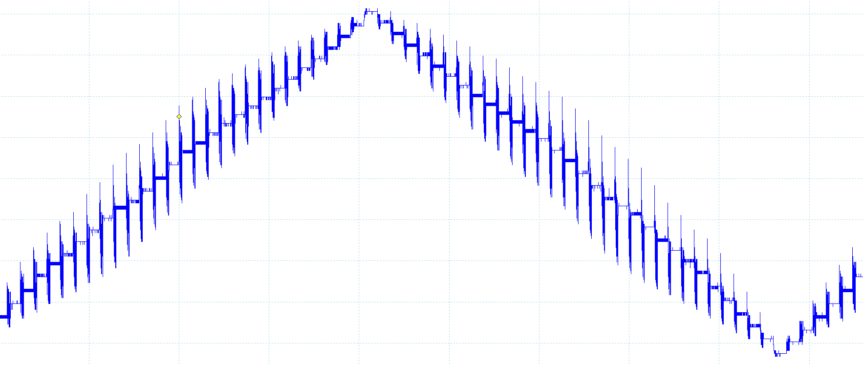
This is what a 0.5Hz triangle wave currently looks like from this module.
Reducing the PWM resolution from 16 bits to 12 bits improves the results. This increases the PWM frequency so it is more attenuated by the filter. Alternate solutions could be lowering the filter cutoff, which also reduces how fast the voltage can change. Another option is using a higher-order filter, but this would increase the circuit complexity.
![]()
The ripple is now 160mV or so.
![]()
The triangle wave looks cleaner as well, but there is some non-linearity.
I recorded a clip so you can hear what it sounds like, in the video below. You can hear that the VCO goes out of tune in the last test, which is probably caused by the non-linearity seen above. But there is also an amplification stage which likely is inaccurate. I believe I intended to fix that in the firmware.
To conclude, using a multiplexer as a sample and hold works great, the voltage is really stable in the hold period. Using filtered PWM does not work as well, it naturally gives some ripple no matter how well it's filtered. And better filtering will either need higher complexity circuits, lower resolution, or slower output signals. Problem is that whenever it is used to control pitch it will be very noticeable. Changing to DACs might be a good idea for this. The only issue with that is they're expensive and currently hard to acquire, so I will keep the multiplexing to reduce the number needed.
My current goal is to record a demonstration video, but I'm having problems with notes getting stuck. This can be caused by many things: lost messages, a bug in the CV module firmware, or maybe a problem with the program used to play the MIDI file. I will likely try to fix that next.
-
Project update
07/25/2022 at 11:32 • 0 commentsI have been making some progress this past month, mostly on the USB module. I'm trying to verify the current hardware before doing another revision of the PCBs. So I also got the SAM-BA bootloader from Microchip working on one of the modules.
For the USB stack I ended up using the TinyUSB library because it has both audio and MIDI device drivers ready. It took a while to get it working even with the library, but it is now mostly working in device mode. I have some issues with the audio streaming, the left and right channels are constantly switching and the sample rate is too fast. The channel switching is probably a firmware issue, it is quite annoying as it degrades the audio quality. I have tried using separate DMA channels for each audio channel and checking the word select signal, to no avail. The fast sample rate is caused by an inaccuracy of the internal oscillator, so that's another reason to add an external crystal.
I also made a fork of the library to attempt implementing host mode on the SAMD21 controller. Luckily the library handles all the high-level USB stuff, and "only" a set of functions must be defined to let it interface with the hardware. I got it partially working with the host hid_example. When the PS4 controller is directly connected to the MCU it works, but if it is connected via a USB hub the device will stall forever. The code also gets stuck in a wait function occasionally because the frame number does not increment when no device is connected, but it can recover from this state. My fork is currently limited to 8 endpoints, but the SAMD21 supports virtual pipes to increase this. I will probably implement this later. The host stack is apparently a work in progress, so I will wait a bit to see if it improves.
![]()
This was the peak debugging setup. Picoscope to probe the physical I2S signals, In-circuit debugger to read internal data. A loopback connection from DAC to ADC and a speaker on one of the channels.
Next, I will probably improve the firmware of the CV module.
-
MIDI A2B
07/25/2022 at 10:57 • 0 commentsDuring my break from this project, the MIDI association announced a new transport supporting MIDI 2.0. The A2B bus is capable of transferring multiple channels of audio over a single UTP cable while also delivering power and additional data. This is interesting because it could replace the CAN bus used in this project while also providing audio streaming between nodes.
The full specs of this transport have not been published as I'm writing this, so some things are unclear. The announcement says a maximum of 17 nodes are supported with sub-buses, is that a hard limit? Can a sub-bus have sub-buses? The MIDI announcement says SPI will be used for MIDI, but none of the A2B transceivers have an SPI interface.
Anyway, I will continue using the CAN bus at least until the A2B transport is better defined.
-
Current state of the project
02/18/2022 at 21:17 • 0 commentsThis project was originally intended as an entry in the 2021 hackaday Designlab contest. It was totally too ambitious, given that university was taking up most of my time. I am currently working on (or procrastinating from) my master's thesis, so I won't have time to continue this project until July. But I want to put it out there, even in its current state. Unfortunately I haven't made any demo of the modules yet.
I do feel like the name is a bit too generic, since people may refer to any MIDI connection as a "MIDI bus". Also, there are a couple other projects with the name. Maybe the name should be changed to CAN-MIDI, or Modular MIDI (M2IDI), or something else.
Firmware status:
The code is a mess. And I have not used a bootloader so far, because the bootloaders need a button to activate.
CV module: Turns out programming flexible firmware is difficult, so the menu does not work yet. But most of the other features are present to some degree.
USB module: I have not found a perfect USB driver, and the notion of writing a driver is intimidating. This firmware has practically not been started.
DIN and Tangle: Are mostly done.
MIDI driver: MIDI 1.0 and 2.0 parsing is implemented, as well as conversion between these formats. However, their compliance with the standard should be double checked. Other features like capability exchange are not implemented.
Hardware status:
A couple issues were found after the PCBs were ordered. These should be mentioned in the CADLab annotations.
The USB-C connector's footprint was not within the capabilities of the PCB fabricator, so I had to reduce hole sizes. This means they are a bit tight. They also require thinner (1.2mm or less) PCBs to be soldered properly. I will probably change these to connectors with SMD pins for data and power, and through-hole for the shield to help with mechanical strength.
I discovered that the ATSAMD21G MCUs don't have an integrated EEPROM, they have flash as emulated EEPROM. Which isn't ideal, so I will likely add an external chip to save settings in.
The MIDI out on the DIN module does not work because its signal is inverted. This happened because the MCU I used in the previous version (Attiny406) could invert any pin's function from the firmware.
According to the ATSAMD21G datasheet its internal oscillator has too much jitter to be used in a (compliant) USB host, and it's recommended for USB devices as well. So it will need an external crystal. I should have discovered this before ordering the PCBs, it was in the schematic checklist.
The USB module has decent DACs and ADCs which in some situations wouldn't be used as an audio interface. It can be cool to add more RAM to this module so it can be used for delay and reverb effects if people want.
-
Module #4 - USB
10/15/2021 at 15:51 • 0 commentsThe USB module will provide a gateway between the USB MIDI transport and the CAN bus. Which means it needs to support both MIDI 1.0 and 2.0 over USB. This module also has an ADC and a DAC, both having 24-bits resolution and two channels for stereo. This let's it act as an audio interface so audio can be sent between the modular and a DAW. The schematics and PCBs can be viewed on CADLab.
This module can act both as a USB device, and as a host. There is a TUSB320 chip handling the USB-C direction logic, so the microcontroller behaves like a USB-OTG device. Devices connected to the port can draw up to 500mA, otherwise a powered hub would be needed.
![]()
The top-side contains mostly analog circuits, like the opamps, ADC, and DAC.
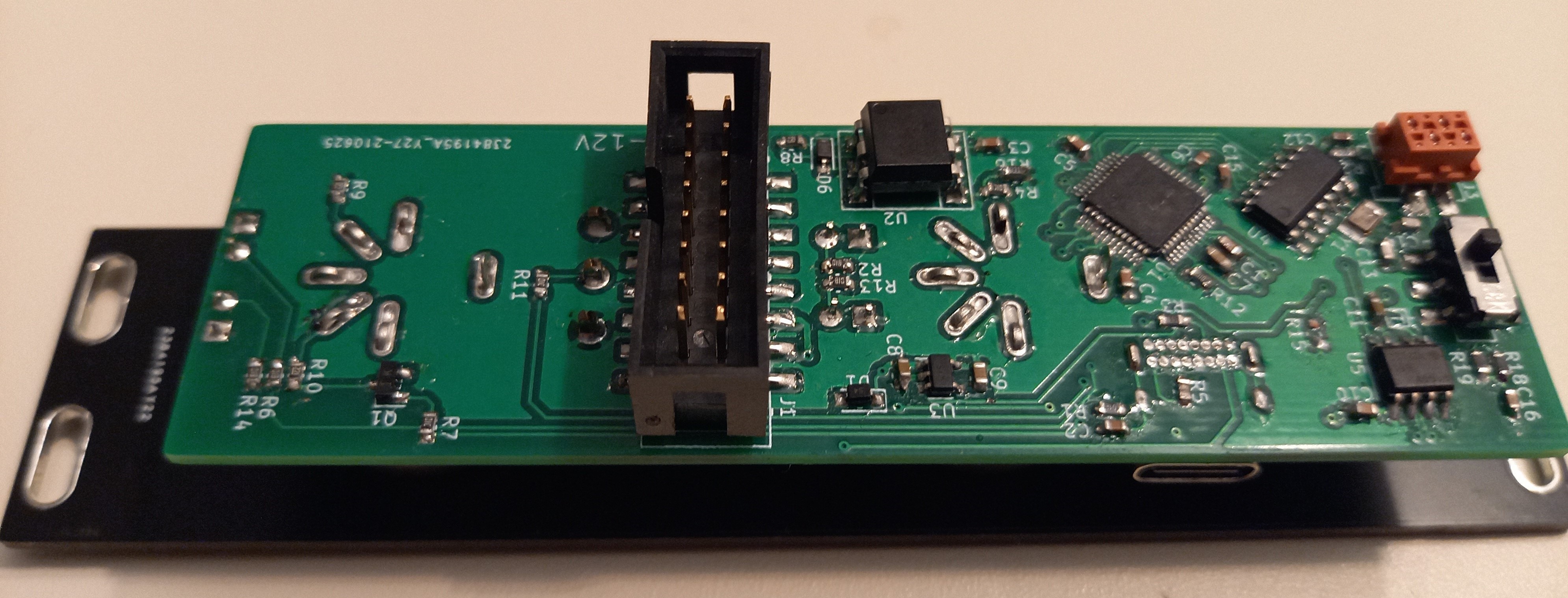
This PCB was mounted orthogonal to the front-plate, because it makes the module slimmer. The 3.5mm jacks are holding these boards together. This module has a 4-layer PCB to make the routing more compact, because deep modules won't fit in some eurorack cases.
![]()
The bottom-side contains digital circuits like the microcontroller, and CAN circuits.
-
Module #3 - Multiplexer
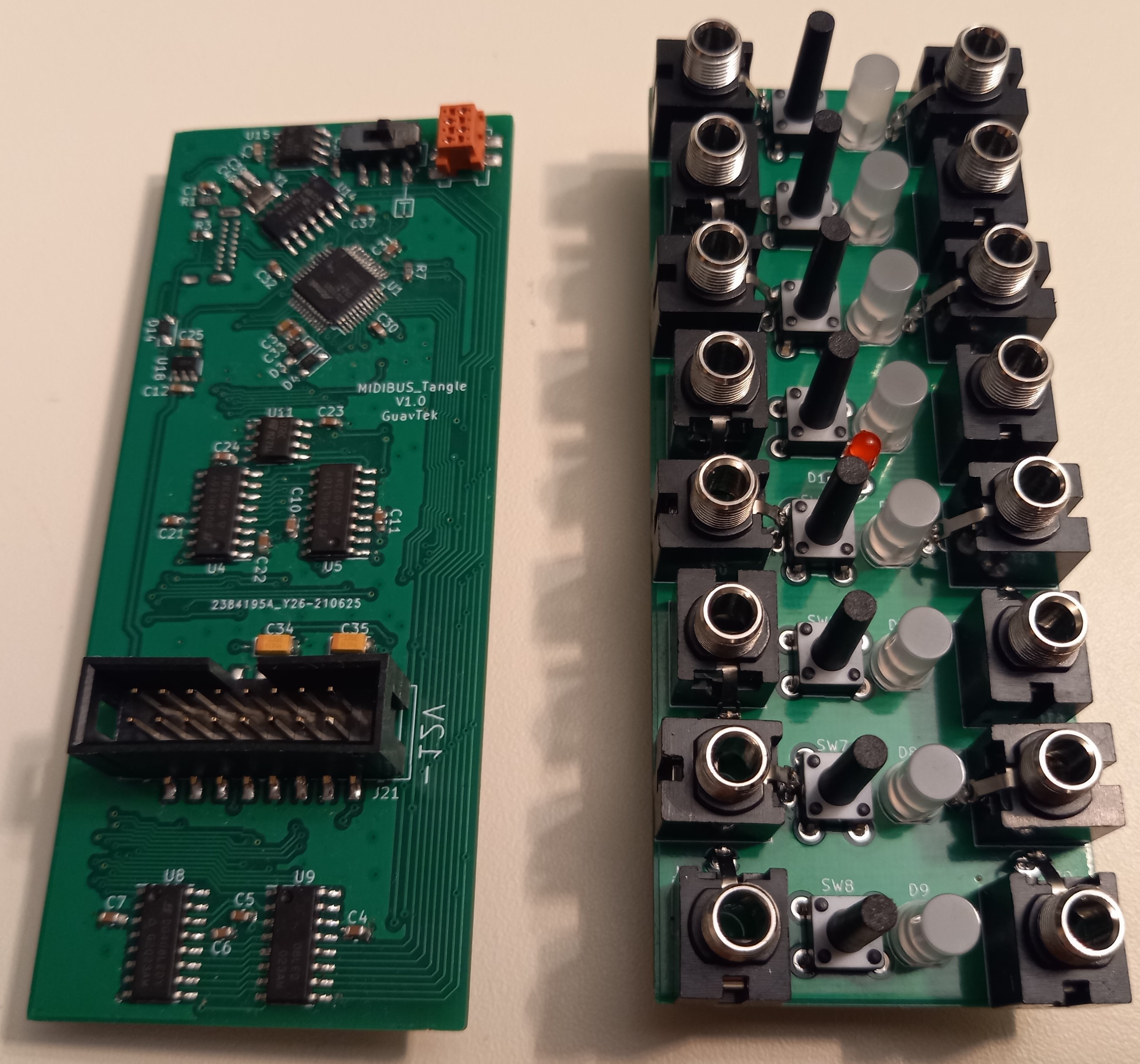
10/15/2021 at 15:50 • 0 commentsThe multiplexer module (or tangle module) provides MIDI controlled routing. It can change patches with a program change message. The thought is that it can be used to recall patches during a performance, or between songs. The schematics and PCBs can (eventually) be viewed on CADLab.
This circuit consists of eight analog multiplexers, where each output is buffered and can select one of the inputs. This means that several outputs can select the same input, but an output can not give a mix of two inputs. There is a bi-color LED on each output indicating their voltage.
The buttons are connected in a 2x4 matrix to save pins on the MCU. Actually, the red LED is connected to the data pin of the programming interface because absolutely all the pins were used.
![]()
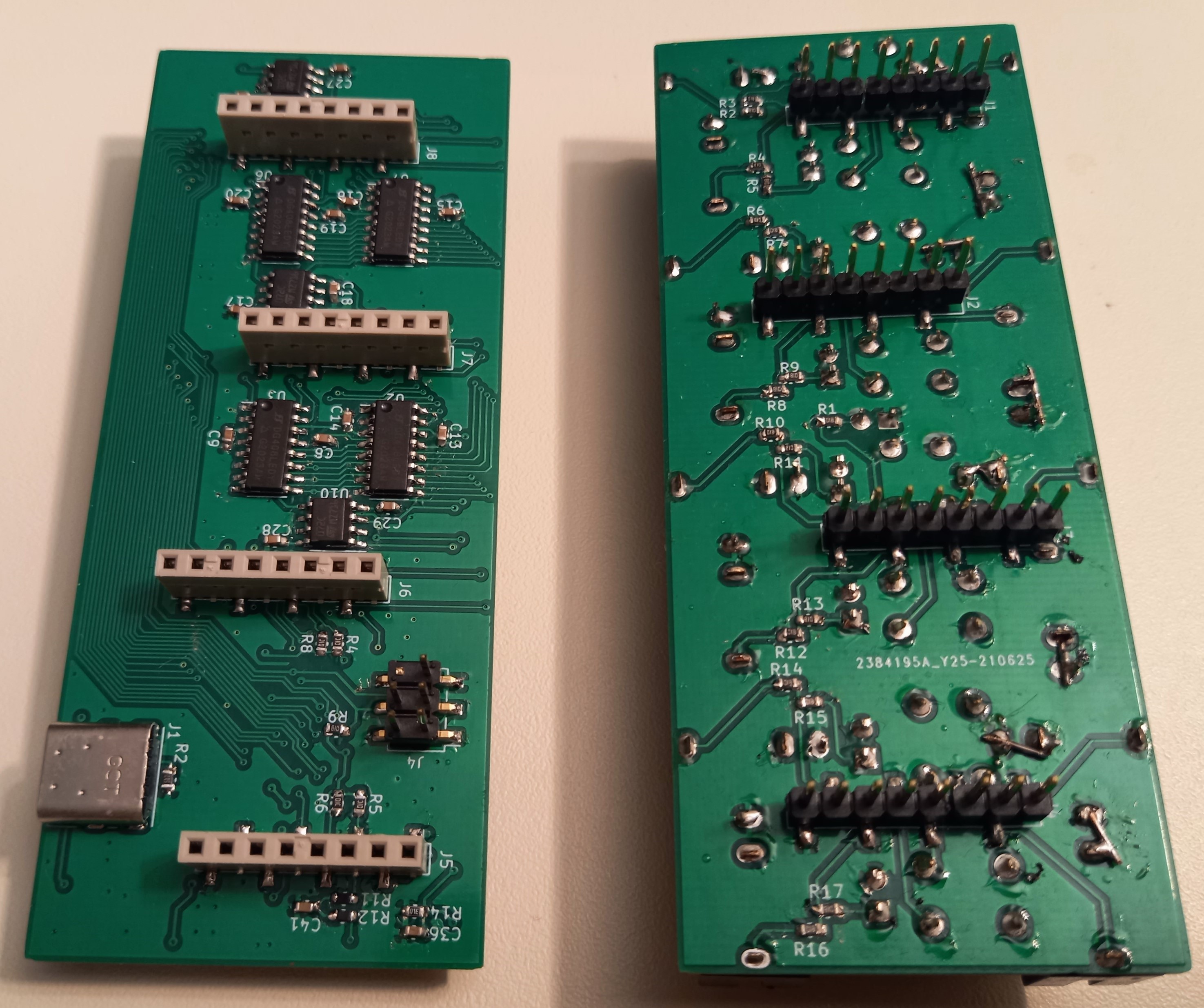
Laying out this PCB (left) has been my biggest routing challenge to date. I all the parallel traces pretty satisfying.
![]()
I had to do some botching (right PCB) because floating inputs would pick up signals from other inputs.
-
Module #2 - Control Voltage
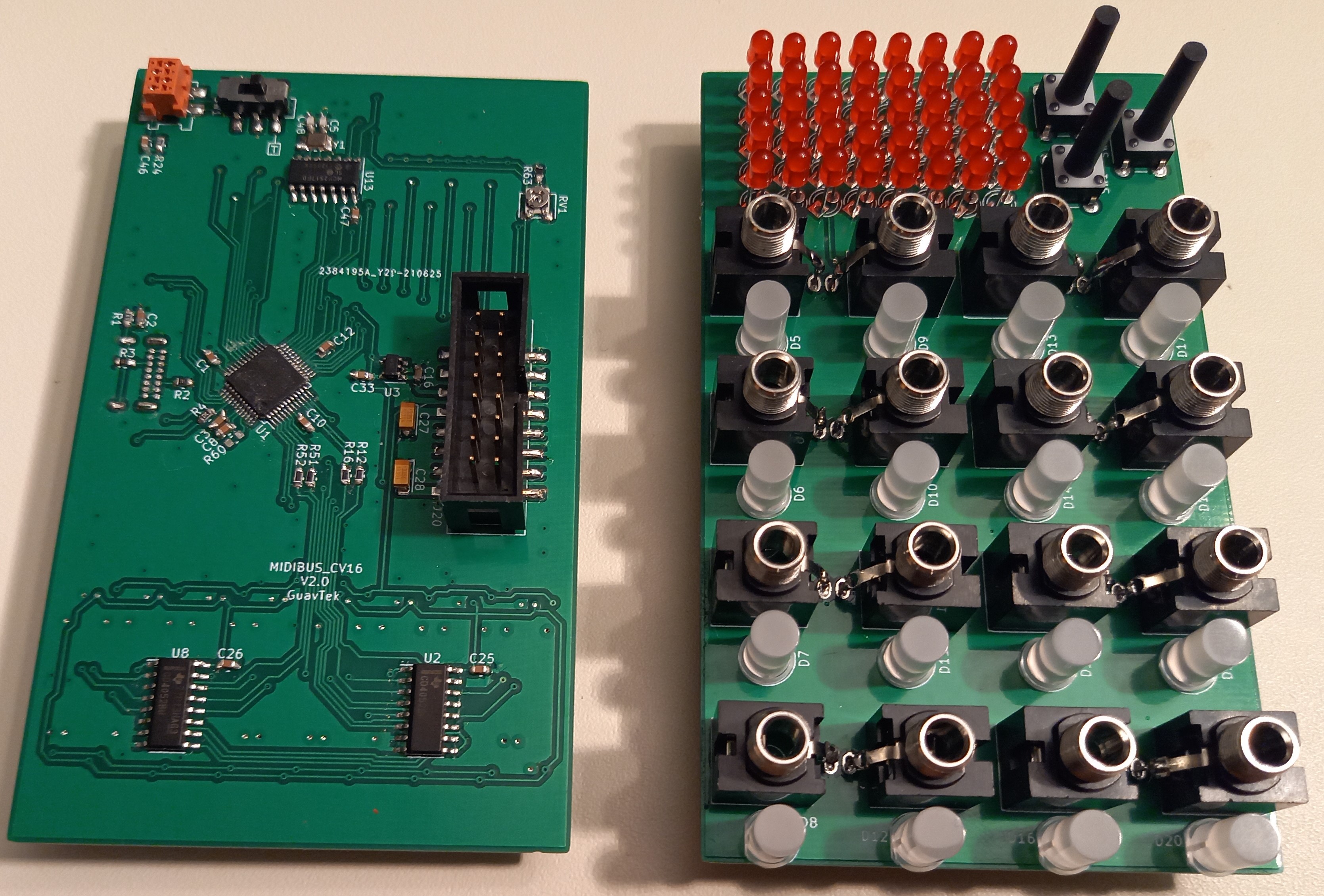
10/15/2021 at 15:48 • 0 commentsThis module is a general control voltage module. It can generate DC voltages, low frequency signals and envelopes. It is intended to be configurable so it can be used in many different setups. It should also be possible to save configurations to EEPROM to recall them later, and quickly change between them. The schematics and PCBs can be viewed on CADLab.
The analog voltages are generated by filtering PWM. This leads to a trade-off between speed, ripple, and resolution. The speed of the outputs doesn't need to be higher than 20Hz. A resolution around 16-bits should be plenty for a prototype. And the ripple should be very low, we don't want it to sound shaky. This design is using four PWM outputs which are multiplexed, using a sample-and-hold method. The capacitors used in the sampling are also part of the low-pass filters, to reduce the part count. The voltage is then scaled, offset, and buffered by an opamp. Bi-color LEDs are connected to these outputs to indicate their current voltage.
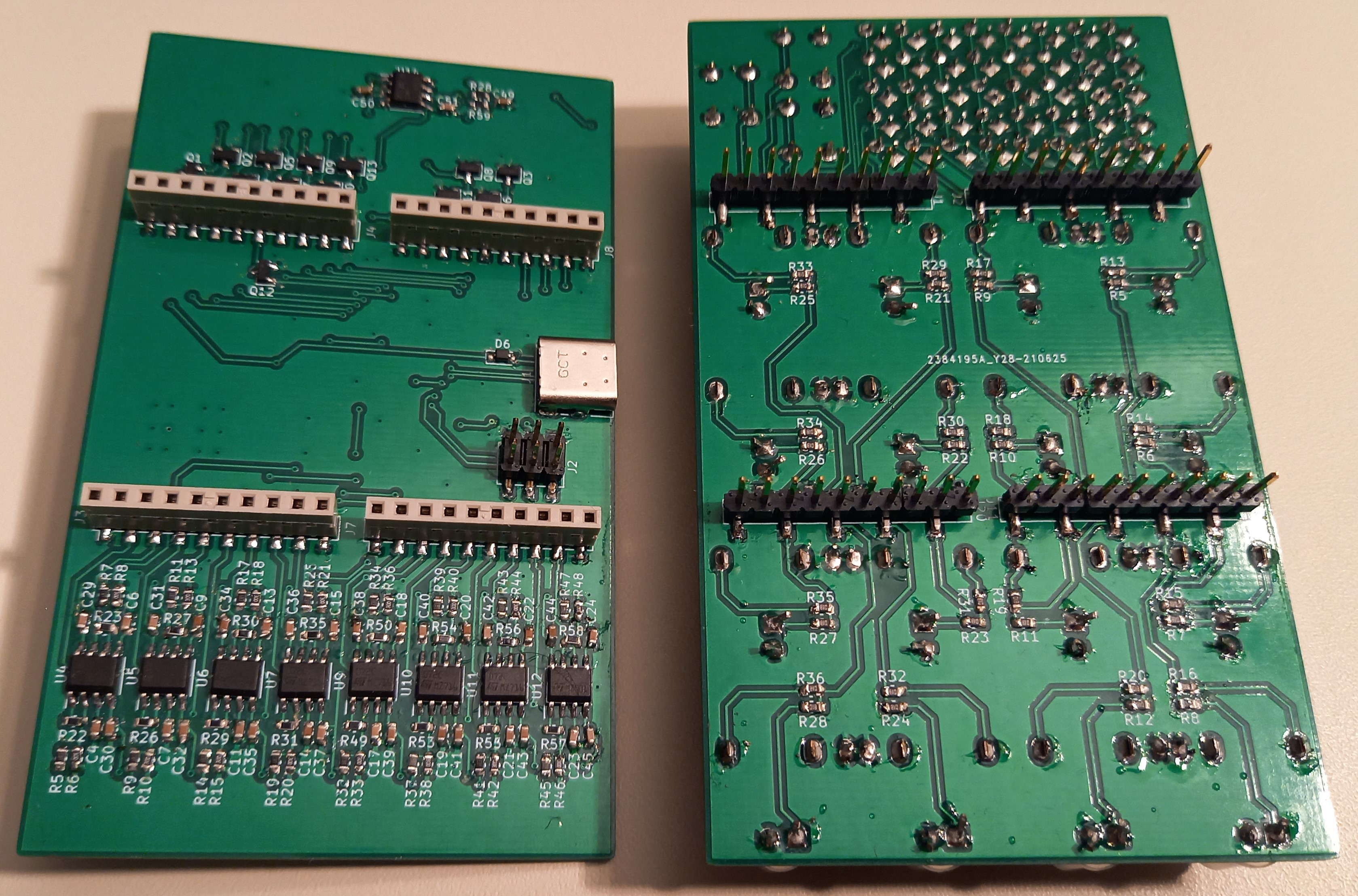
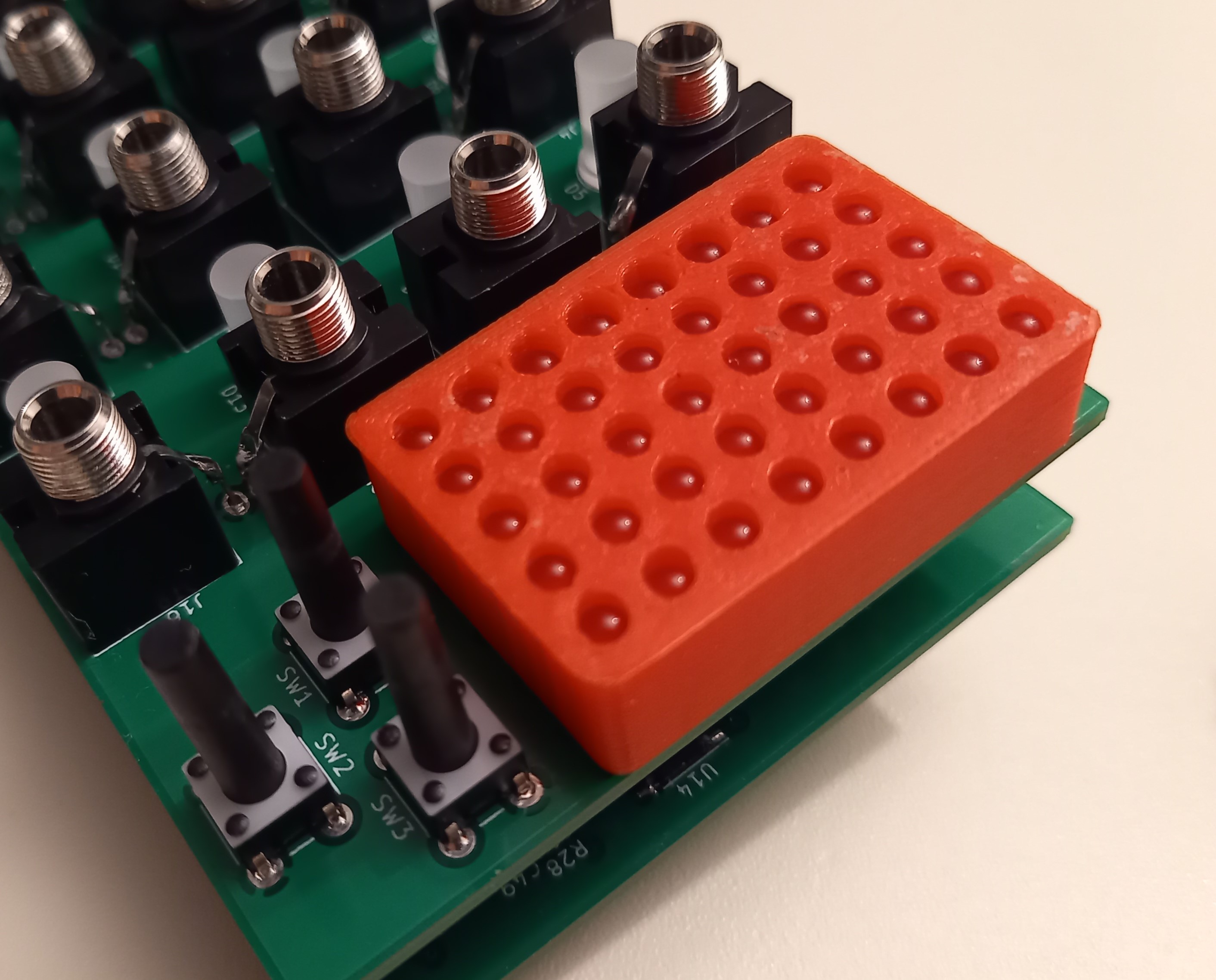
A general module like this will need a good user interface so it isn't frustrating to configure. A display module would be very versatile, but I've had some bad experience with them. So I decided to use an 8x5 LED-matrix instead. This means the info will be a bit cryptic, but it is easy to read, and a stylized look like this can be cool. This module is meant to be "set and forget" so it doesn't need immediate access to all parameters. So it has three buttons to navigate menus. It should be good enough for a prototype anyway.
![]()
![]()
The module is a sandwich of two PCBs.
![]()
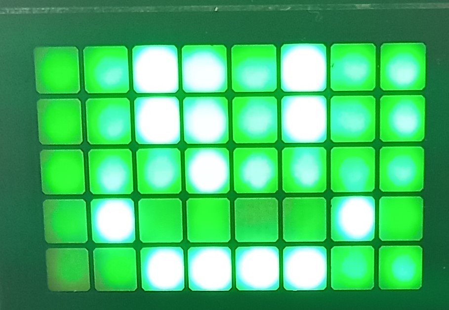
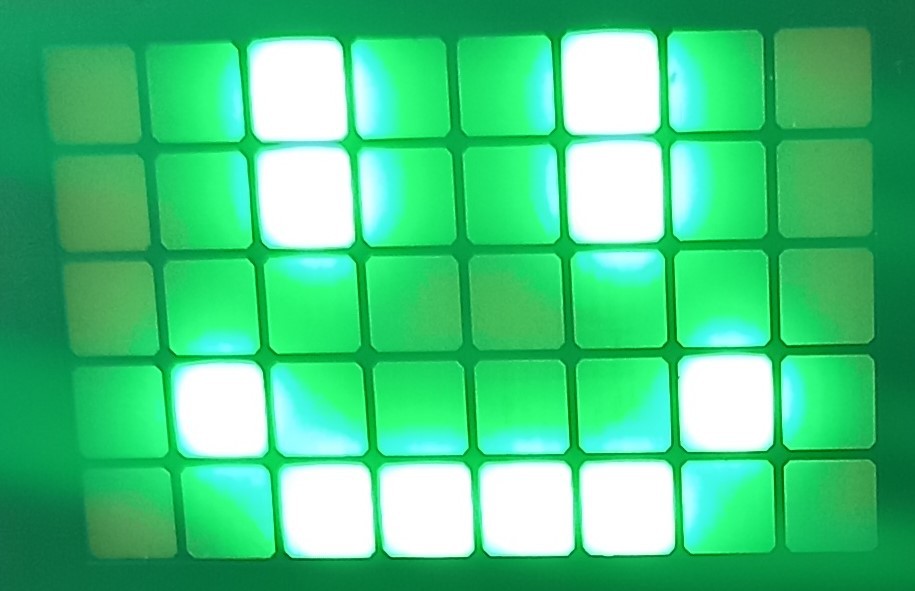
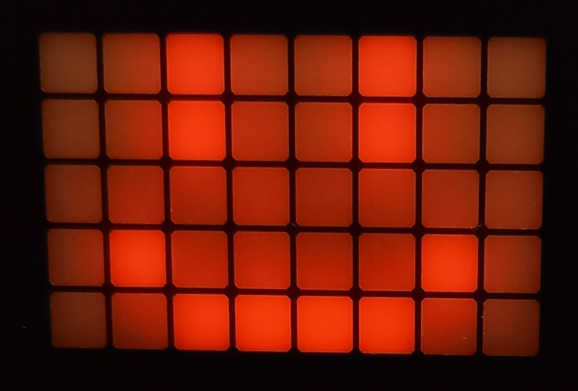
After some testing I discovered that the LED-matrix was a bit dim, but there was still a lot of bleed between the pixels. I did expect it to bleed, but I was somehow surprised by the amount. To fix the bleeding I 3D-printed a separator. As for them being dim: I should get some brighter LEDs, 50mcd was not enough.
![]()
Without the separator
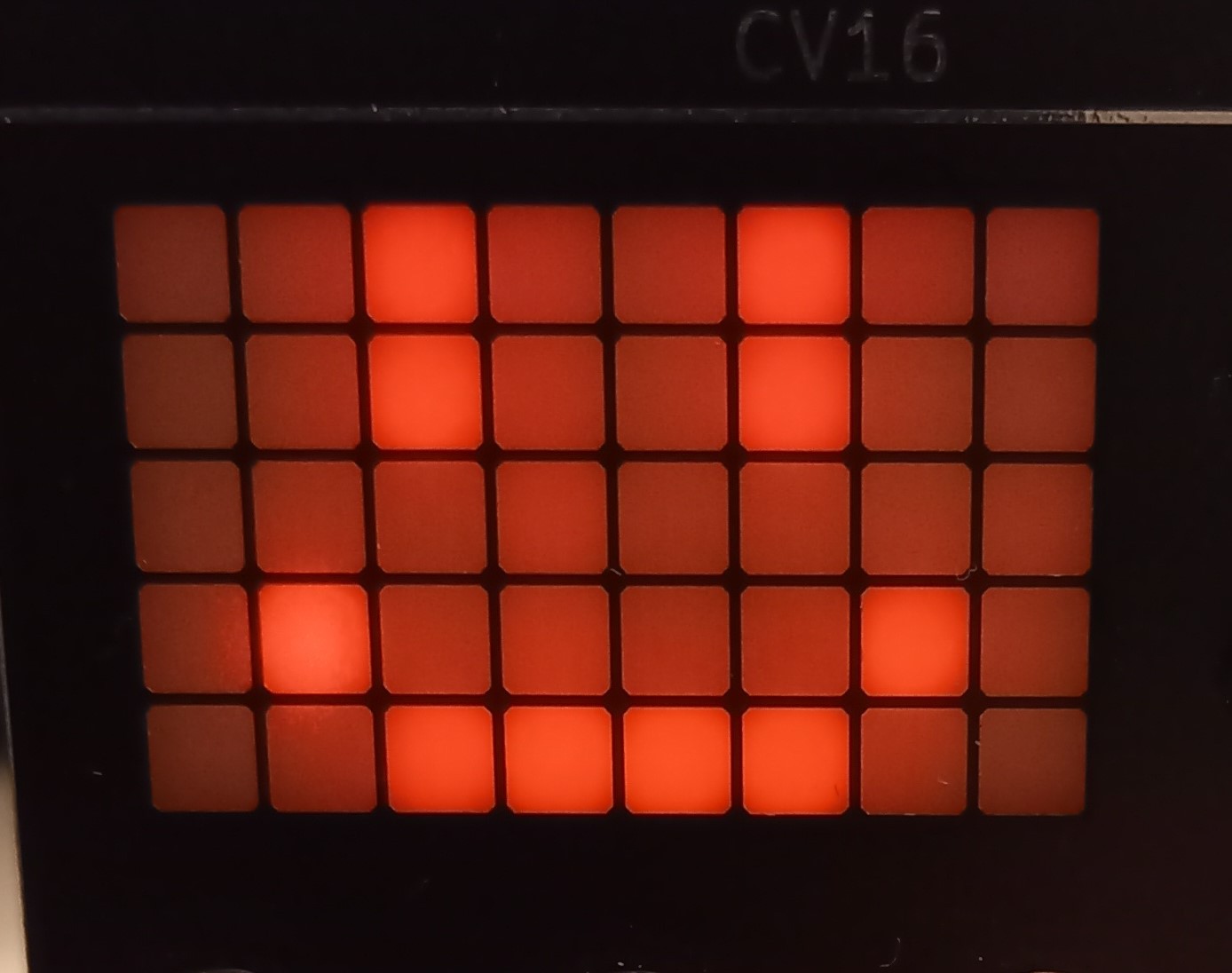
![]()
With the separator
-
Module #1 - DIN
10/15/2021 at 15:44 • 0 commentsThe DIN-5 module was the most straight forward. Most of this circuit is retained from the previous I2C version. Its purpose is to act as a gateway between the classical DIN-5 MIDI transport, and the CAN bus. The schematics and PCBs can be viewed on CADLab.
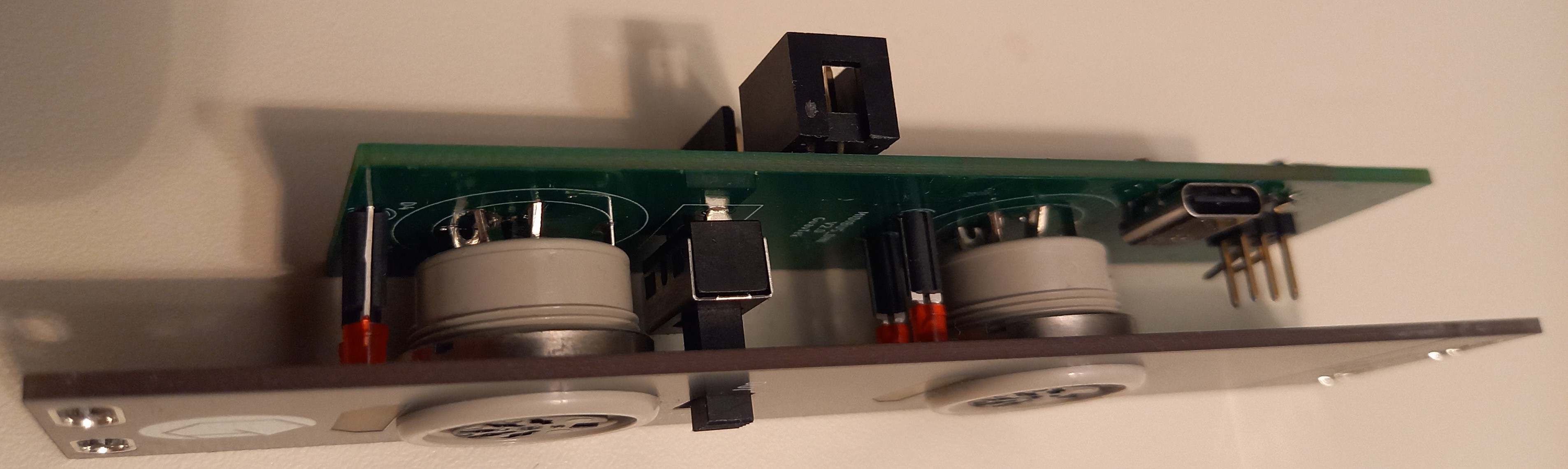
This module has one DIN input, and one DIN output. There is a switch to decide if messages from the input should be merged with the output (Thru + Out). It also has a USB-C connector to program it via a bootloader.
![]()
The assembled module looks like this.
![]()
The front-plate is held in place by the DIN connectors and can't be removed after it has been assembled. This made reaching the programming header a challenge.
The LEDs shine through the PCB. The Solder mask and copper has been removed from both sides in that area, and the FR-4 acts as a diffuser.
Modular MIDI
Using a CAN bus to distribute MIDI messages in a modular synthesizer