-
1Create a tinyML model using Edge Impulse
In this step we will build the tinyML model using Edge Impulse to analyze respiratory health of a person. I am building a tinyML model on to labels cough and healthy breath for testing purpose. However any one can easily build the model for identifying any any other respiratory illness using the same technique given that the data-set is available for that particular disease that one wants to identify.
I myself continuously working on gathering and finding the data-set for Covid-19 and pneumonia etc. so that I can update my model to work for these diseases as well.
Before you can start developing the tinyML model, you need to have an account on Edge Impulse which is free for developers. Once you have the account, login to your account, choose create a new project
![Create new project]()
Image: Create new project
and choose name to your project and then click on create new project button.
![Give name to your project]()
Image: Give name to your project
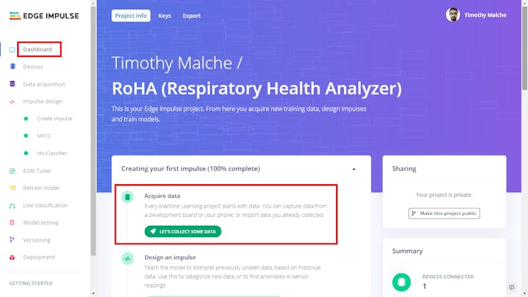
after this, the next step is gathering the data for your project. For this go to dashboard and click on lets collect some data button.
![Collect Data]()
Image: Collect Data
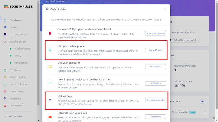
When you click the button the following screen will appear.
![Choose data option]()
Image: Choose data option
In this screen, if you already have data-set in WAV format then you can use upload data option, other wise choose use your mobile phone option to record data for the model. If you choose upload data option the following screen will appear, from here you can choose one or multiple files and specify label for those group of files and than click begin upload button to upload data.
![]()
I have used use your mobile phone option which opens the following window.
![QR code for mobile]()
Image: QR code for mobile
You need to scan this code to upload data from mobile phone. Once you scan and click on the URL, you need to go through the steps as illustrated in following figure.
![Steps to record data]()
Image: Steps to record data
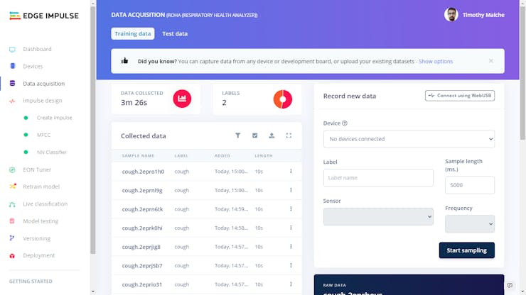
In STEP 1 once your phone is connected, click on collecting audio button. In STEP 2 click give access to microphone button. In STEP 3 specify label (cough and healthy breathing in this example), length values and click on start recording button. Then record the data as in STEP 4, the data will be automatically uploaded to Edge Impulse after recording is done. You can record data for different labels in this way. The uploaded data is visible on your project's dashboard on Edge Impulse.
![Data on Edge Impulse]()
Image: Data on Edge Impulse
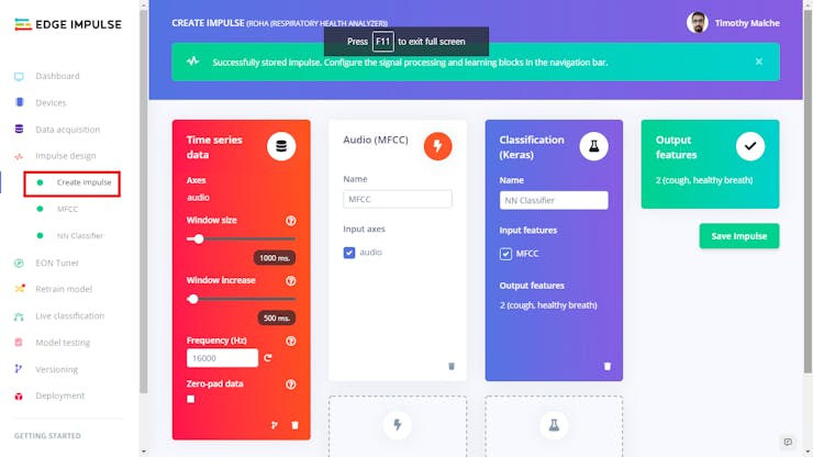
After this choose Create Impulse under Impulse Design in the left navigation and add processing and learning blocks as per following figure.
![Design impulse]()
Image: Design impulse
Then go to MFCC and verify your data. You can filter out data at this step.
![MFCC verify/filter data]()
Image: MFCC verify/filter data
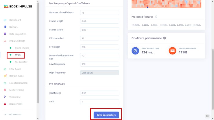
Once you done, click on save parameters option.
![MFCC: save parameters]()
Image: MFCC: save parameters
After this the following window will appear, in this window click on Generate Features button.
![Generating features]()
Image: Generating features
Then choose NN Classifier from left navigation.
![NN settings]()
Image: NN settings
You can change settings or leave it default. Then click on start training.
![Start Training]()
Image: Start Training
Your model will be trained and you will see the result.
![Training output]()
Image: Training output
![Model accuracy]()
Image: Model accuracy
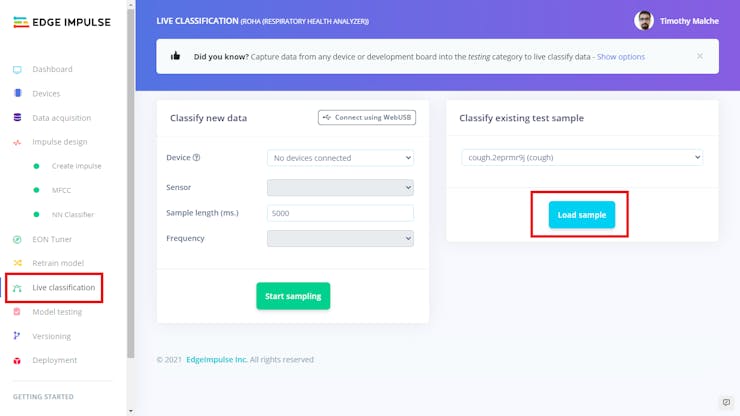
From the above figures we can see that our model is perfectly build and trained on data. You can choose Live Classification in the left navigation to test the data. You can then choose your phone to get data for live sampling by clicking start sampling button or load the existing sample test data by choosing sample data from drop down list and clicking load sample button.
![Load sample]()
Image: Load sample
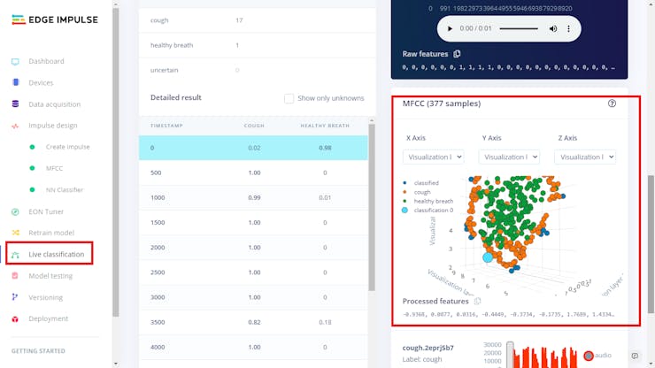
When you load the sample, the live classification will be done and you can see the model performance.
![Live classification result]()
Image: Live classification result
Live classification test your model against single sample at a time. You can choose the Model Testing option to test your model against multiple test samples from test data. For this click on the Classify all button and you will see the model performance. As you can see in following figure that my model is working perfectly.
![Model Testing]()
Image: Model Testing
Once you done the testing choose Deployment from left navigation to create the library that we will use later on to build the firmware. In the window that appear choose Arduino Library.
![Deploy as Arduino Library]()
Image: Deploy as Arduino Library
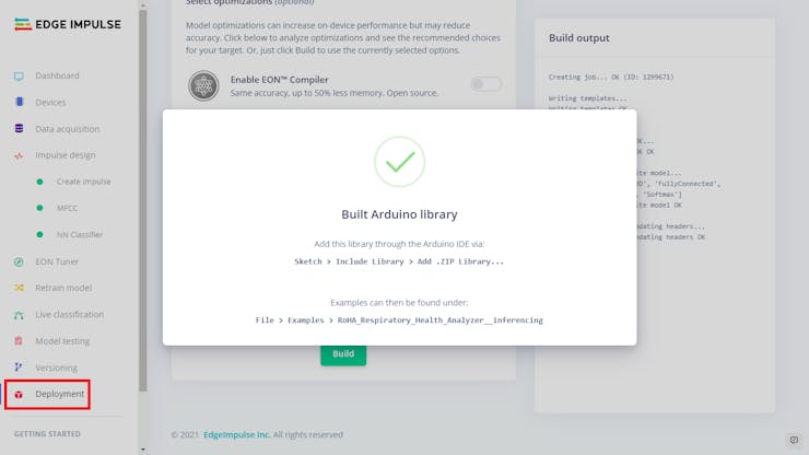
Now scroll down and click on build library button.
![Build the library]()
Image: Build the library
The Edge Impulse automatically build the library and it will be automatically downloaded as zip file.
![Arduino library as Zip file]()
Image: Arduino library as Zip file
Keep this zip file for next step.
-
2Setup environment for AWS IoT Edu Kit
Now in this step we are going to set up the environment for the AWS IoT Edu Kit.
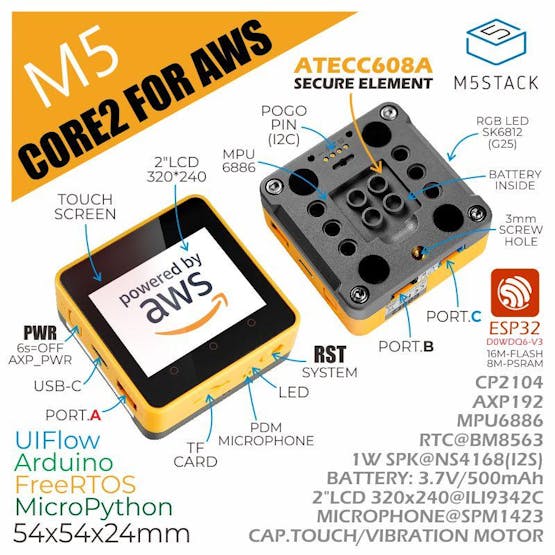
![M5Stack Core2 ESP32 IoT Development Kit for AWS IoT EduKit]()
Image: M5Stack Core2 ESP32 IoT Development Kit for AWS IoT EduKit
First download the official Arduino IDE. Now first we need to install ESP32 Boards Manager. For this open up the Arduino IDE, and navigate to
File -> Preferences -> Settings.![Arduino settings]()
Image: Arduino settings
Add the following ESP32 Boards Manager URL to Additional Boards Manager
https://m5stack.oss-cn-shenzhen.aliyuncs.com/resource/arduino/package_m5stack_index.json![Additional Boards Manager URL]()
Image: Additional Boards Manager URL
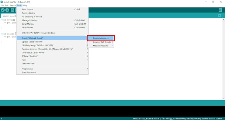
Thengo toTools->Board->Boards Manager![Boards Manager]()
Image: Boards Manager
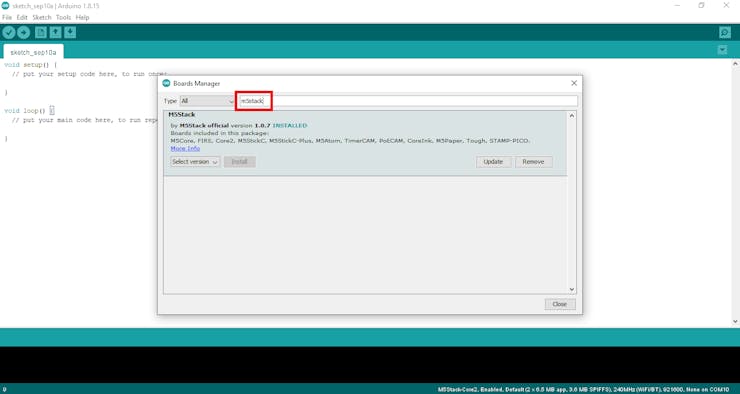
And search
m5stackin the Boards Manager window, and click Install.![Install M5Stack Board]()
Image: Install M5Stack Board
Once board is installed, go to
Tools -> Board: -> M5Stack Arduino -> M5Stack-Core2as your board as shown in the following figure.![Select board]()
Image: Select board
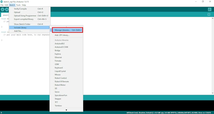
Now we also need M5Stack Library to work with. Go to
Sketch -> Include Library -> Manage Libraries...![Manage Library]()
Image: Manage Library
Then search
M5Core2, find it and click Install.![Install M5Core2 Library]()
Image: Install M5Core2 Library
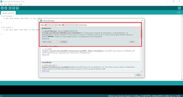
You will also need ArduinoJson library that we will use later on.
![Installing ArduinoJson Library]()
Image: Installing ArduinoJson Library
Now we will add the zip library for our model that we have developed using Edge Impulse. For this go to
Sketch -> Include Library -> Add ZIP Library...![Add ZIP Library]()
Image: Add ZIP Library
andselect the ZIP library.![Select ZIP library]()
Image: Select ZIP library
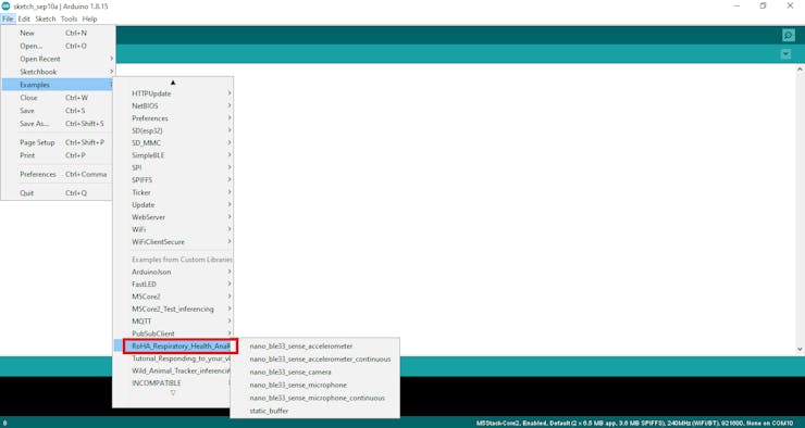
Once the library is installed you can see it in Arduino IDE.
![RoHA Library is installed]()
Image: RoHA Library is installed
-
3Configure AWS IoT core
For this step first you need AWS account and need to sign in to the AWS Console your account.
![Sign in to Console]()
Image: Sign in to Console
If you don't have account then click on create new account otherwise sign in.
![Sign in to AWS Console or create account]()
Image: Sign in to AWS Console or create account
After you sign in you will see AWS Management console. We will use the search box to access different services.
![AWS Management console (main page)]()
Image: AWS Management console (main page)
In the search box type AWS IoT and select IoT Core.
![Select ASW IoT Core]()
Image: Select ASW IoT Core
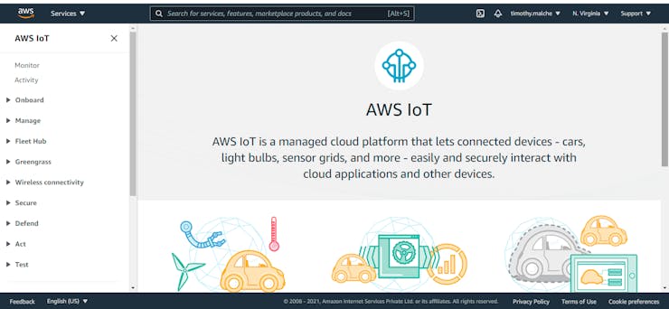
You will see the following page.
![AWS IoT main page]()
Image: AWS IoT main page
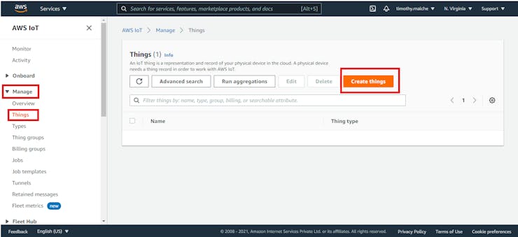
Now go to Manage in on the left navigation and choose Things and in the window on the right click Create things Button.
![Creating Things]()
Image: Creating Things
In the next window choose Create single thing option and click on Next button.
![Create a single thing]()
Image: Create a single thing
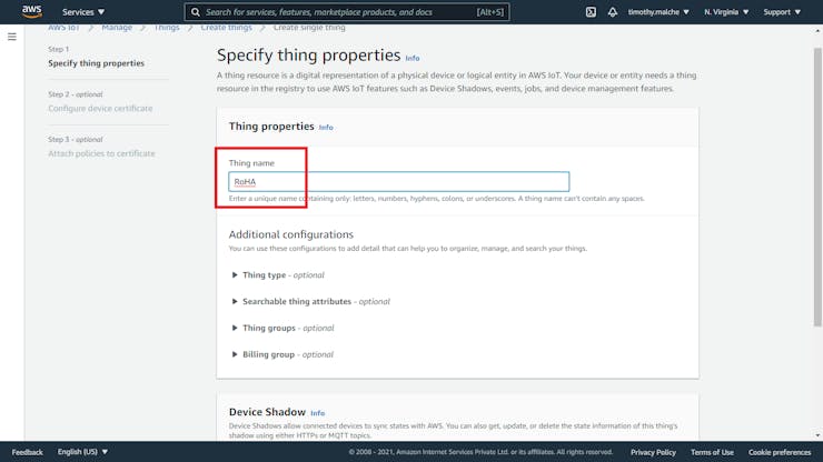
Next, specify your Thing name.
![Specify Thing name]()
Image: Specify Thing name
Leave other settings as it is and click on Next button.
![Create Thing]()
Image: Create Thing
In the next window choose option Auto-generate a new certificate and click next.
![Auto-Generate certificate]()
Image: Auto-Generate certificate
In the next window click Create policy. It will open in new window. You can also create and attach policy later on but its good to create it here.
![Create policy]()
Image: Create policy
In the window that appear in new tab/window of your web browser, specify a unique name to the policy and Action as * and Resource ARN as * as well and under Effect select Allow. After this click on Create button.
![Policy Settings]()
Image: Policy Settings
![Policy created]()
Image: Policy created
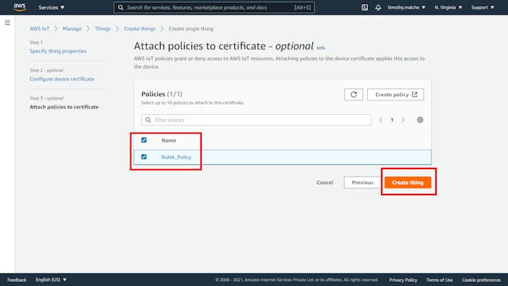
Now come back to previous window from browser tab there you will see the name of policy you have created. Now select the policy to attach it with your Thing and then click on Create thing button.
![Attach policy and create thing]()
Image: Attach policy and create thing
When thing is created you will be prompt to download certificate and keys. Download them and keep at safe place.
![Download certificate and keys]()
Image: Download certificate and keys
After you have downloaded, click Done button.
![Create Thing]()
Image: Create Thing
You will see your thing created with the policy attached to it.
![Thing created]()
Image: Thing created
-
4Configure IAM
AWS Identity and Access Management (IAM) enables you to manage access to AWS services and resources securely. Using IAM, you can create and manage AWS users and groups, and use permissions to allow and deny their access to AWS resources. We need this step as we will be using DynamoDB service in PHP application. Therefore to access DynamoDB programmatically or through the AWS Command Line Interface (AWS CLI), we must have an AWS access key. Access keys consist of an access key ID and secret access key, which are used to sign programmatic requests that you make to AWS. For this we first need to create IAM user and then create the access key. To access IAM service type IAM in the search bar of AWS console and choose IAM.
![Access IAM service]()
Image: Access IAM service
In the dashboard click on users on the left navigation and then click Add user button on the right side.
![Adding User]()
Image: Adding User
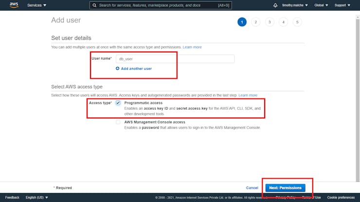
Specify the unique user name as db_user and and select Programmatic access and click on next button.
![DB user settings]()
Image: DB user settings
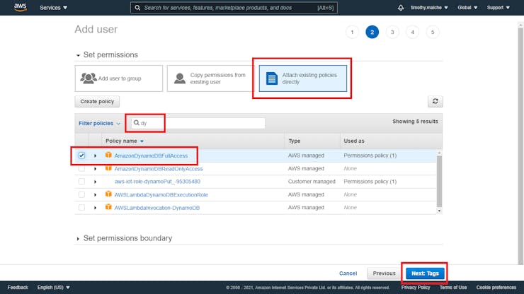
In the next window click on tab Attach existing policies directly and in filter policies type 'dy' and select AmazonDynamoDBFullAccess. After this click on next button.
![Attach policy to user]()
Image: Attach policy to user
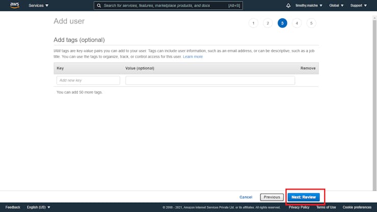
The Add Tag window will appear. This is optional step so just go to bottom of page and click next.
![Add tag (no setting required)]()
Image: Add tag (no setting required)
Next, review the settings and click Create user button at bottom.
![Review settings]()
Image: Review settings
The user will be created. You can now get the Access key ID and secret key from the page and even you can download the same in CSV file for later use. This will be required in our PHP program.
![IAM User credentials]()
Image: IAM User credentials
-
5Configure DynamoDB service
In this step we are going to configure DynamoDB database service where our data will be stored permanently. To access DynamoDB service, go to AWS Console and in search box type DynamoDB then from the list select DynamoDB.
![Search DynamoDB service]()
Image: Search DynamoDB service
The dashboard of DynamoDB will open.
![DynamoDB Dashboard]()
Image: DynamoDB Dashboard
In the dashboard click on Create table button. We'll create a DynamoDB table to record data from sensor node.
- In Table name, enter the table name:
wx_data. - In Primary key, in Partition key, enter
sample_time, and in the option list next to the field, choose Number. Check Add sort key. - In the field that appears below Add sort key, enter
device_id, and in the option list next to the field, choose Number. - At the bottom of the page, choose Create.
We'll define
device_datalater, when we configure the DynamoDB rule action.device_datafield will be used to store the actual data from sensor node.![Table details]()
Image: Table details
- In Table name, enter the table name:
-
6Create AWS IoT rule for DynamoDB
Now we will create an AWS IoT rule to send data to the DynamoDB table. This rule will then be used to store the data from sensor node to DynamoDB via AWS IoT core.
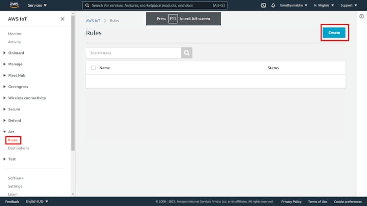
- Open the Rules hub of the AWS IoT console.
- To start creating your new rule in Rules, choose Create.
![Creating rule]()
Image: Creating rule
In Name, enter the rule's name,
wx_data_ddb. In Using SQL version, select<b>2016-03-23</b>.![Specify rule name]()
Image: Specify rule name
In the Rule query statement edit box, enter the statement:
SELECT status FROM 'device/+/data'
and then click Add action
![rule query statement]()
Image: rule query statement
In Select an action, choose Insert a message into a DynamoDB table.
![Select an action]()
Image: Select an action
and then click Configure action.
![Select action]()
Image: Select action
Now the configure action window will open.
- In Table name, choose the name of the DynamoDB table you created in a previous step:
wx_data. - In Partition key value. enter
${timestamp()}. - In Sort key value, enter
${cast(topic(2) AS DECIMAL)}. - In Write message data to this column, enter
<b>device_data</b>. This will create thedevice_datacolumn in the DynamoDB table to store data from sensor node. - Leave Operation blank.
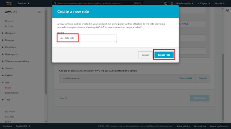
- In Choose or create a role to grant AWS IoT access to perform this action, choose Create Role.
![]()
- In Create a new role, enter
<b>wx_ddb_role</b>, and choose Create role.At the bottom of Configure action, choose Add action. - To create the rule, at the bottom of Create a rule, choose Create rule.
![Create role]()
Image: Create role
Your rule will be created.
-
7Test the AWS IoT rule and DynamoDB table
Now we will test if the rule is working. To test the new rule, we'll use the MQTT client to publish and subscribe to the MQTT messages used in this test. Go to AWS IoT Core, in the left navigation go to
Test -> MQTT test ClientIn the MQTT client, choose Subscribe to a topic. For Topic filter, enter the topic of the input topic filter,
<b>device/+/data</b>. Choose Subscribe.![MQTT Subscribe]()
Image: MQTT Subscribe
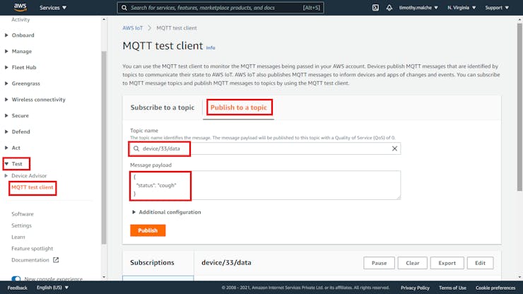
Now, publish a message to the input topic with a specific device ID, device/33/data. You can't publish to MQTT topics that contain wildcard characters.
In the MQTT client, choose Publish to a topic. For Topic name, enter the input topic name, device/22/data. For Message payload, enter the following sample data.
{"status" : "cough"}![MQTT Publish]()
Image: MQTT Publish
When you click publish button, you will see the data published and when you open the DynamoDB table you will see the same data being stored there.
To view data published go to DynamoDB dashboard, click on Tables in the left navigation and in the window on right click on your table name.
![Select table to view data]()
Image: Select table to view data
In the next window, click on view items.
![Click to view table data]()
Image: Click to view table data
In the open window, scroll down to view data there you can see the data.
![View DynamoDB data]()
Image: View DynamoDB data
In the next step we will build the firmware.
-
8Build the firmware
Open the Arduino IDE and create a new sketch with name
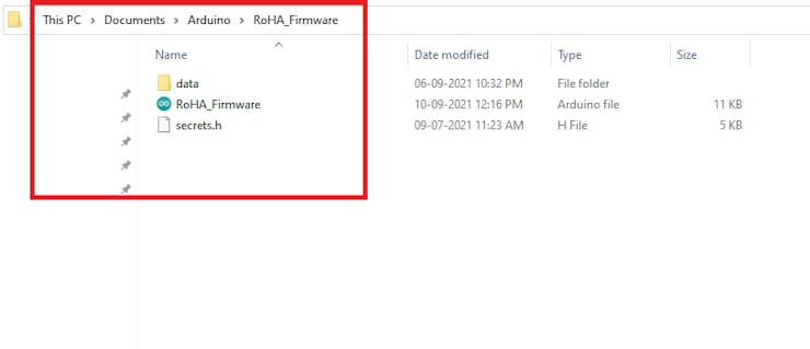
RoHA_Firmware.ino. Create a header file with namesecrets.hin the same folder and one subfolder named data.secrets.hheader file stores device certificate and keys and data folder will contain an image that we will load on sensor node when it boots up. Your directory structure would look like following.![Firmware directory structure]()
Image: Firmware directory structure
Following is the structure of
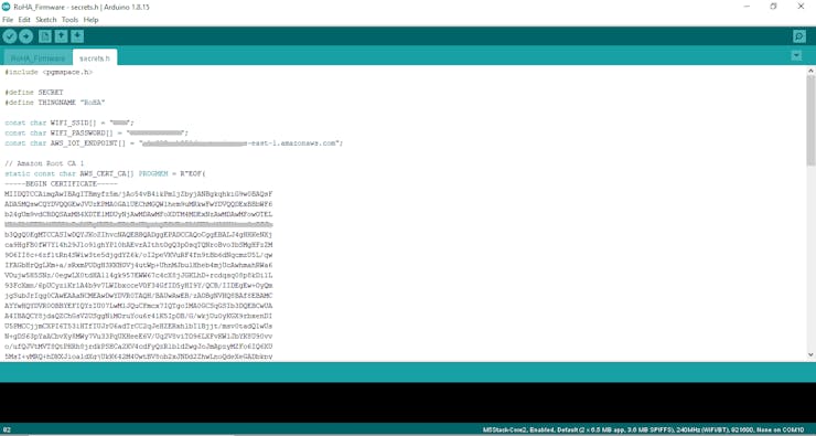
secrets.hfile#include <pgmspace.h> #define SECRET #define THINGNAME "RoHA" const char WIFI_SSID[] = "WIFI SSID"; const char WIFI_PASSWORD[] = "WIFI PASSWORD"; const char AWS_IOT_ENDPOINT[] = "YOUR AWS END POINT HERE"; // Amazon Root CA 1 static const char AWS_CERT_CA[] PROGMEM = R"EOF( -----BEGIN CERTIFICATE----- -----END CERTIFICATE----- )EOF"; // Device Certificate static const char AWS_CERT_CRT[] PROGMEM = R"KEY( -----BEGIN CERTIFICATE----- -----END CERTIFICATE----- )KEY";In the file you need to paste the
Amazon Root CA 1,Device Certificate, andDevice Private Keywhich we have downloaded in the Configure AWS IoT core step of this project documentation. You also need to specify yourWiFi SSID,PASSWORD, andAWS Endpoint. It will look something like following.![secret.h file]()
Image: secret.h file
You can get the values to
Amazon Root CA 1,Device Certificate, andDevice Private Keyfrom the files downloaded in step Configure AWS IoT core. See the following figure.![The files the stores the credentials of AWS IoT Core for secrets.h file]()
The files the stores the credentials of AWS IoT Core for secrets.h file
Also, you can find the AWS IoT endpoint from AWS IoT Core console. Scroll down the IoT Core page to find the settings on the left navigation.
![Settings of AWS IoT Core]()
Image: Settings of AWS IoT Core
Click on settings, the following page will open. Copy endpoint name from there.
![AWS IoT Endpoint name]()
Image: AWS IoT Endpoint name
Now you can use the firmware code attached with this documentation in
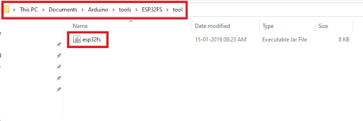
RoHA_Firmware.inofile. Before uploading the firmware we are first going to store the image to AWS IoT EduKit. This image will be used as startup image that will appear on sensor node screen when the firmware loads. To upload image we need a Arduino ESP32 filesystem uploader plugin for Arduino. Download the ESP32FS-1.0.zip file and extract it to../Arduino/toolsfolder. The directory structure should look like following.![Data uploader plugin path]()
Image: Data uploader plugin path
If there is no tools folder under Arduino folder then create it.
Restart the Arduino IDE and you should be able to see the option to upload data as shown below.
![ESP Sketch data upload]()
Image: ESP Sketch data upload
now store the image in the data folder within the main firmware folder. The directory structure will be as follows.
![Firmware Data Folder]()
Image: Firmware Data Folder
The resolution of image should be 320x240.
Now first upload the data using ESP32 data upload tool in Arduino and then compile and upload the firmware also. Make sure that you have included the correct model library and other required library.
![RoHA Firmware Code]()
Image: RoHA Firmware Code
We will now understand the few important lines in firmware code. In the code the following variable is used to store data from microphone.
static signed short sampleBuffer[2048];The topic to which sensor node can publish and subscribe are following.
// The MQTT topics that this device should publish/subscribe
#define AWS_IOT_PUBLISH_TOPIC   "device/33/data"
#define AWS_IOT_SUBSCRIBE_TOPIC "device/33/data"
The
connectAWS()function connects to AWS IoT core. The function uses AWS IoT devices credentials and endpoint fromsecrets.hheader file.void connectAWS(){ WiFi.mode(WIFI_STA); WiFi.begin(WIFI_SSID, WIFI_PASSWORD); Serial.println("Connecting to Wi-Fi"); while (WiFi.status() != WL_CONNECTED){ delay(500); Serial.print("."); } // Configure WiFiClientSecure to use the AWS IoT device credentials net.setCACert(AWS_CERT_CA); net.setCertificate(AWS_CERT_CRT); net.setPrivateKey(AWS_CERT_PRIVATE); // Connect to the MQTT broker on the AWS endpoint we defined earlier client.begin(AWS_IOT_ENDPOINT, 8883, net); // Create a message handler client.onMessage(messageHandler); Serial.print("Connecting to AWS IOT"); while (!client.connect(THINGNAME)) { Serial.print("."); delay(100); } if(!client.connected()){ Serial.println("AWS IoT Timeout!"); return; } // Subscribe to a topic client.subscribe(AWS_IOT_SUBSCRIBE_TOPIC); Serial.println("AWS IoT Connected!"); }The sensor node publishes the topic to AWS IoT Core.
void publishMessage(){
  StaticJsonDocument<200> doc;
  doc["status"] = payload;

  char jsonBuffer[512];
  serializeJson(doc, jsonBuffer); // print to client

  client.publish(AWS_IOT_PUBLISH_TOPIC, jsonBuffer);
}
In the
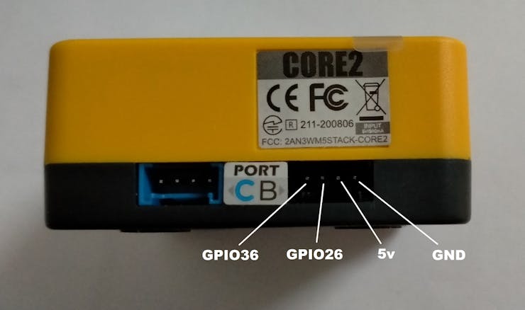
setup()function the PIR sensor is configured on pin 36 on PORT B.pinMode(36, INPUT);
![Pins on PORT-B]()
Image: Pins on PORT-B
The following code in
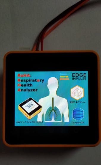
setup()display the startup image on device LCD when firmware is loaded.M5.Lcd.drawPngFile(SPIFFS, "/RoHA_Poster.png", 0, 0);The main
loopdisplay the main screen of firmware and PIR sensor data and waits for users input to record the vocal data. When the user press the left button on AWS IoT Edu Kit, the voice data recording starts and after recording is done the inference is run and output is displayed on screen. Afterwards the data is published to AWS IoT core and the main screen is again displayed to user.void loop() { M5.update(); display_title(); //Display main screen display_pir(); //Display person contact alert //Enables touch on LCD TouchPoint_t pos= M5.Touch.getPressPoint(); //Detects left button click position if(pos.y > 240) if(pos.x < 109) { //when left button is pressed if(M5.Touch.ispressed() == true){ //Recording starts and then inference is run record_and_inference(); delay(2000); //send the inference data to AWS IoT Core send_data(); delay(2000); } } }In the
record_and_inference()function the following code displays the inferencing result on LCD of the device.record_and_inference(){ ... //Printing inferencing result on M5Stack LCD M5.Lcd.setTextColor(BLACK); M5.Lcd.setCursor(10, 126); M5.Lcd.printf("%s: %.5f\n", result.classification[0].label, result.classification[0].value); M5.Lcd.setTextColor(BLACK); M5.Lcd.setCursor(10, 146); M5.Lcd.printf("%s: %.5f\n", result.classification[1].label, result.classification[1].value); //checking which label has closest value if(result.classification[ix].value > 0.50000){ //storing the label text in payload strcpy(payload, result.classification[ix].label); //check what is the status and set text and background color accordingly if (strcmp(result.classification[ix].label, "cough")==0){ M5.Lcd.setTextColor(WHITE, RED); }else{ M5.Lcd.setTextColor(WHITE, BLUE); } M5.Lcd.setCursor(10, 166); M5.Lcd.printf("STATUS: %s", result.classification[ix].label); } ... }The following function is invoked within
pdm_data_ready_inference_callback()used to read data from microphone.i2s_read(Speak_I2S_NUMBER, (char *)(sampleBuffer), DATA_SIZE, &bytesRead, (100 / portTICK_RATE_MS));The full firmware source code is attached with this document. Read instruction specified with the attached file before you upload it.
![Start Screen]()
Image: Start Screen
![Main screen (social distancing maintained)]()
Image: Main screen (social distancing maintained)
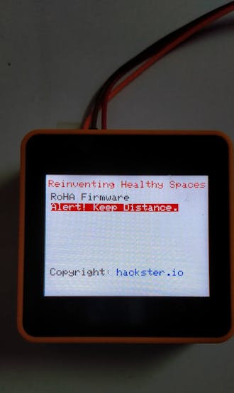
![Main Screen (Alert - person detected)]()
Image: Main Screen (Alert - person detected)
As you can see in the above figure, that an alert message is displayed whenever a proper distancing is not maintained. The
display_pir()function displays the message./* This function detects human presense and display PIR data on LCD as well as serial monitor*/ void display_pir(){ if(digitalRead(36)==1){ M5.Lcd.setTextColor(WHITE,RED); M5.Lcd.setCursor(10, 56); /* Enable haptic feedback */ M5.Axp.SetLDOEnable(3,true); delay(100); /* Disable haptic feedback */ M5.Axp.SetLDOEnable(3,false); //Display Alert on LCD M5.Lcd.print("Alert! Keep Distance."); //Debuging message on serial terminal Serial.println("PIR Status: Sensing"); Serial.println(" value: 1"); } else{ M5.Lcd.setTextColor(BLACK,WHITE); M5.Lcd.setCursor(10, 56); M5.Lcd.print("You are doing good. "); //Debuging message on serial terminal Serial.println("PIR Status: Not Sensed"); Serial.println(" value: 0"); } delay(500); }Whenever the alert is displayed, the sensor node also gives the haptic feedback. The following lines in the
display_pir()function enables the haptic feedback./* Enable haptic feedback */ M5.Axp.SetLDOEnable(3,true); delay(100); /* Disable haptic feedback */ M5.Axp.SetLDOEnable(3,false);The following images show the result of inferencing.
![Inferencing result (healthy breath)]()
Image: Inferencing result (healthy breath)
![Inferencing result (cough)]()
Image: Inferencing result (cough)
The sensor node activity can be tracked on AWS IoT Core using the Monitor option in the left navigation.
![IoT Core 'Monitoring' tool]()
Image: IoT Core 'Monitoring' tool
The uploaded data can also be viewed in DynamoDB.
![DynamoDB Table values]()
Image: DynamoDB Table values
-
9Install the Web Server
Now the next step is to install a web server. Web Server for this project can be used in two ways
- Webserver on local computer
- Webserver on hosting space on Internet
If you buy a hosting space, you do not need to install the web server. You just need to upload the code to the webserver provided with this project. If you are planning to install the webserver on local computer then I prefer XAMPP web server.
Download the XAMPP server on your local computer and install it. The steps are very simple. You can follow this guide.
-
10Get AWS SDK for PHP & build Web App
Navigate to htdocs folder in the XAMPP webservers root directory and copy paste the entire
RoHA_WebAppfolder. This is your web application. It contains the files and directories as shown in following figure.On my system I have installed the AWS SDK for PHP in the
RoHA_WebAppfolder. Although the SDK is already included in the web application, you do not need to reinstall it. However you can find the installation steps here for knowledge.The directory structure of the
RoHA_WebAppis as following.![Web Application Directory Structure]()
Image: Web Application Directory Structure
The web application has two main files
index.html- displays the user interfacegetData.php- extract data from DynamoDB
In the
index.htmlthe following javascript code get data fromgetData.phpfile.<script type="text/javascript"> function doRefresh(){ //Set DIV text with the cough count $("#cough").load("getData.php?id=cough"); //Set DIV text with the healthy breath count $("#healthy").load("getData.php?id=healthy"); //Set DIV text with recent respiratory rate status $("#latest").load("getData.php?id=latest"); //Set button text with recent respiratory rate status date $("#latestdate").load("getData.php?id=latestdate"); } //Calls doRefresh function every second to update data on dashboard $(function() { doRefresh(); setInterval(doRefresh, 1000); }); </script>The
getData.phpuses AWS SDK for PHP included using following statementsrequire 'vendor/autoload.php'; ... use Aws\DynamoDb\Exception\DynamoDbException; use Aws\DynamoDb\Marshaler;Then the credentials are specified using the following code.
$credentials = new Aws\Credentials\Credentials('YOUR_ACCESS_KEY_ID', 'YOUR_SECRET_KEY');
$sdk = new Aws\Sdk([

    'region'   => 'us-east-1',
    'version'  => 'latest',
    'credentials' => $credentials
]);
In the above code replace
YOUR_ACCESS_KEY_IDwith your access key id andYOUR_SECRET_KEYwith your secret key from the configure IAM step of this documentation. I used the scan to get data from dynamoDB.$response = $dynamodb->scan(array( 'TableName' => 'wx_data' ));The following code fetch data from the array returned by scan and save in the defined variables.
$latest = "";
$coughCount = 0;
$healthyCount = 0;

//set the latest date from the first record fetched
$latestdate =  $response['Items'][0]['sample_time']['N'];

//iterate through all data
foreach ($response['Items'] as $item) {
    //check if latest date is < current date fetched
    //this step will finally get the latest date and status from database
    if($latestdate < $item['sample_time']['N']){
        $latestdate = $item['sample_time']['N'];
        $latest = $item['device_data']['M']['status']['S'];
    }
    //calculating the cough and healty breath count
    if ($item['device_data']['M']['status']['S'] == "cough"){
        $coughCount++;
    } else if ($item['device_data']['M']['status']['S'] == "healthy breath"){
        $healthyCount++;
    }
}
The DynamoDB scan operation returns the result in the form of array as shown below.
![DynamoDB Scan result]()
Image: DynamoDB Scan result
Therefore in order to display meaningful information to user we must extract the information from this data. For example the following line extract the first date time value from the result set.
$latestdate = $response['Items'][0]['sample_time']['N'];The first date value is extracted as shown in image below and stored in
$latestdatevariable.![Accessing the first date value]()
Image: Accessing the first date value
Similarly the other values can also be extracted as shown in following image.
![Fetching values]()
Image: Fetching values
In the
getData.phpfile the following line of codeecho "<script>$('#latestdate').html(new Date(".$latestdate.").toString());</script>";converts the following
longdate value1631297772331
to the following user readable date time format
Fri Sep 10 2021 23:46:12 GMT+0530 (India Standard Time)
RoHA (Respiratory Health Analyzer)
RoHA Project is an IoT based Sensor Node that analyze a persons respiratory health and report its status on device and web application.
 timothy.malche



































Discussions
Become a Hackaday.io Member
Create an account to leave a comment. Already have an account? Log In.