 finallyfunctional
-
1Before you start
Prerequisite reading
Before you buy the parts and tools to build this rig, please carefully read through the following.
- By reading these instructions and/or building this VR support rig, you agree to my liability disclaimer.
- Please read this log on if you should even build this rig and VR shoes.
- This rig is meant to be used with my passive VR shoes. You'll need to build those too. You can read about those here.
- This rig has a feature list on its project page, in the description.
- I also have a free standing rig. You can read my comparison of the two here. The other rig might be better suited to your needs.
- I used a specific half-body safety harness for my build (row 53 in the BOM). It couples to the rest of the rig in a specific way. If you use a different climbing harness with a different design, you may need to figure out a different way of coupling it to the rest of the rig.
Again, please read everything above before you spend the money on the parts for this rig and the time building this rig. My setup is niche and not for everyone.
3D printed parts
I printed the parts out of TPU with these settings.
- Layer height: 0.2mm
- Perimeters: 3
- Top and bottom layers: 3
- Infill: 20% rectilinear
Ready? Lets go!
Here is the full BOM with all the parts, quantities, prices, and links to where to buy them.
3D models for 3D printed parts, and the full design file, can be found here.
You need a low ceiling, so a basement works best. In my case the distance between the floor and the ceiling is 7ft.
You will need to drill into two beams in your ceiling.
I encourage you to read through all the instructions here before you assemble anything to make sure you have a clear understanding of what each step's purpose is and how it fits into the whole assembly.
-
2Measure the distance between beams
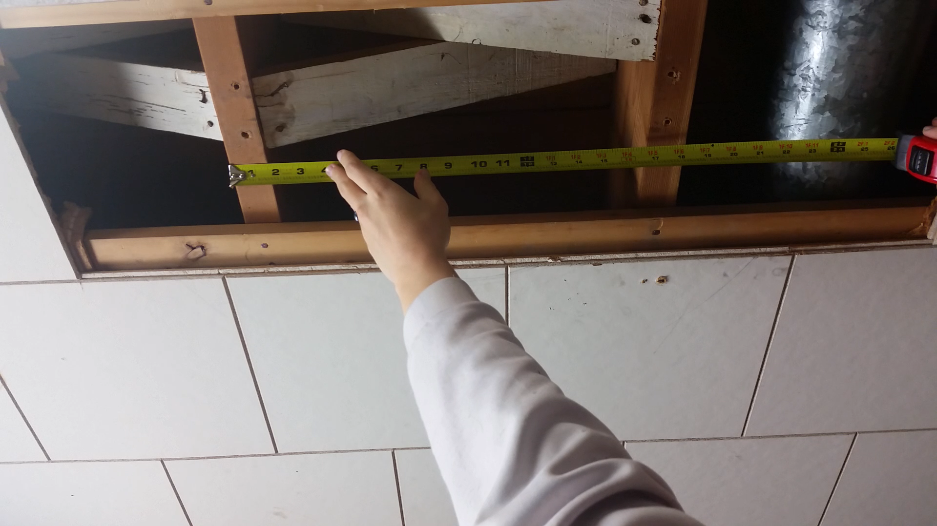
Measure the distance between the beams in your ceiling. If you can't see the beams directly you'll need to use a stud finder.
![]()
Find the distance between the center of one beam to the center of the other. In my case that distance is about 16in, for you it may be different. Also find the distance between the outer edges of each beam. In my case this was about 18in. Remember these two distances.
-
3Cut angle and tube for ceiling brace
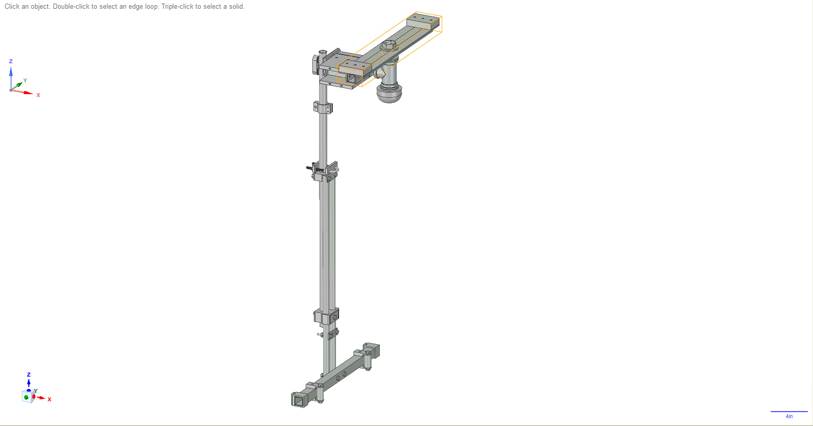
You will be assembling the part of the rig, at the top, that is highlighted in the following image (has the orange lines around it). This is the part that is screwed to the beams in your ceiling.
![]() Take your 1in angle (row 2 in BOM) and cut 2 pieces, each piece should be as long as the distance between the outer edges of each beam. In my case, I cut 2 18in long pieces.
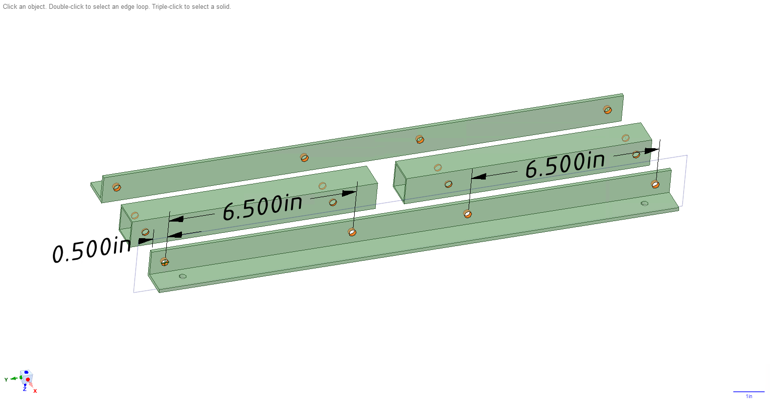
Take your 1in angle (row 2 in BOM) and cut 2 pieces, each piece should be as long as the distance between the outer edges of each beam. In my case, I cut 2 18in long pieces. Take your 1in square tube (row 4) and cut 2 pieces. If X represents the length of your angle pieces (18in in my case), then each square tube will be of length (X/2 - 0.5)in. So in my case, 8.5in. You will end up with something like the following image, only that your lengths may be different. Ignore the holes in the pieces for a second, we'll get to that. You are going to want a 1in square hole in the middle of the brace as I show in the image, which is how I derived the (X/2 - 0.5)in equation.
![]()
-
4Drill holes in pieces of ceiling brace
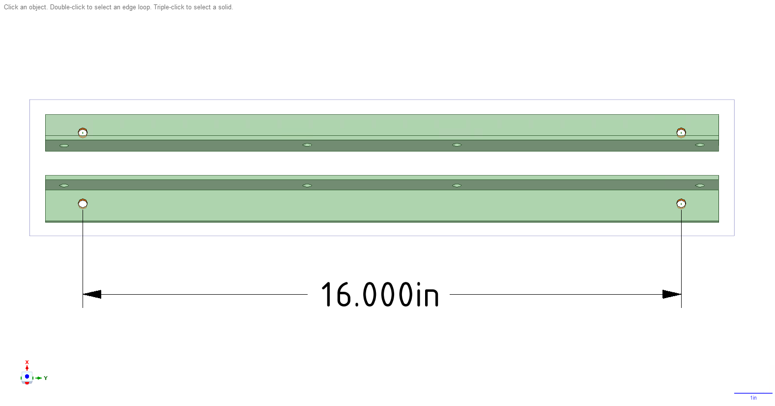
Using the the center of one beam to the center of the other distance you found earlier, in my case 16 in, you're going to drill holes in the 2 angle pieces. Drill the holes as shown in the image below (the holes you should drill are highlighted in orange). These are the holes you will put lag screws through to secure the whole rig to the ceiling. I used 1/4in lag screws, so these 4 holes you drill can be a minimum of 1/4in in diameter. I drilled 5/16in holes so that it would be slightly easier to screw the lag screws in later.
![]()
Next, drill the set of holes highlighted in orange in the below image. You will soon put hex bolts through these holes to fasten the angles and square tubes together into one piece. I used 1/4in hex bolts, so the minimum diameter for these holes is again 1/4in. I again used a 5/16in drill bit so that it was easier to put the hex bolts through.
![]()
-
5Assemble brace
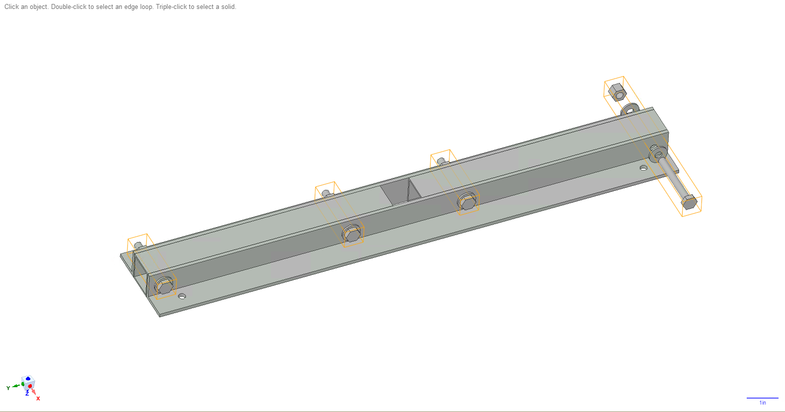
Take 1/4in hex bolts, 2 in long (row 5), 1/4in lock nuts (row 6), and 1/4in washers (row 7), and use them to screw the angles and square tubes together as shown in the following image. Notice that I have a washer on each side. You should use 4 bolts, 4 lock nuts, and 8 washers.
![]()
-
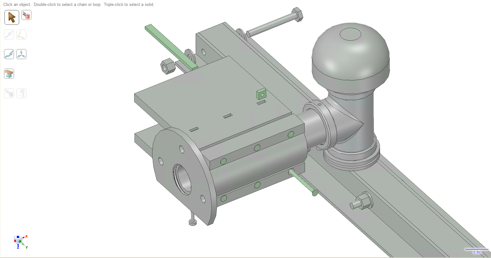
6Assemble swivel arm
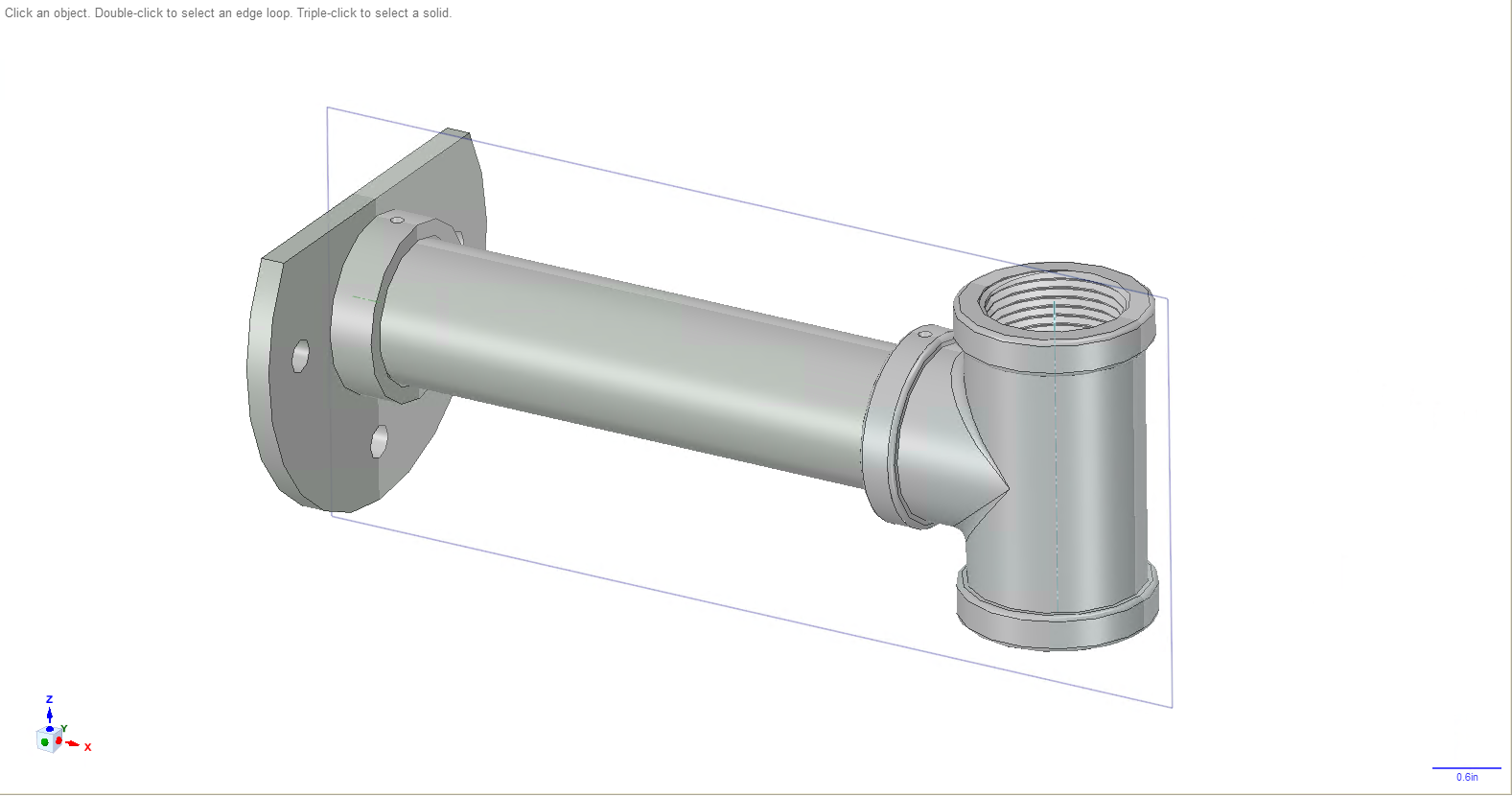
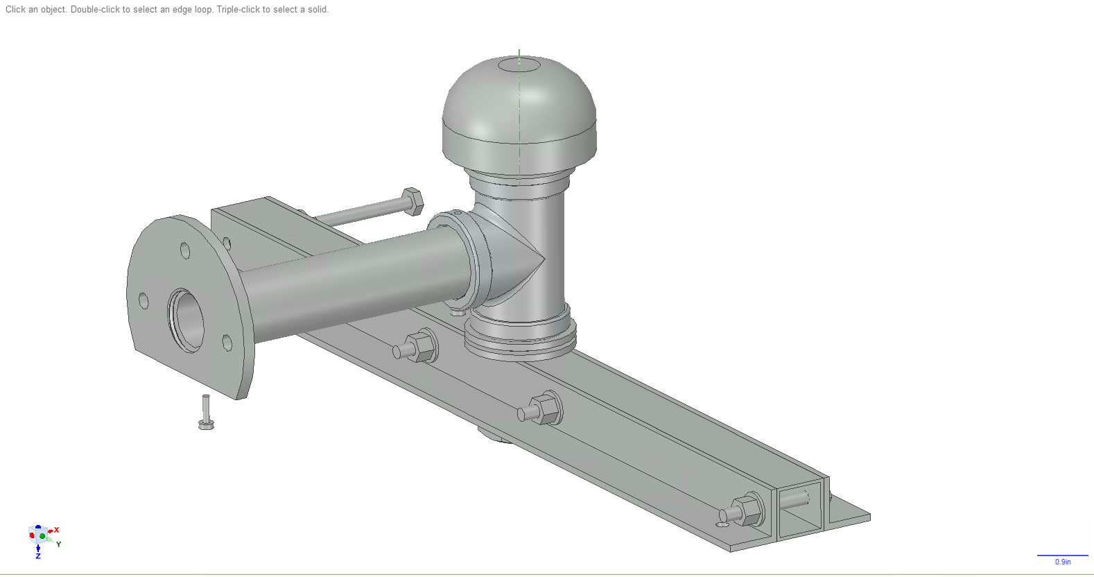
You are now going to be assembling the swivel arm, which consists of a pipe flange (row 22), pipe (row 21), and pipe tee (row 20), as shown below highlighted with the orange lines.
![]()
For the pipe flange, put cut the top of it off as shown below. Cut as close to the orange highlighted part (the outer perimeter of the threads I guess you'd call it) as you can.
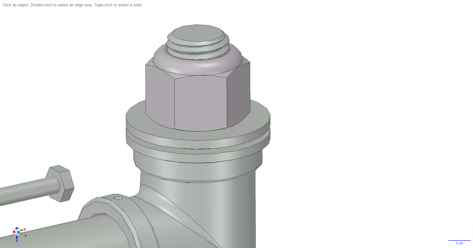
Screw the flange, pipe, and pipe tee together as shown below. Notice how the bottom hole of the pipe flange lines up with the plane, and notice how the pipe tee is running along the plane. You want to make sure the flange and pipe tee are aligned along the plane. Double and triple check that the pieces are lined up.
![]()
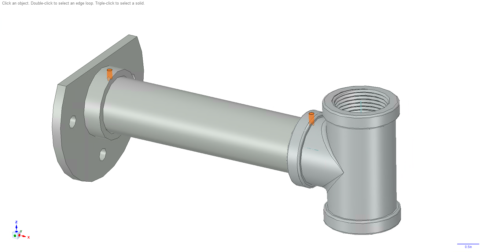
Try to screw these pieces tightly together so that this arm will be rigid. You may be unscrewing these pieces later, but first take a marker and mark some lines on the pipe, flange, and pipe tee such that when you screw them back together you can line up the marks on the 3 pieces.
Screw 2 holes, as highlighted in the image below. The diameter of these holes is 1/8in. You want these holes to go all the way through the pipe as well.
![]()
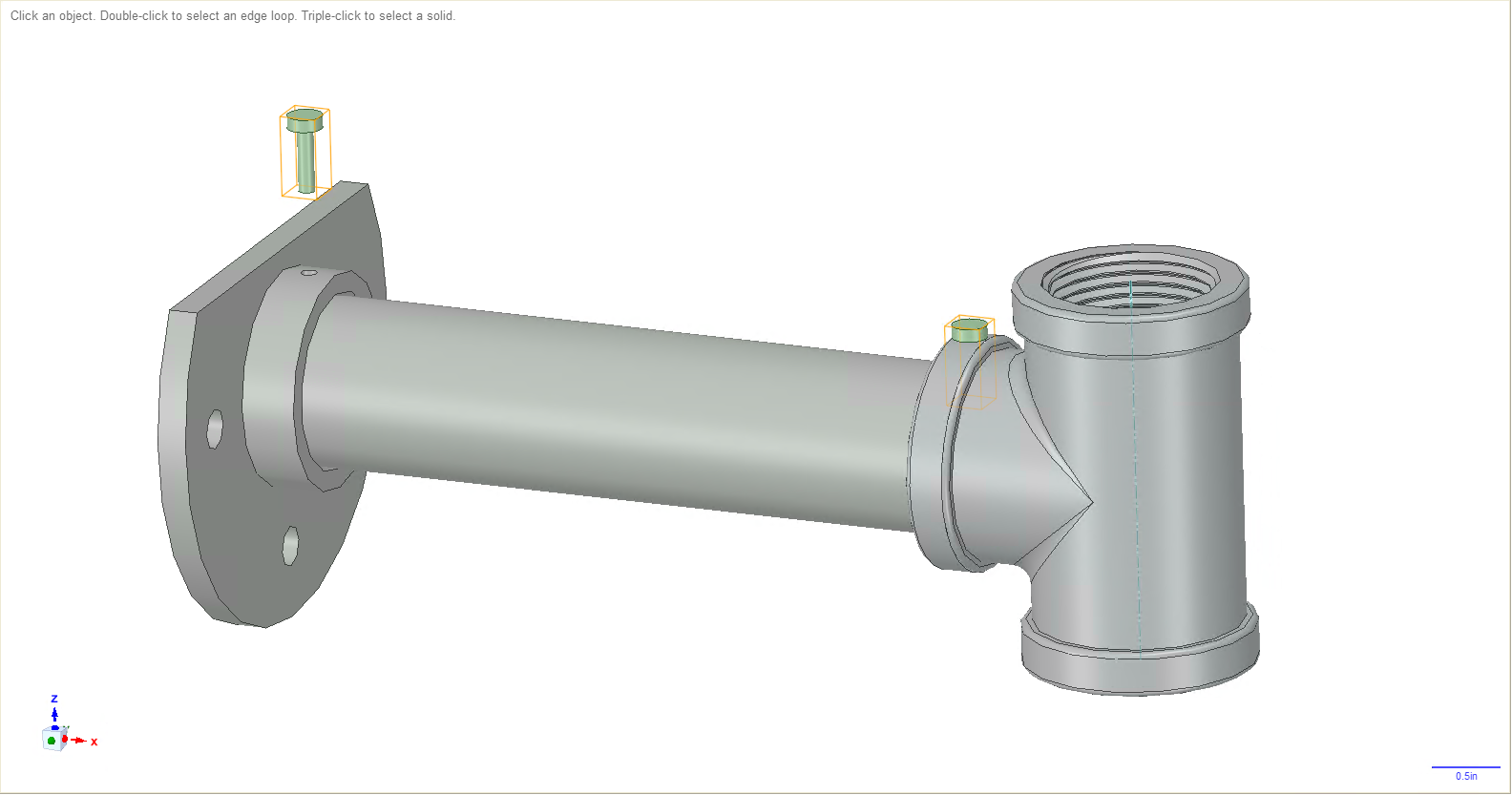
If you'd like you can now unscrew these three pieces, take some epoxy (row 17) and smear it on the threads, then screw the pieces back together. Once the epoxy dries these three pieces should not be able to loosen from each other. Or, you can skip this part and just rely on the 2 screws that will be hammered into the two 1/8in holes you just drilled. Those should be enough to make sure these parts do not loosen, but I used both screws and epoxy in my build, which was probably overkill.
Take 2 6-32, 1/2in long screws (row 19) and hammer them into the 2 holes you just drilled, as shown in the following image.
![]()
-
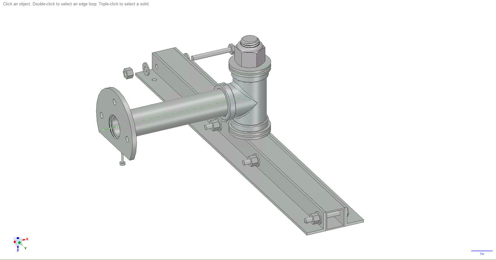
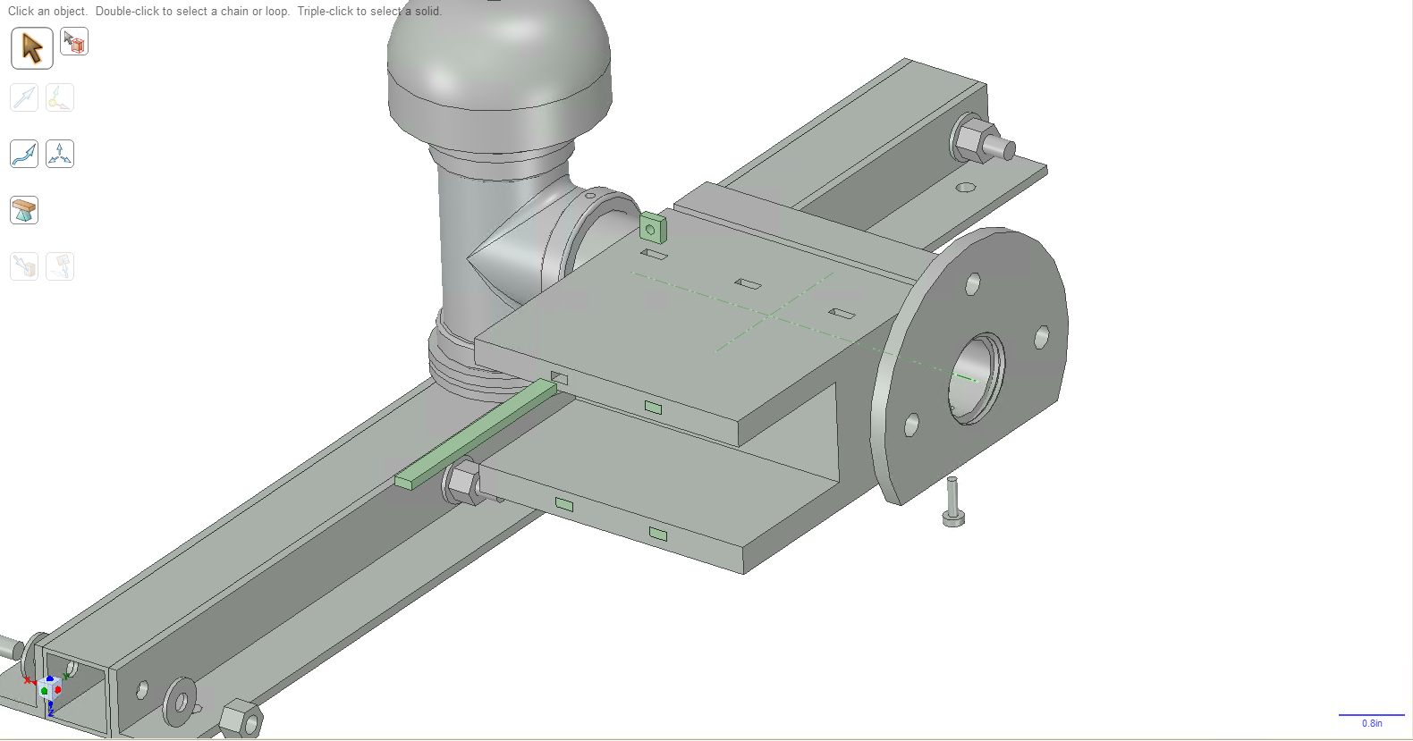
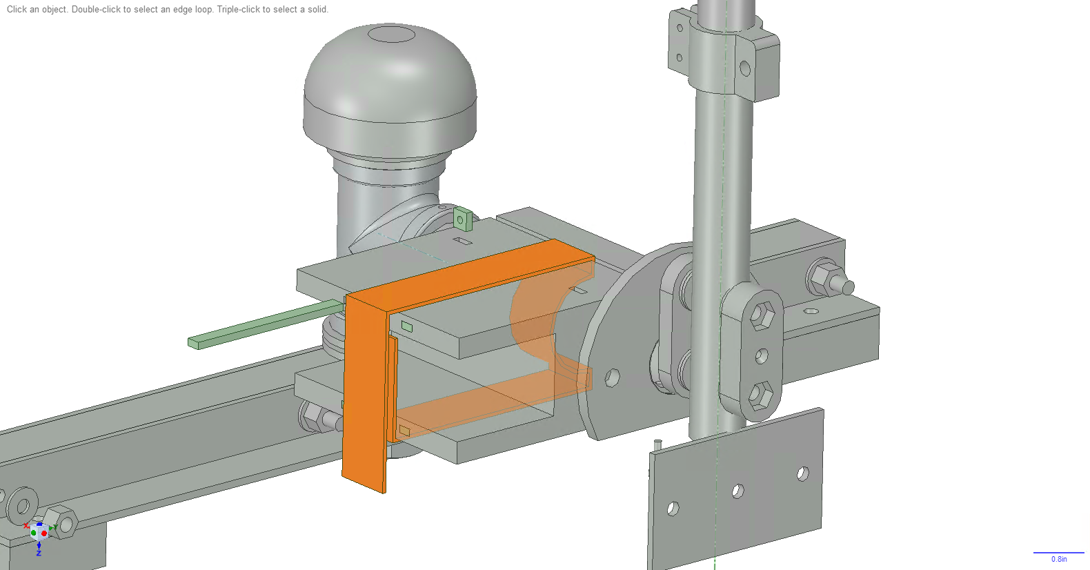
7Assemble the swivel
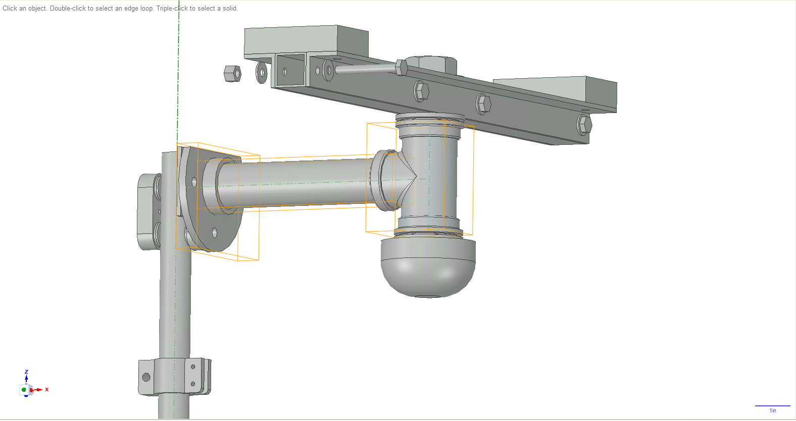
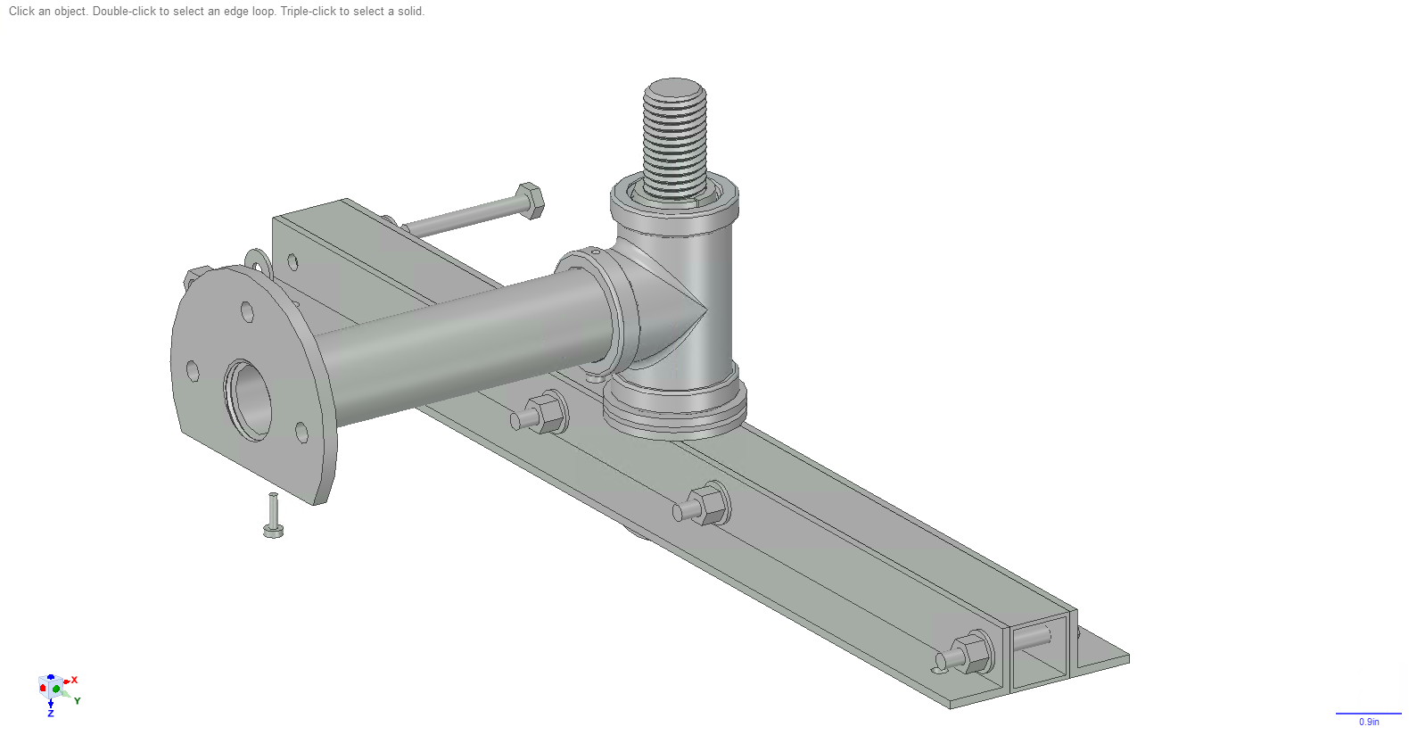
You'll now be assembling the rest of the swivel and coupling it to the ceiling brace, as shown in the following image.
![]()
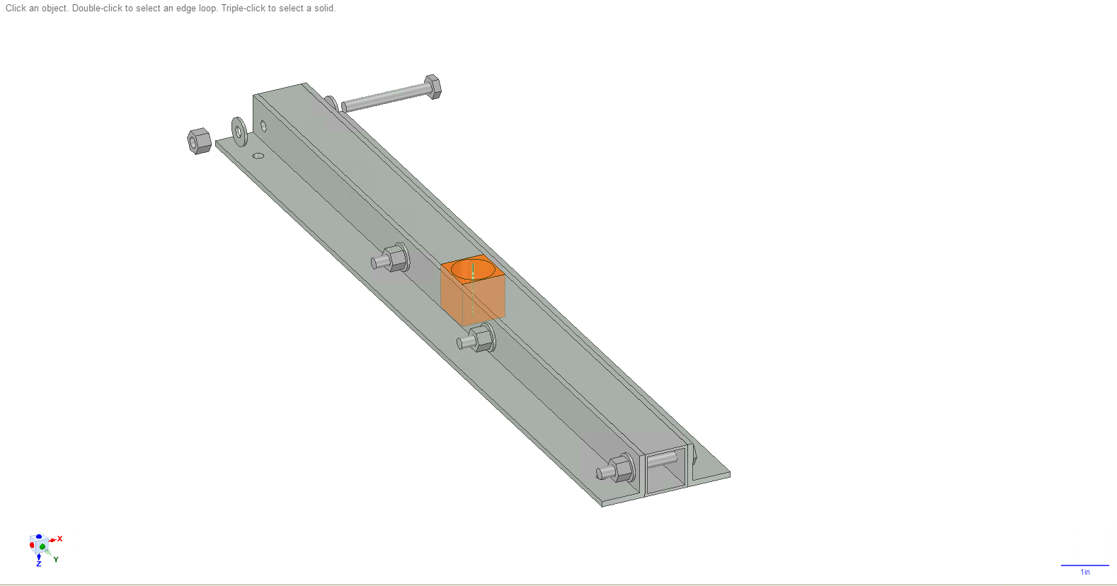
Take the 3D printed square spacer for the ceiling brace (row 16) and insert it into the brace. It is highlighted in orange below.
![]()
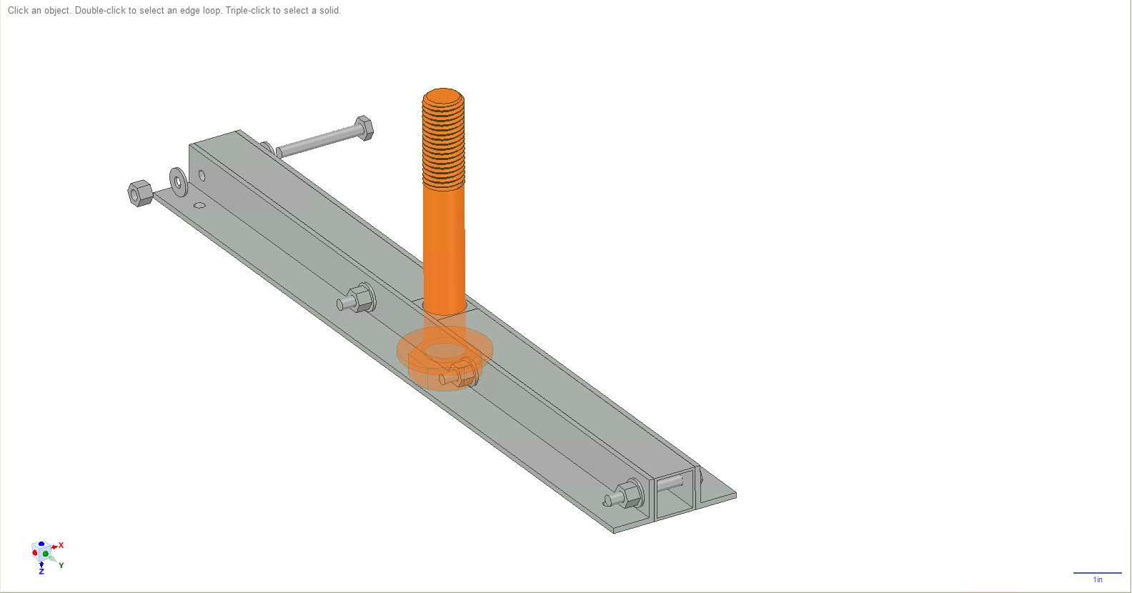
Take your 7/8in, 6in long bolt (row 9), and a 7/8in washer (row 11). Slide the washer onto the bolt. Put the bolt through the ceiling brace as shown below.
![]()
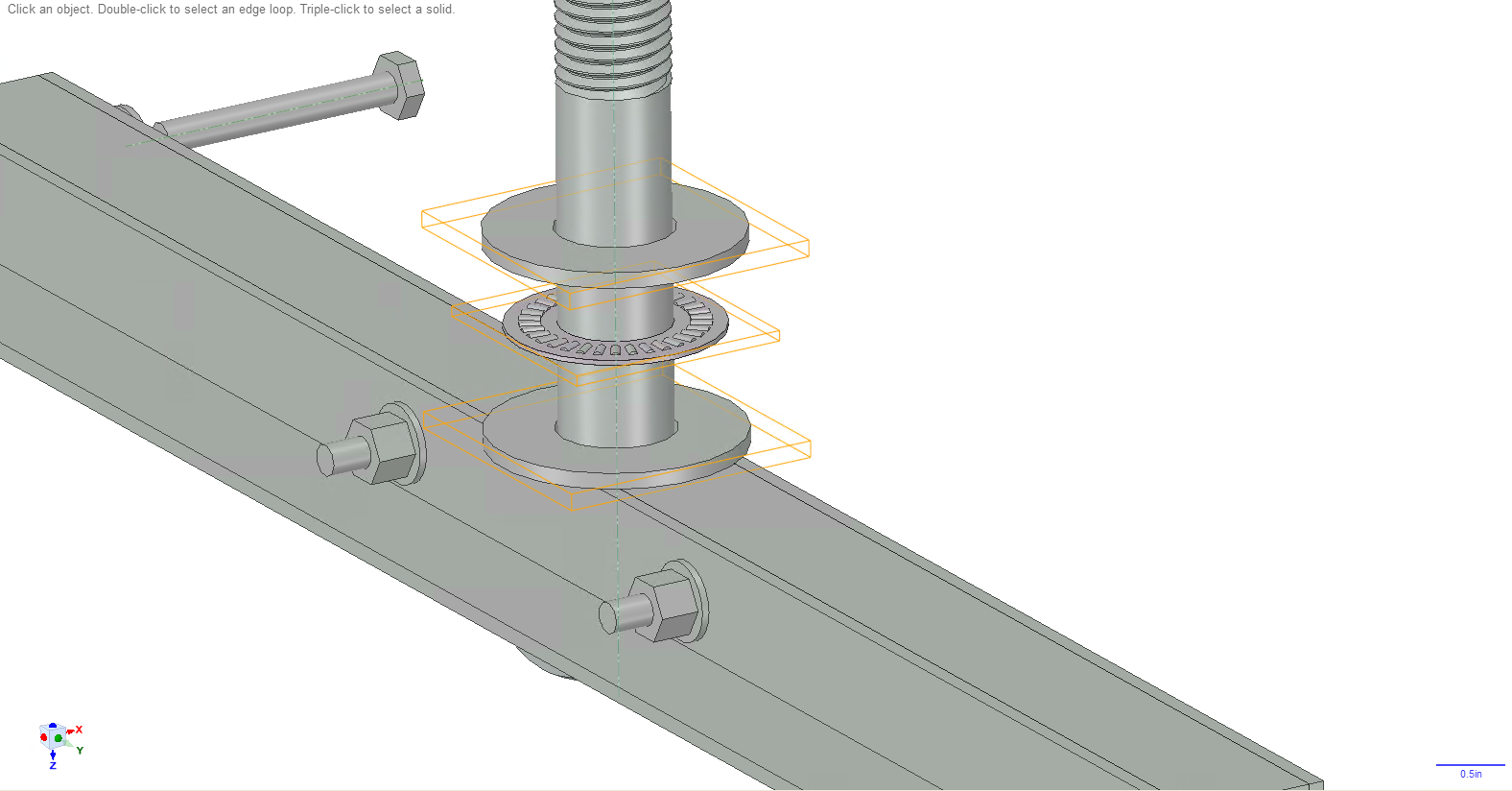
Slide a washer onto the bolt, followed by another thrust bearing (row 12), followed by another washer. You may want to put some grease (row 18) on the thrust bearing to ensure the assembly will swivel well.
![]()
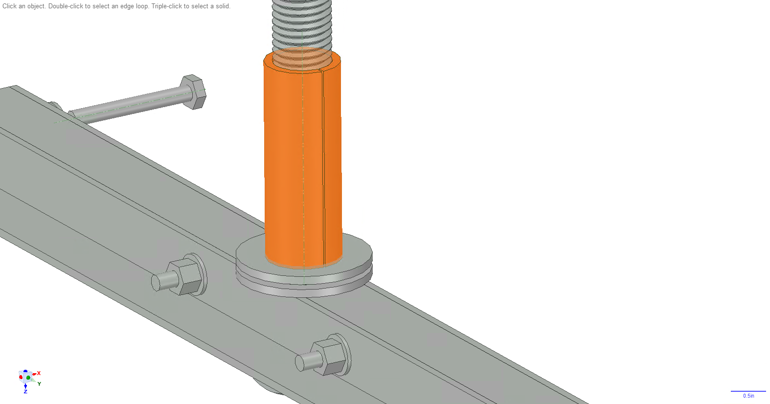
Put some grease on the bolt. Take the 3D printed pipe tee spacer (row 13) and slide it over the bolt. Then put some grease on the outside of the spacer.
![]()
Put the swivel arm onto the bolt.
![]()
Put another washer, thrust bearing, and washer onto the bolt. Again grease the thrust bearing. The screw the 7/8in lock nut (row 10) onto the bolt.
![]()
I had to put the head of the bolt into my vice, then take a pipe wrench and screw the lock nut on. You should screw it on at least enough so that the swivel arm does not wiggle at all if you swivel it around the bolt and pull on it in any direction. You do not want any play or wiggling at all. You can continue to screw the lock nut tighter so that there is some resistance to the swivel arm rotating around the bolt. Even with that resistance it will be very easy for you to turn the rig, as the swivel arm gives you more than 6in of leverage and you will be turning using your hip and leg muscles, which should be more than strong enough to overcome some resistance. Again, the important thing is to eliminate all play, even when there is weight on the end of the swivel later on.
Take the 3D printed lock nut cover (row 14) and slide it over the 7/8in bolt.
![]()
-
8Add storage clamp
This part is optional. You can add a clamp that goes onto the swivel that will later allow you to store the entire rig up at the ceiling.
![]()
3D print the clamp pieces (rows 27 and 28). Take your 1/4in by 1/8in rectangular bar (row 30) and cut 4 3in pieces. Slide them into the holes in the clamp. Also take 6-32 square nuts (row 29) and slide them into the 6 slots.
![]()
If the bar or nuts fall out, you can take some super glue and put a little bit on the bar or nut and insert it and wait for the glue to dry.
You will be taking the clamp and tightening it down around the pipe on the swivel arm, as shown below. Notice that you'll use 6-32, 2in long screws (row 31) to tighten it. Don't do this yet.
![]()
You'll want to take a velcro strap (row 26) and thread it inside the clamp as shown below. I used about a 6in long piece.
![]()
-
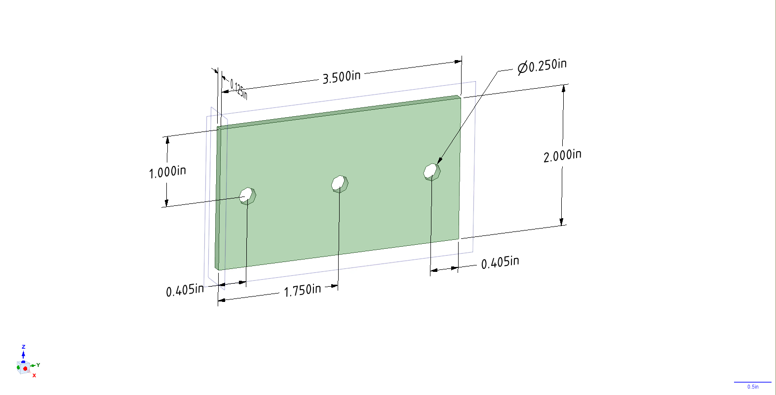
9Assemble end of swivel
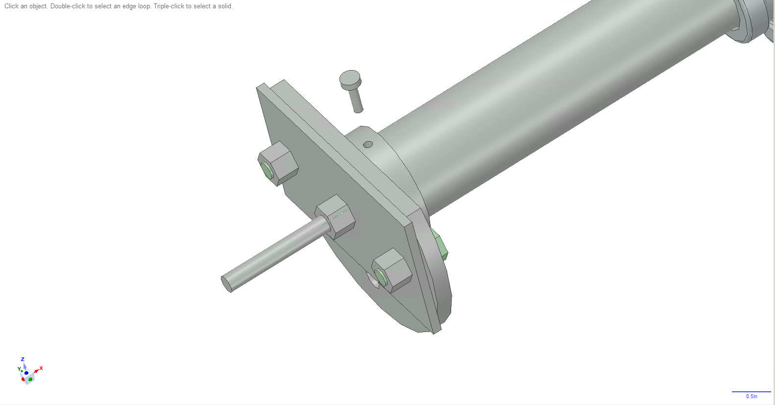
Take your 1/8in thick, 2in wide, 36in long solid flat (row 23) and cut a 3.5in long piece off of it. Drill 3 holes in it according to the dimensions in the following image.
![]()
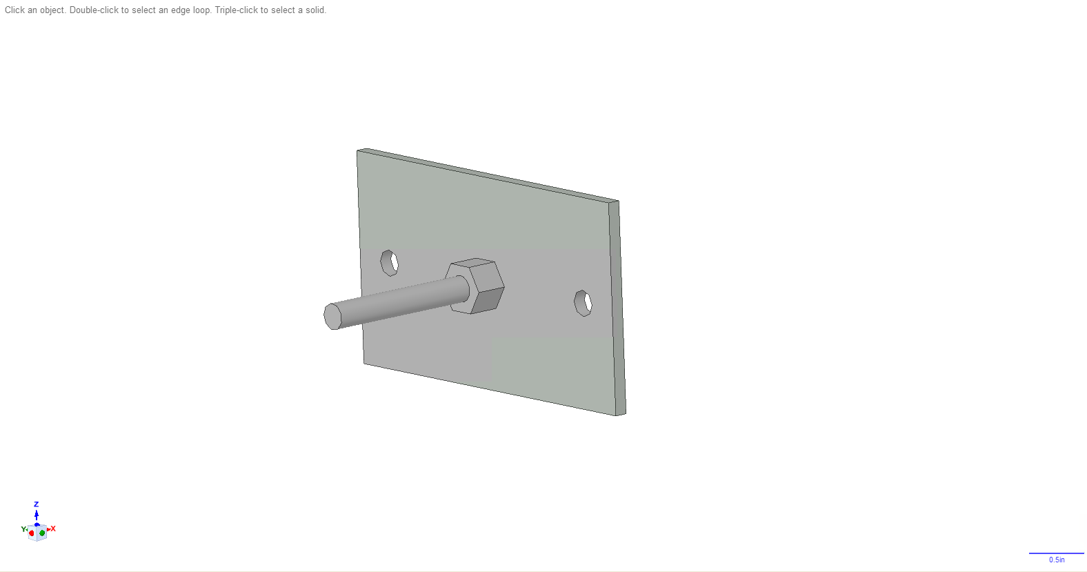
Take a 1/4in, 2.5in long fully threaded hex bolt (row 25) and put it through the middle hole. Then take a lock nut and tighten it all the way down on the other side of the flat. Tighten this nut and bolt as hard as you can.
![]()
Take 2 1/4in, 3/4in fully threaded hex bolts (row 24) and use them to secure the flat to the pipe flange as shown below. I also used 2 washers for each bolt.
![]()
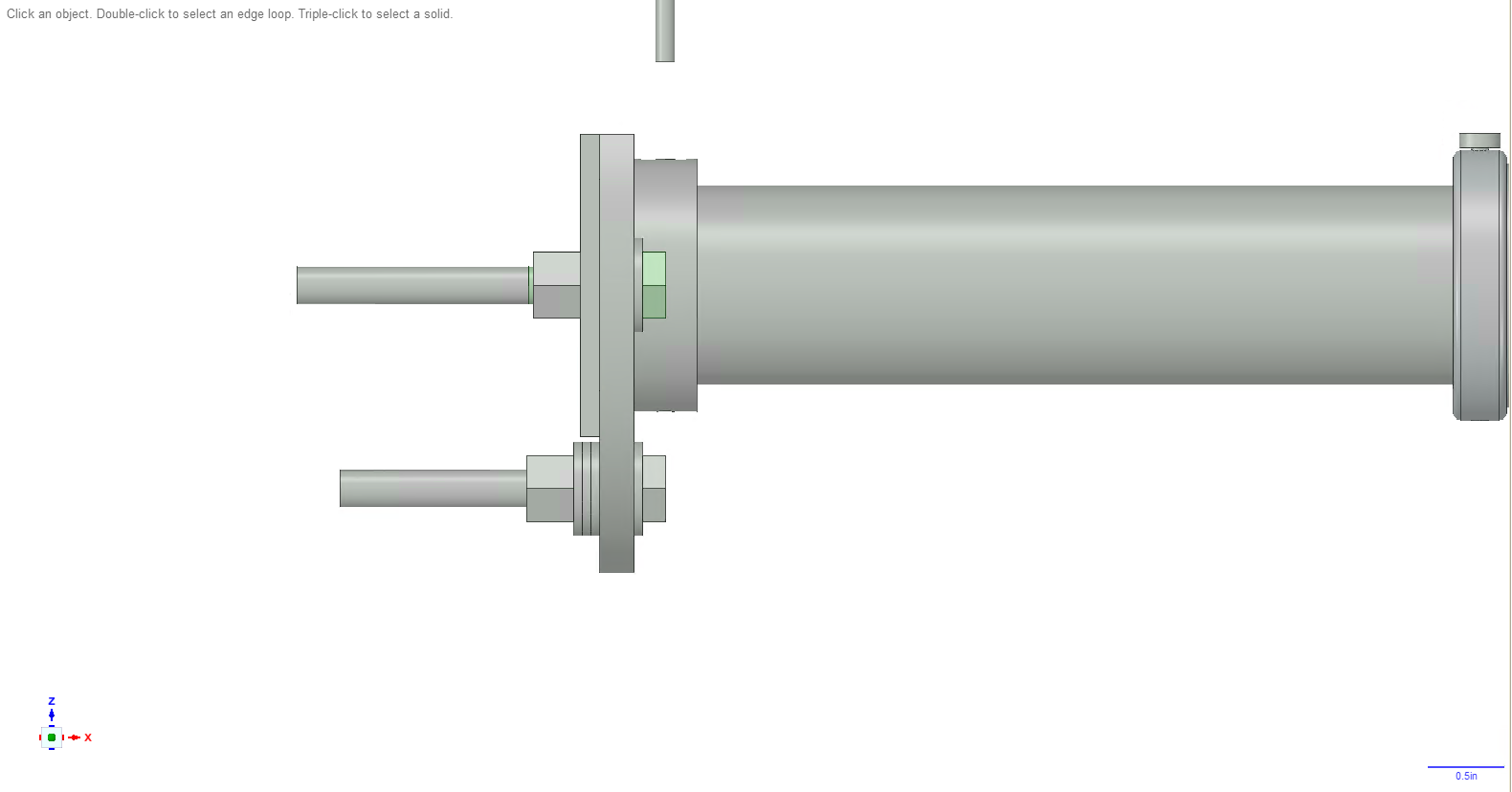
Take another 2.5in long, fully threaded bolt, put a washer on it, and slide it through the bottom hole of the pipe flange. On the other side of the flange, slide 3 washers on. Then screw a lock nut on, again tightening this as much as you can.
![]()
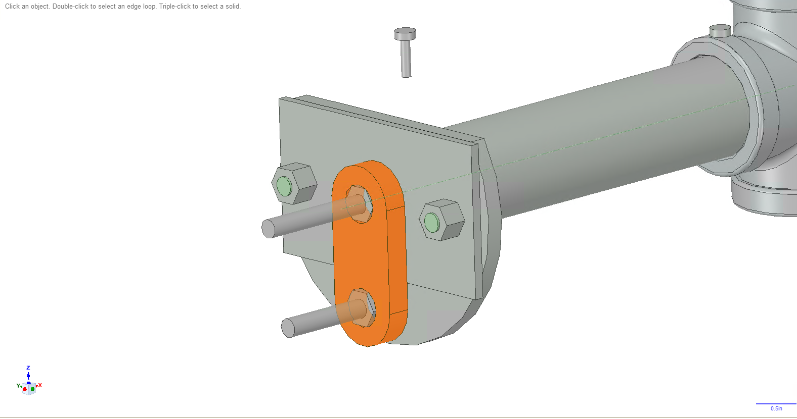
Take the 3D printed spacer for the 2 bolts (row 33) and slide it on.
![]()
-
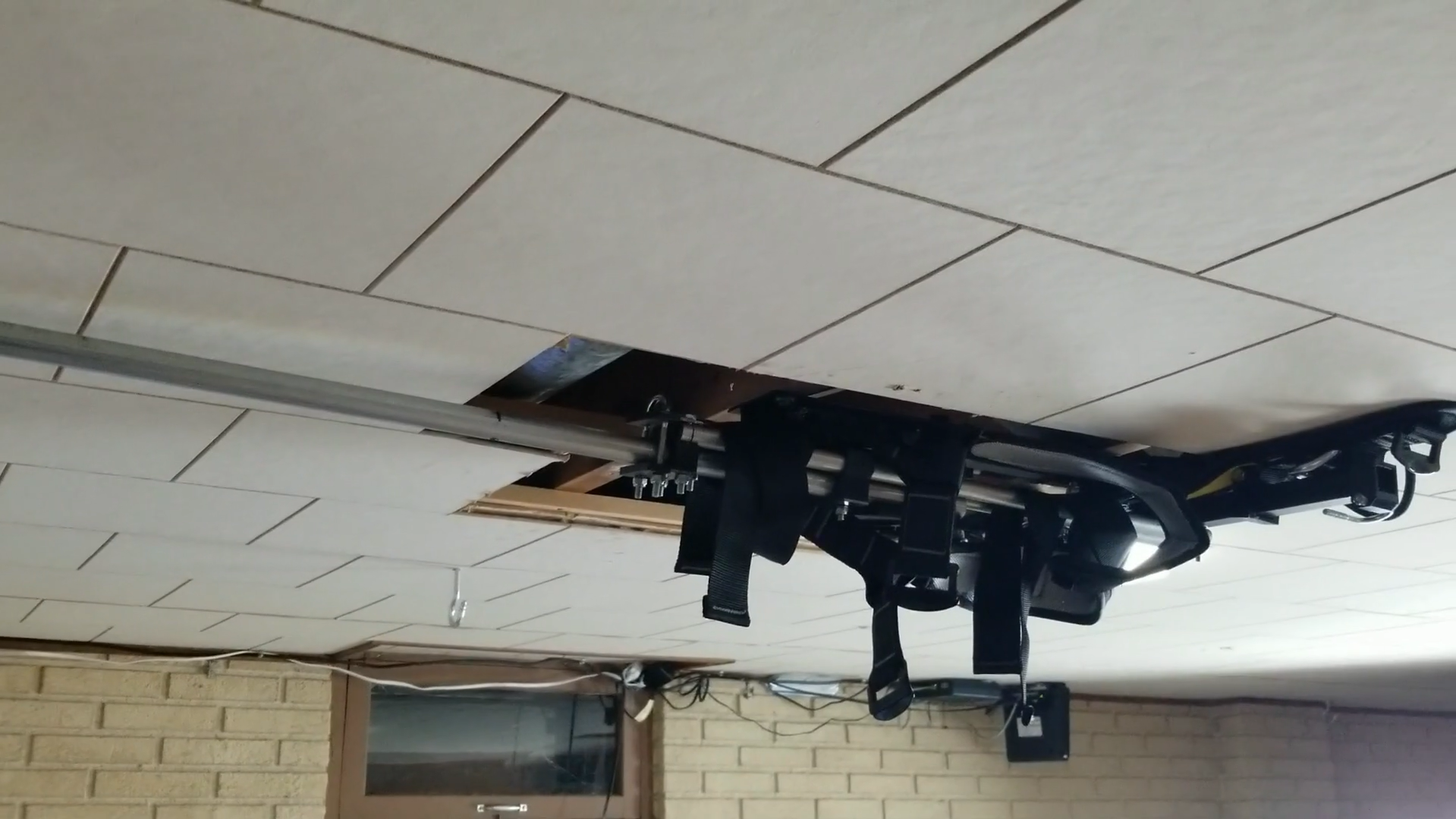
10Screw to the ceiling
Screw the assembly to the ceiling. Please follow the instructions in the following videos.
Ceiling Mounted VR Support Rig
A support rig for VR to keep you in the same spot in real life as you walk in VR. Use this with my VR shoes.
 Take your 1in angle (row 2 in BOM) and cut 2 pieces, each piece should be as long as the distance between the outer edges of each beam. In my case, I cut 2 18in long pieces.
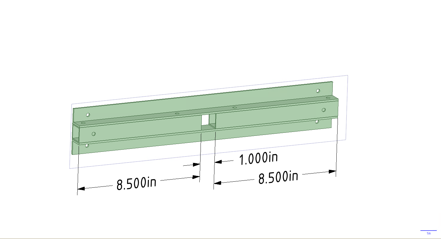
Discussions
Become a Hackaday.io Member
Create an account to leave a comment. Already have an account? Log In.