 ASHUMHRPROJECTS
-
1Step 1
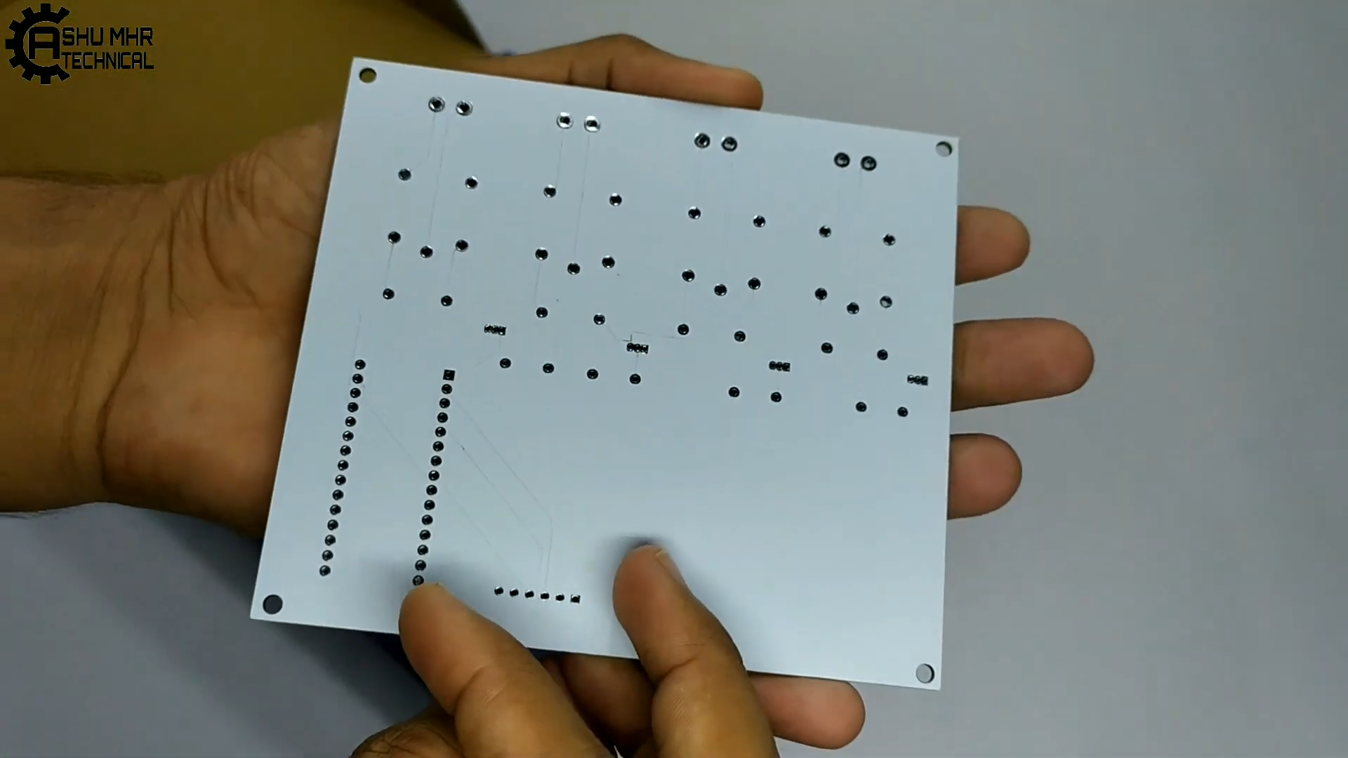
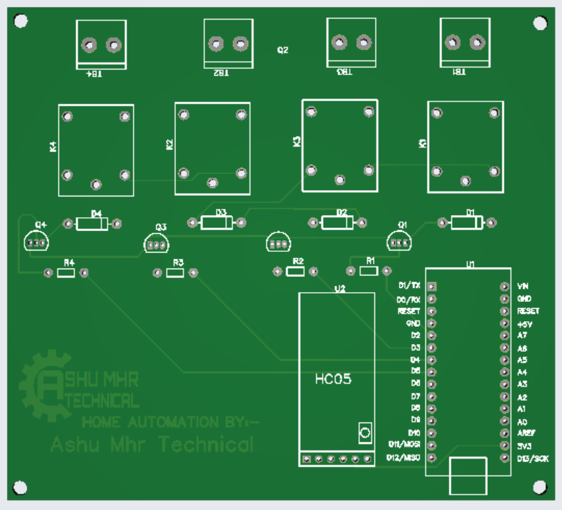
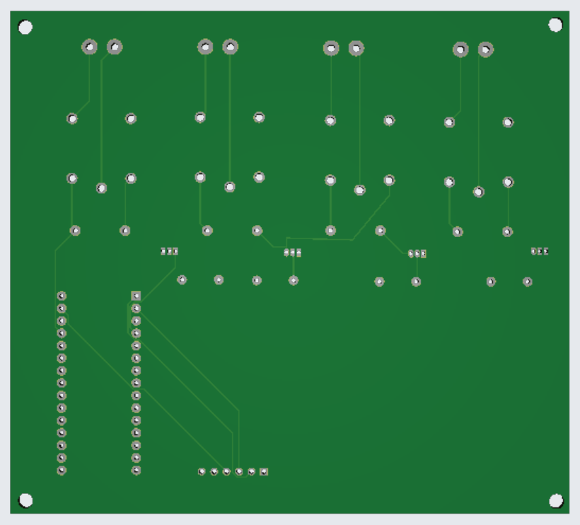
Step 1: Get your PCB ready!
Talking About Electronics
- After making the circuit diagram I transformed it into a PCB design to produce it, to produce the PCB, I have chosen JLCPCB the best PCB supplier and the cheapest PCB provider to order my circuit. with the reliable platform, all I need to do is some simple clicks to upload the Gerber file and set some parameters like the PCB thickness color and quantity. I’ve paid just 2 Dollars to get my PCB after five days only, what I have noticed about JLCPCB this time is the "out-of-charge PCB color" which means you will pay only 2 USD for any PCB color you choose.
![]()
![]()
![]()
![]()
![]()
Related Download Files
- As you can see in the pictures above the PCB is very well manufactured and I’ve got the same PCB design that we’ve made for our main board and all the labels and logos are there to guide me during the soldering steps. You can also download the Gerber file for this circuit from the download link below in case you want to place an order for the same circuit design.
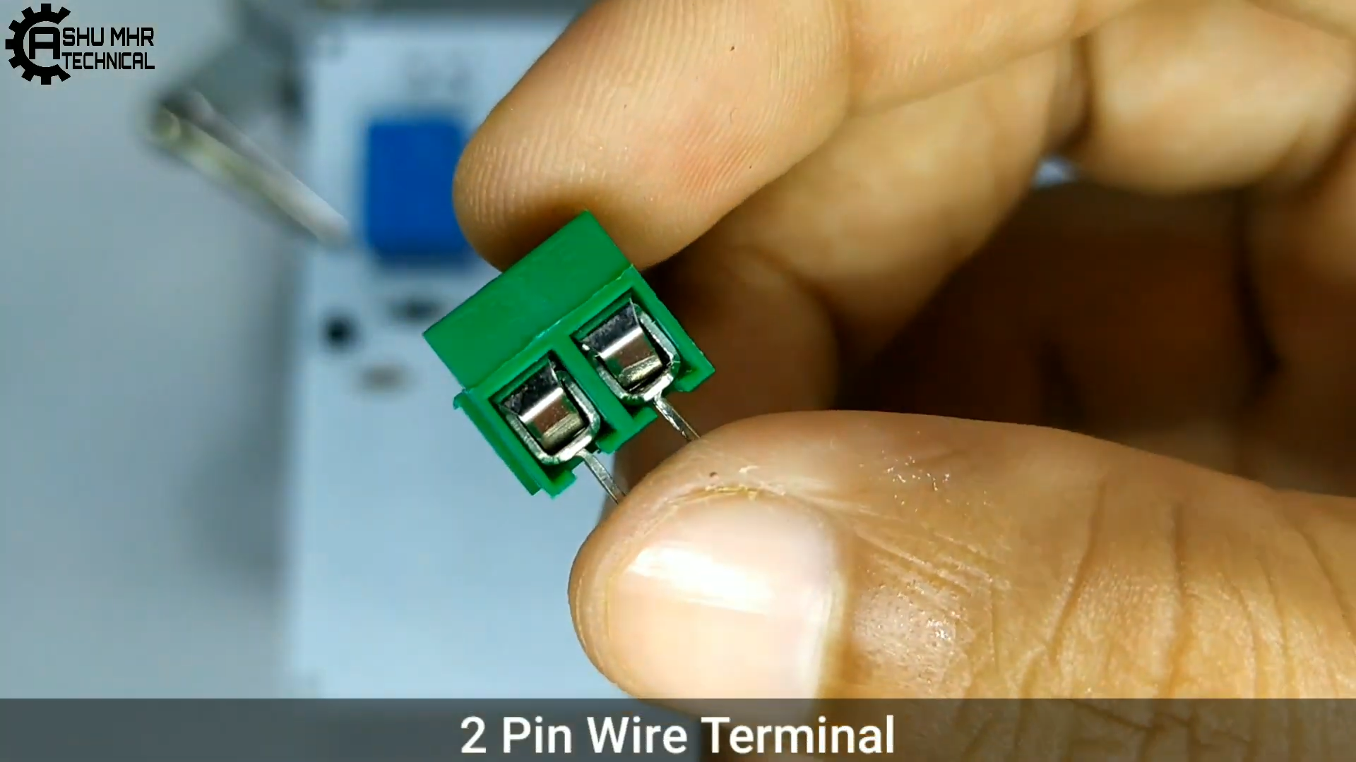
Step 2: Get all the Components Listed below images.
![]()
![]()
![]()
![]()
![]()
![]()
![]()
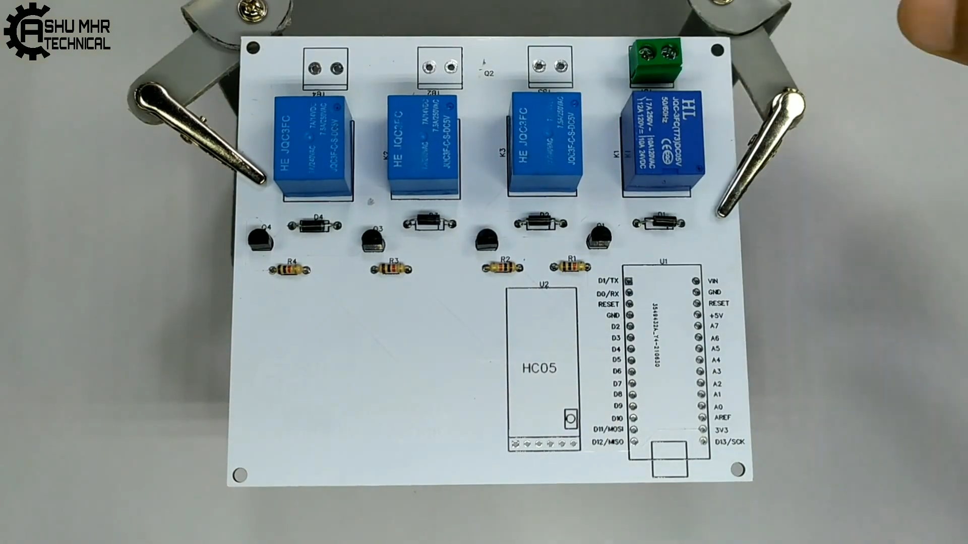
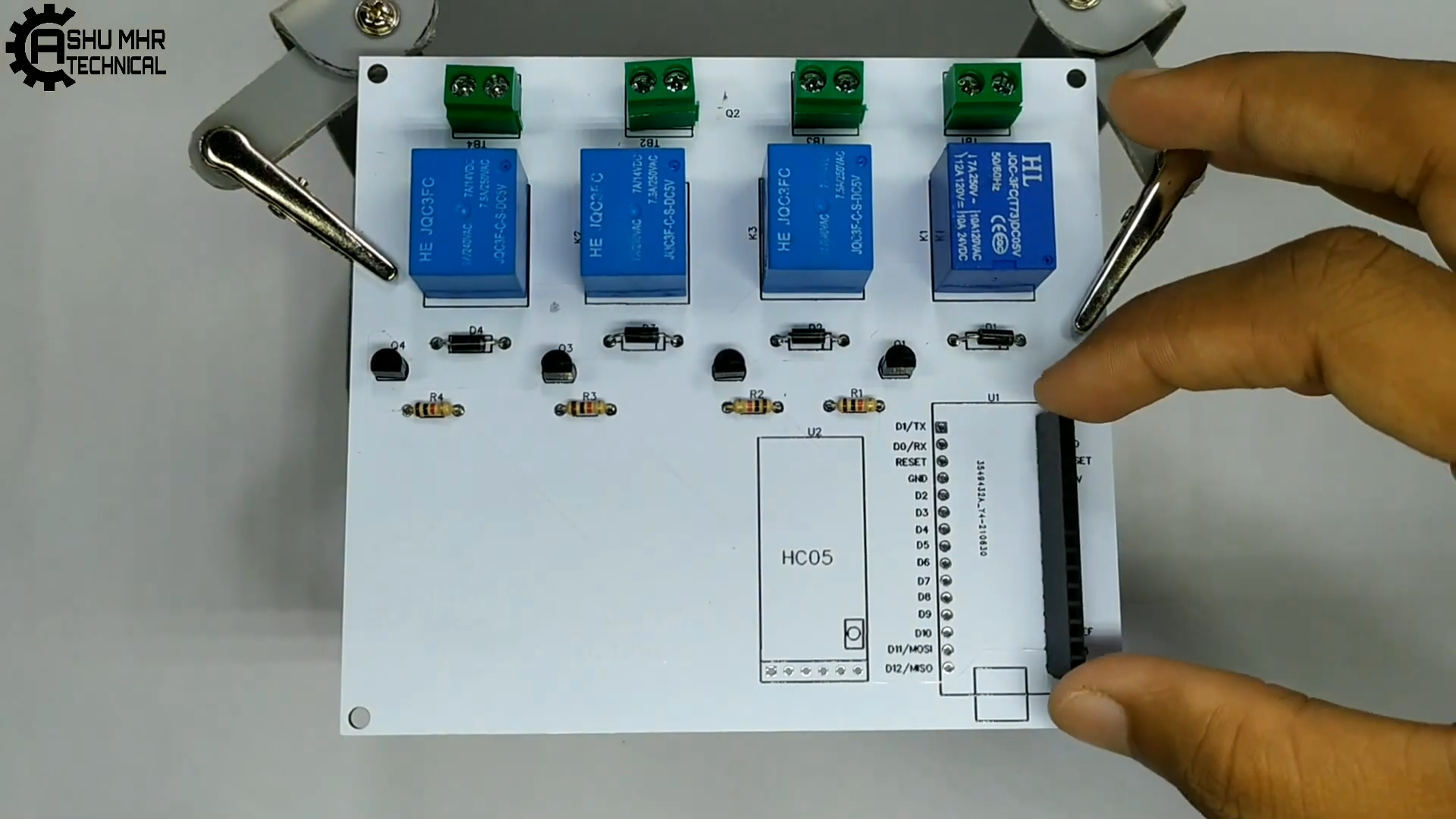
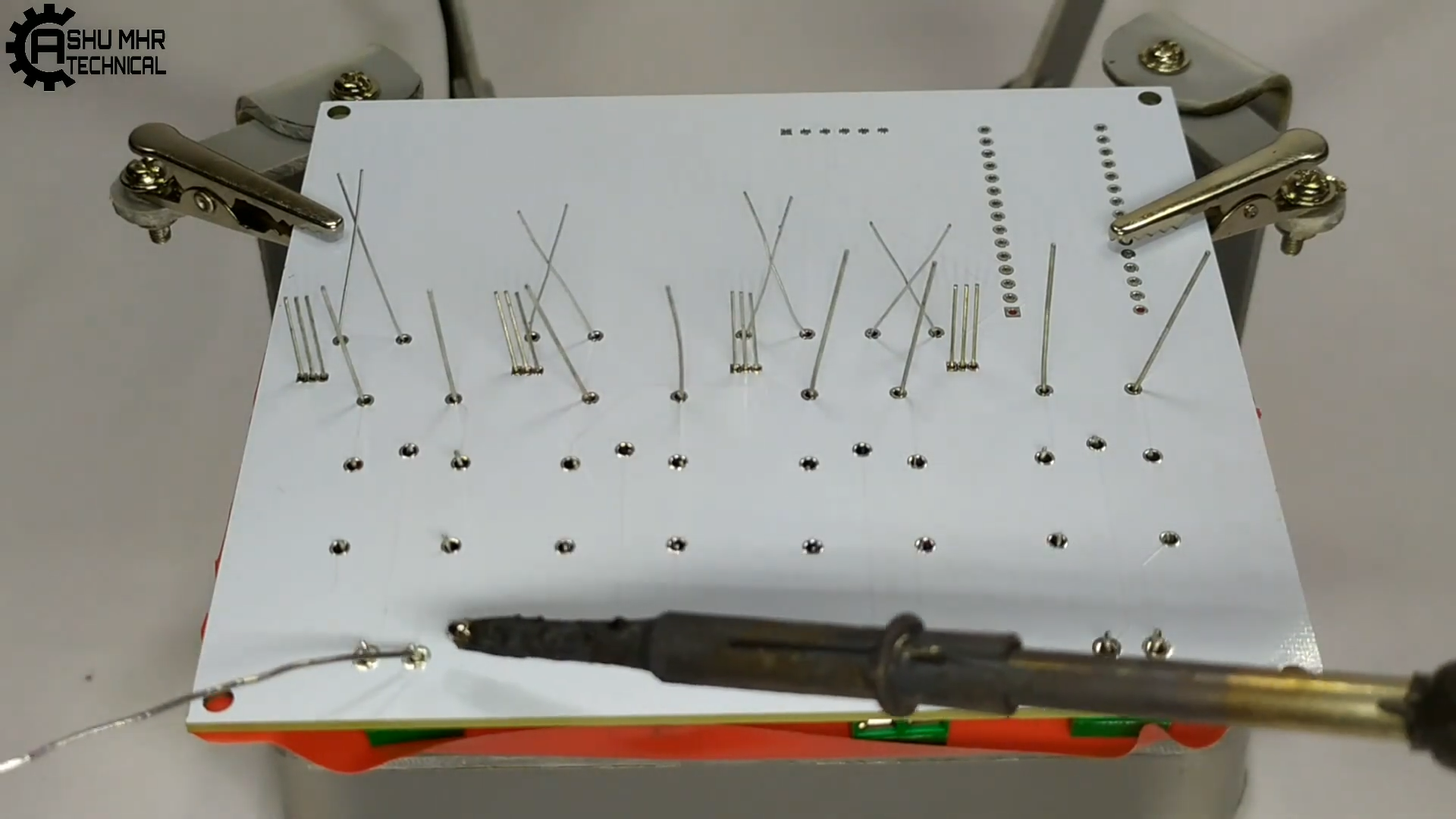
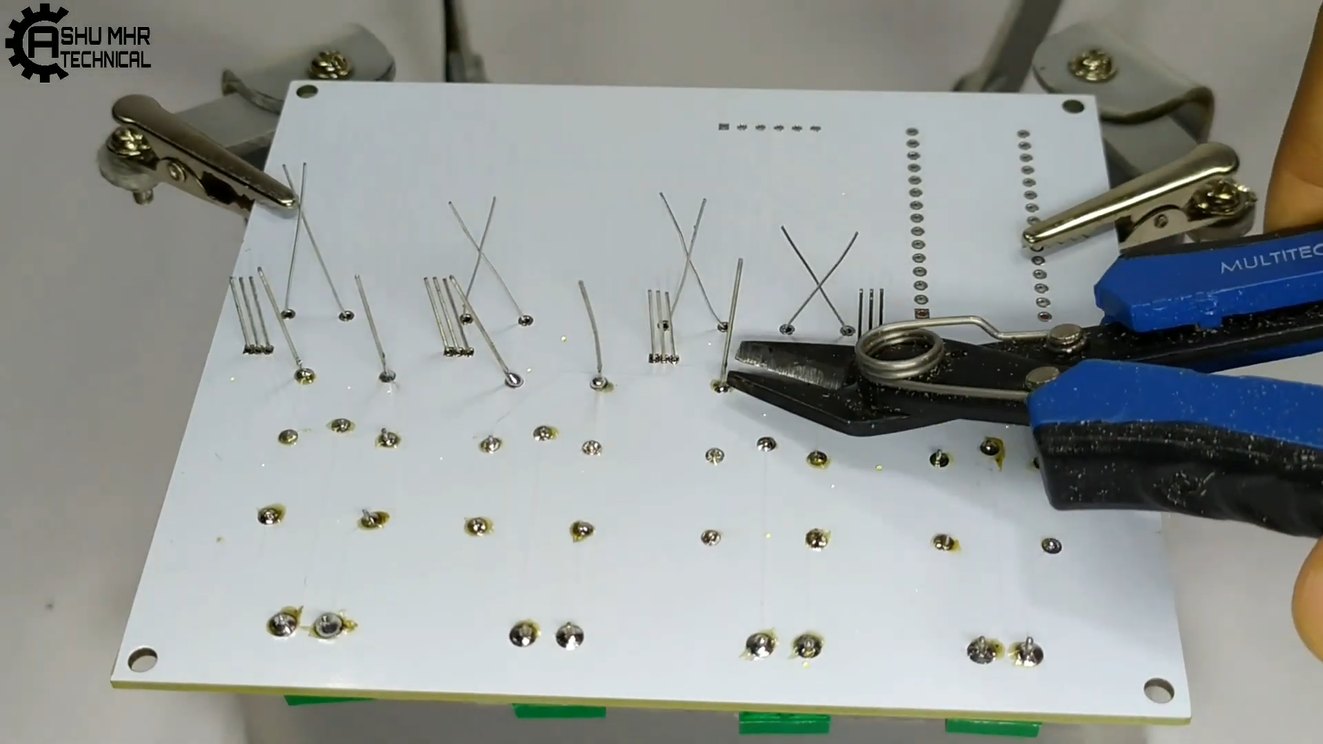
Step 3: Place all the components on PCB and solder it properly.
![]()
![]()
![]()
![]()
![]()
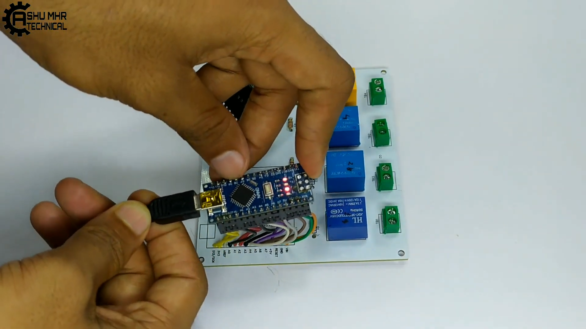
Step 4: After soldering all the components to PCB, connect Arduino nano to your PC(use Arduino IDE) / Phone(use ArduinoDroid) and upload the code.
![]()
![]()
![]()
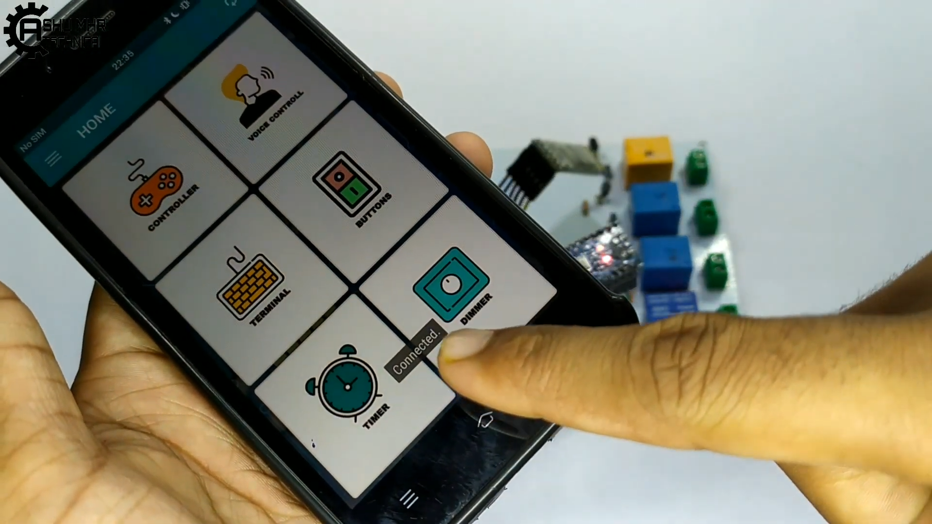
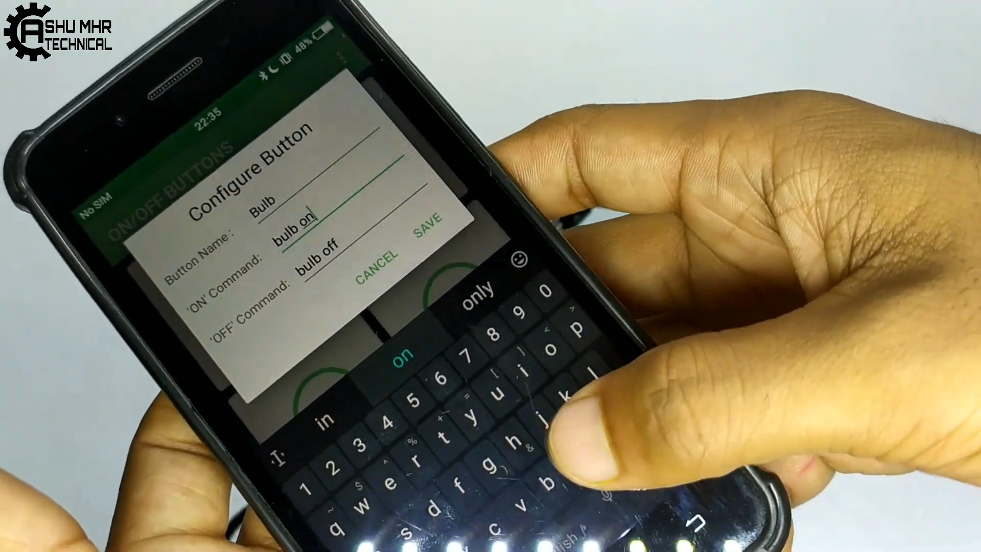
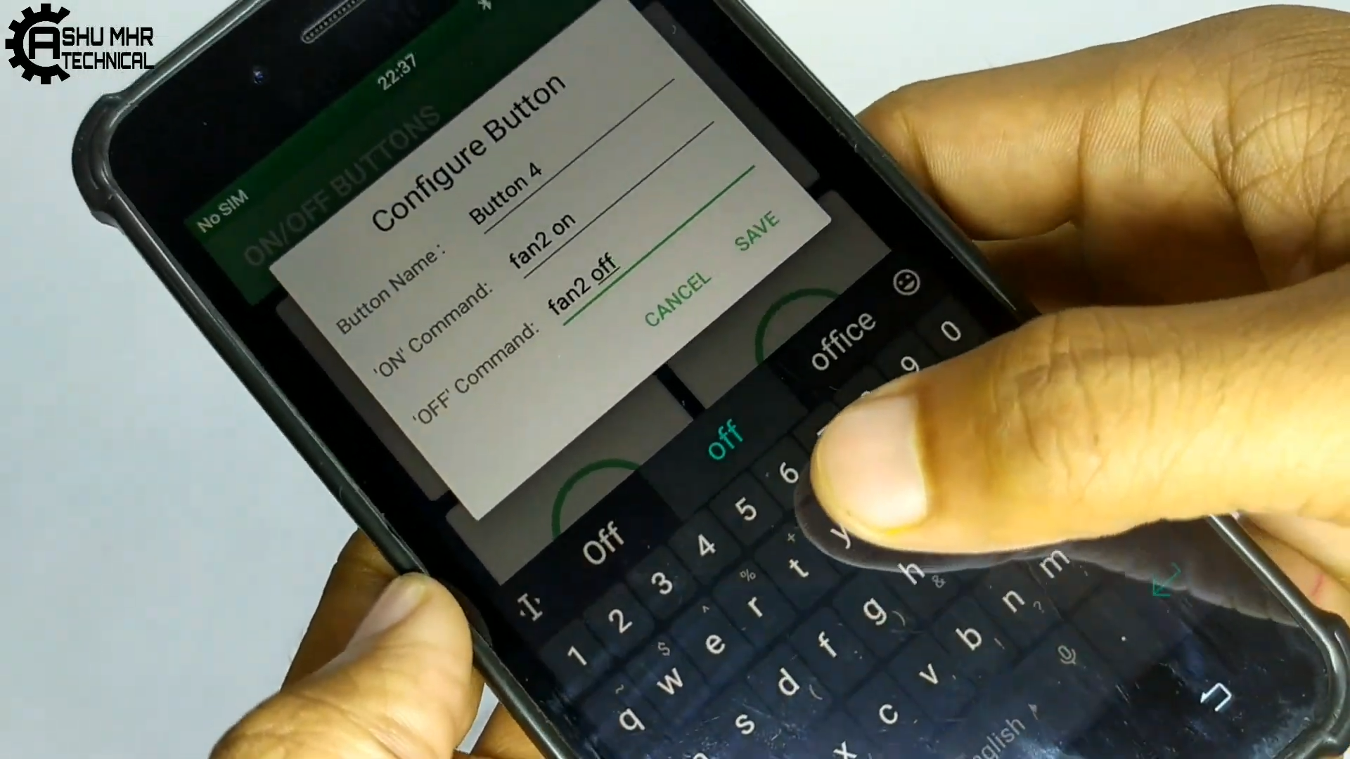
Step 5: Download Arduino Bluetooth Controller from Play Store.
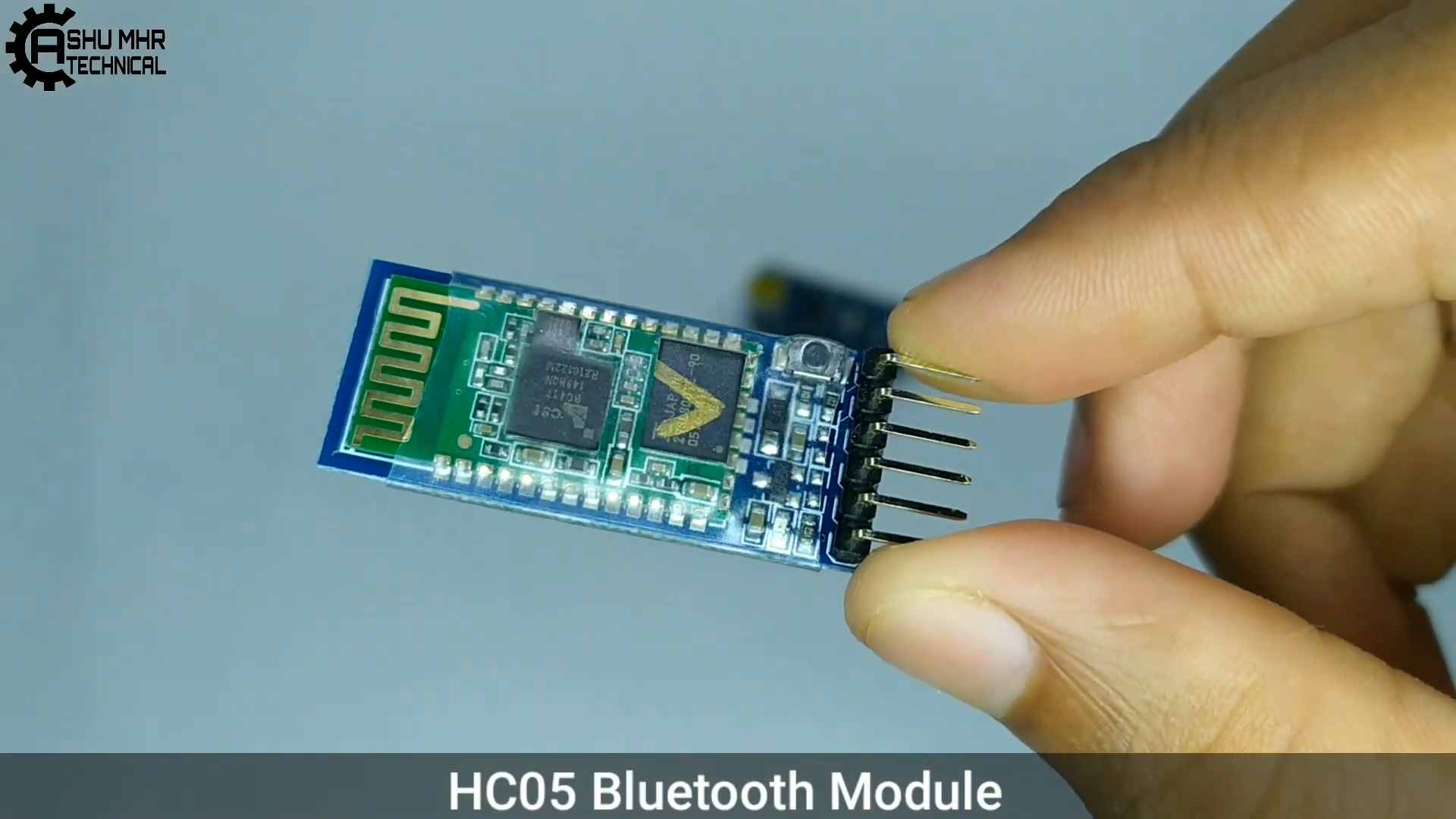
- Turn ON the Bluetooth, pair the HC-05 Bluetooth module to the phone(usually the password is "1234" for the HC-05 Bluetooth module).
- After pairing the Bluetooth module open the Arduino Bluetooth control app and connect HC-05.
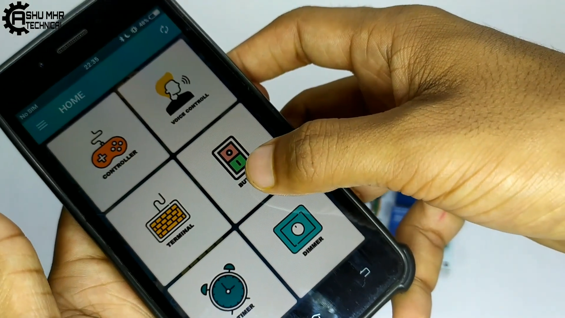
- Tap on the button icon, then tap on Button 1 and change the button name and ("ON"-"OFF")Command as shown in the images below.
![]()
![]()
![]()
![]()
![]()
![]()
![]()
![]()
![]()
Step 6:
- Connect both wires of Switch 1 of the Extension board to the screw terminal of Relay 1 on the PCB.
- Do the same connection for Switch 2, 3 & 4 (i.e. Connect both wires of Switch 2,3 & 4 to the screw terminal of Relay 2,3 & 4 respectively on the PCB )
- Make sure to connect the power cable for Arduino before closing the extension board.
- Close the cover of the extension board and done!
![]()
![]()
![]()
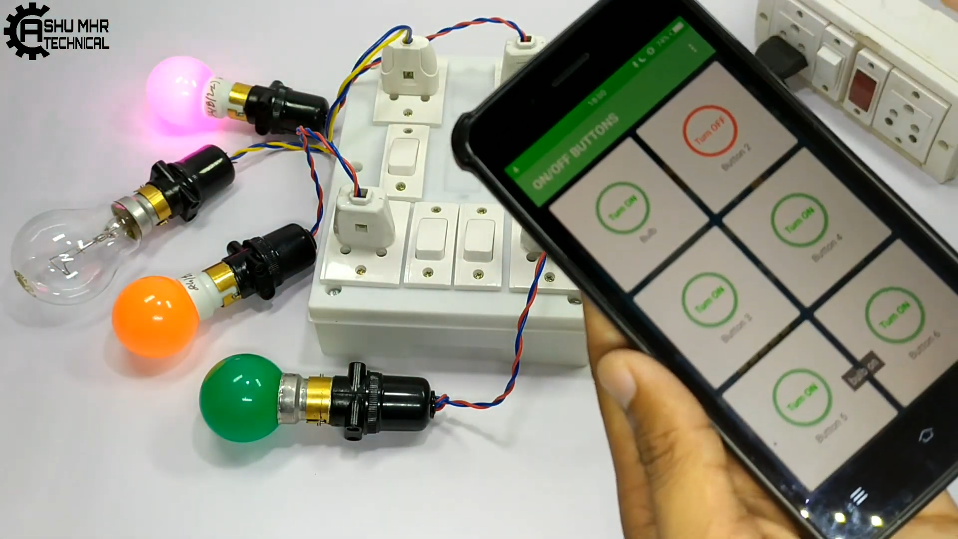
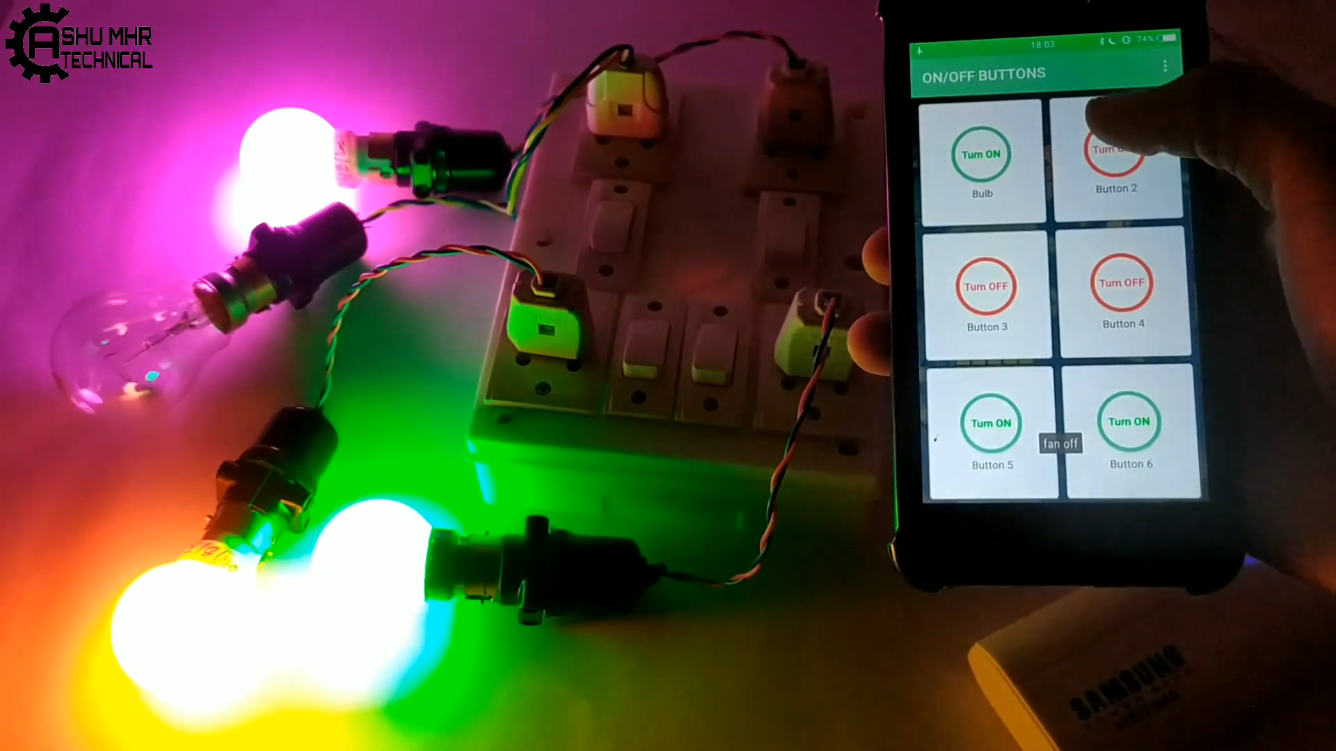
Final step:
- Power the Arduino with any adapter or power bank, also power the extension board.
- Connect the HC-05 with the Arduino Bluetooth control app and now turn on the electrical appliance with the help of the app wirelessly or even from the Physical Switch itself!
![]()
![]()
![]()
New users will also get a $30 coupon while registering at JLCPCB via this blue link.
Thank you for reading this guide, hopefully, this guide provides full steps to help you to create your own SmartExtention Board. If you have any questions please post them in the comments section below.
SMART EXTENSION BOARD
It is an Arduino based Bluetooth controlled Smart Extension Board Controlled via App or even manually by Physical switches
_4DLvW1nXnh.png?auto=compress%2Cformat&w=740&h=555&fit=max)
_zJshWDw4Vv.png?auto=compress%2Cformat&w=740&h=555&fit=max)
_lW0AbxsMdz.png?auto=compress%2Cformat&w=740&h=555&fit=max)


_1PBFefg2fC.png?auto=compress%2Cformat&w=740&h=555&fit=max)
_lhgfhaaxV1.png?auto=compress%2Cformat&w=740&h=555&fit=max)

_UjmnI8EcgJ.png?auto=compress%2Cformat&w=740&h=555&fit=max)


_5kEhtV5lQH.png?auto=compress%2Cformat&w=740&h=555&fit=max)


_4nFF5lXu7y.png?auto=compress%2Cformat&w=740&h=555&fit=max)
Discussions
Become a Hackaday.io Member
Create an account to leave a comment. Already have an account? Log In.