 Yann Guidon / YGDES
It's real !
https://www.facebook.com/photo/?fbid=10161435312547019
But I didn't make it, @Ken Boak did and this is just enough to implement a D-FlipFlop.
From the above link :
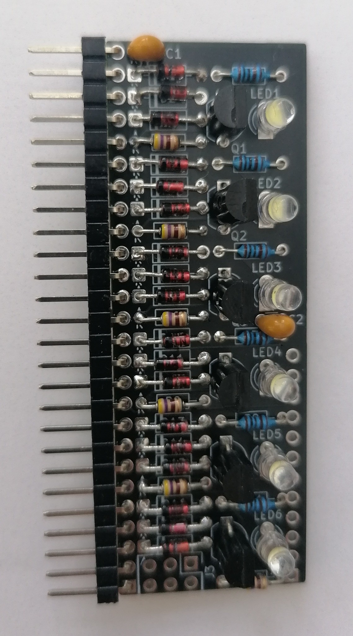
Here is the completed flipflop.
It took about an hour to build, but it was the first one, so I was learning the build sequence and I was photographing every stage for the documentation.
There are 140 soldered joints, and I guess if I make some tooling to hold the components in place I can get the build time down to about 30 minutes.
One down, ready for testing. Another 24 to go. 😉
Please note - this board was designed for the 2N3904, but I am using BC547C - that is why all the transistors are "backwwards" compared to the pcb legend.
The collector load resistor is 470R, the LED pullup resistor is 1K.
Current when working at 5V and 12.5MHz clock is estimated to be about 40mA.
I'd like to thank @Tim for the original idea of #LED Coupled Logic (LCL) / L-DTL. @matseng / Mats Engstrom for giving me the idea of the "StripChip" format, @Yann Guidon for some friendly advice and Joseph Watson his ideas on a 2-T flipflops solution - which will be my next port of call.
Thanks also to other members of the group who have offered ideas and critical thinking.
.
Good job !
Discussions
Become a Hackaday.io Member
Create an account to leave a comment. Already have an account? Log In.
very exciting stuff. this is one to watch.
Are you sure? yes | no
if only Ken published on his own project page, instead of the forgetware site that is Facebook.
Are you sure? yes | no
I have started to document here:
https://hackaday.io/project/203927-white-light-logic
Sorry for the late start - but I have been busy soldering :)
Are you sure? yes | no
@monsonite yes !
Are you sure? yes | no