 Joel Kozikowski
-
1Building the Pro Controller
The Pro Controller and its software is the heart of the system, so it is the place to start with a build. Its major materials include:
- Raspberry Pi 4
- 480 x 320 SPI LCD touchscreen
- Joystick board (available on Amazon)
- Custom Pi Hat PCB
Step 1 involves gather all of the components needed for the build. A complete bill of materials can be found here.
Also part of the bill of materials is the custom "Pro Controller Pi Hat." This custom single sided PCB can either be ordered from your favorite PCB fabrication service, or you can fab it at home using your current DIY PCB board technique. The Gerber files for this board can be found here.
Step 2 involves 3D printing the case. STL files can be found on GitHub here. I prefer to use PETG, so that is what I printed everything in. After printing, there are 8 holes on the base that need to be tapped using a 3MM tap system (two for the lid, two for the joystick board, and four for the Raspberry Pi). I prefer to to use a tap vs. attempting to have the 3D printer print the threads, as metric taps are inexpensive and easy to use on 3D printed plastics.
Step 3 involves creating a few custom cables necessary to connect all of the components together. There are two main cable harnesses used internally:
One is a simple 26 pin (2 x 13 pins) male to female IDC ribbon cable used to connect the Pi to the LCD. If you don't have the connectors to make your own ribbon cable, you can buy a pre-fabricated 40 pin ribbon cable made by UCTRONICS.
The other harness is used to connect the Pi Hat connectors to the other board. This harness is made up of four parts:
- Barrel connector for 24VDC power input
- Power to toggle switch to other switched connectors
- Switched 24VCD to CNC connector
- Switched 24VDC to Exposure table connector
The schematics for these wire harnesses can be found here.
The toggle switch harness:

24VDC input via barrel connector:
![]()
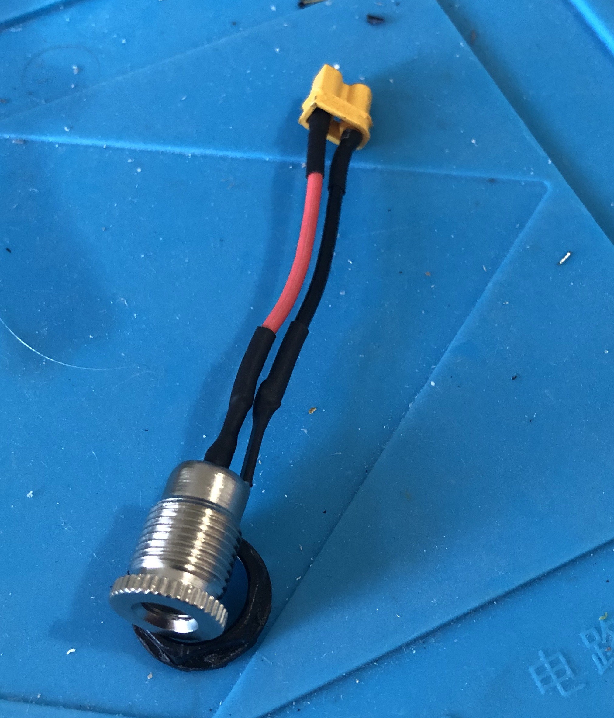
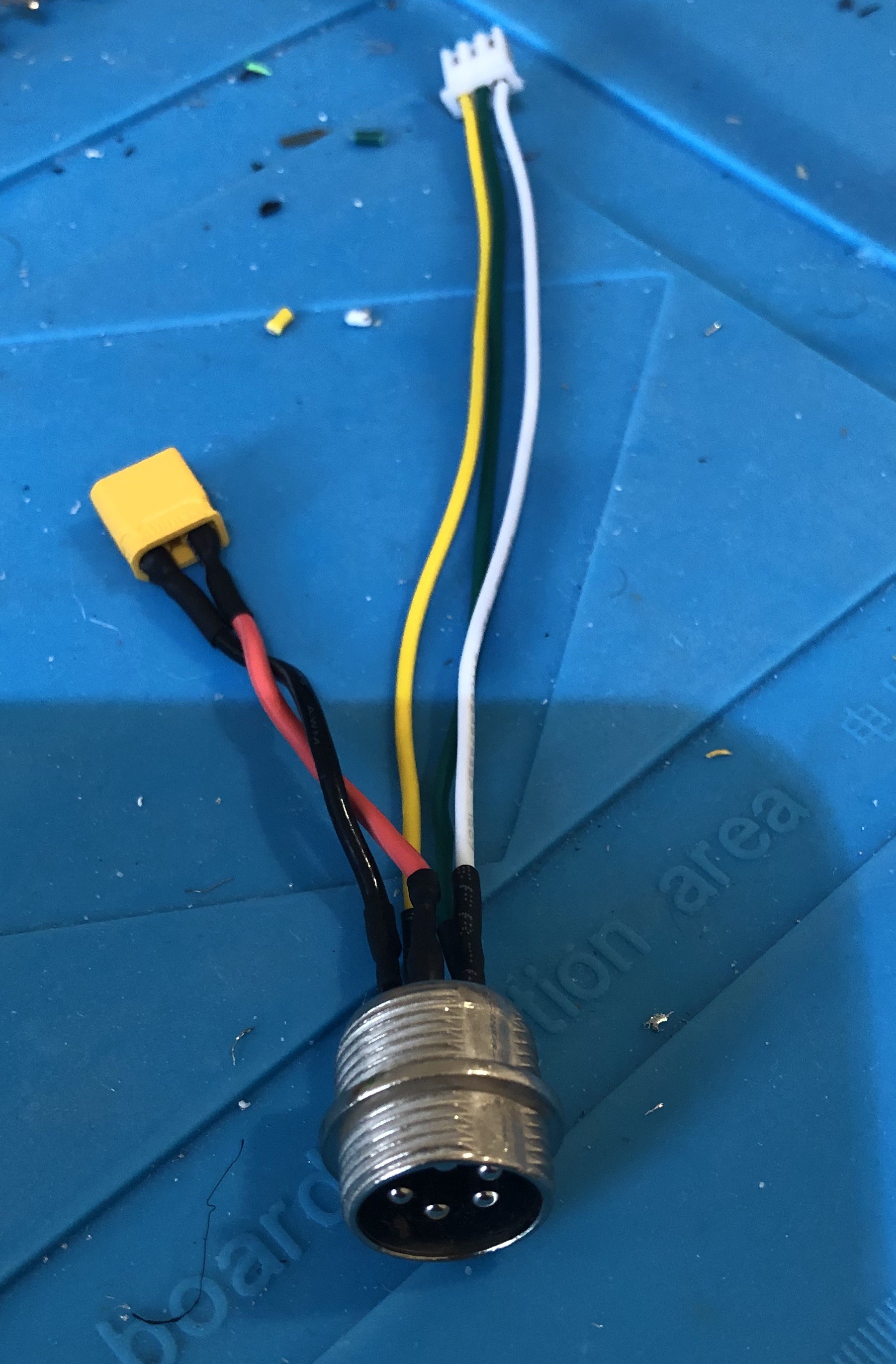
For connecting CNC machine (aviation connector for power and line controls):
![]()
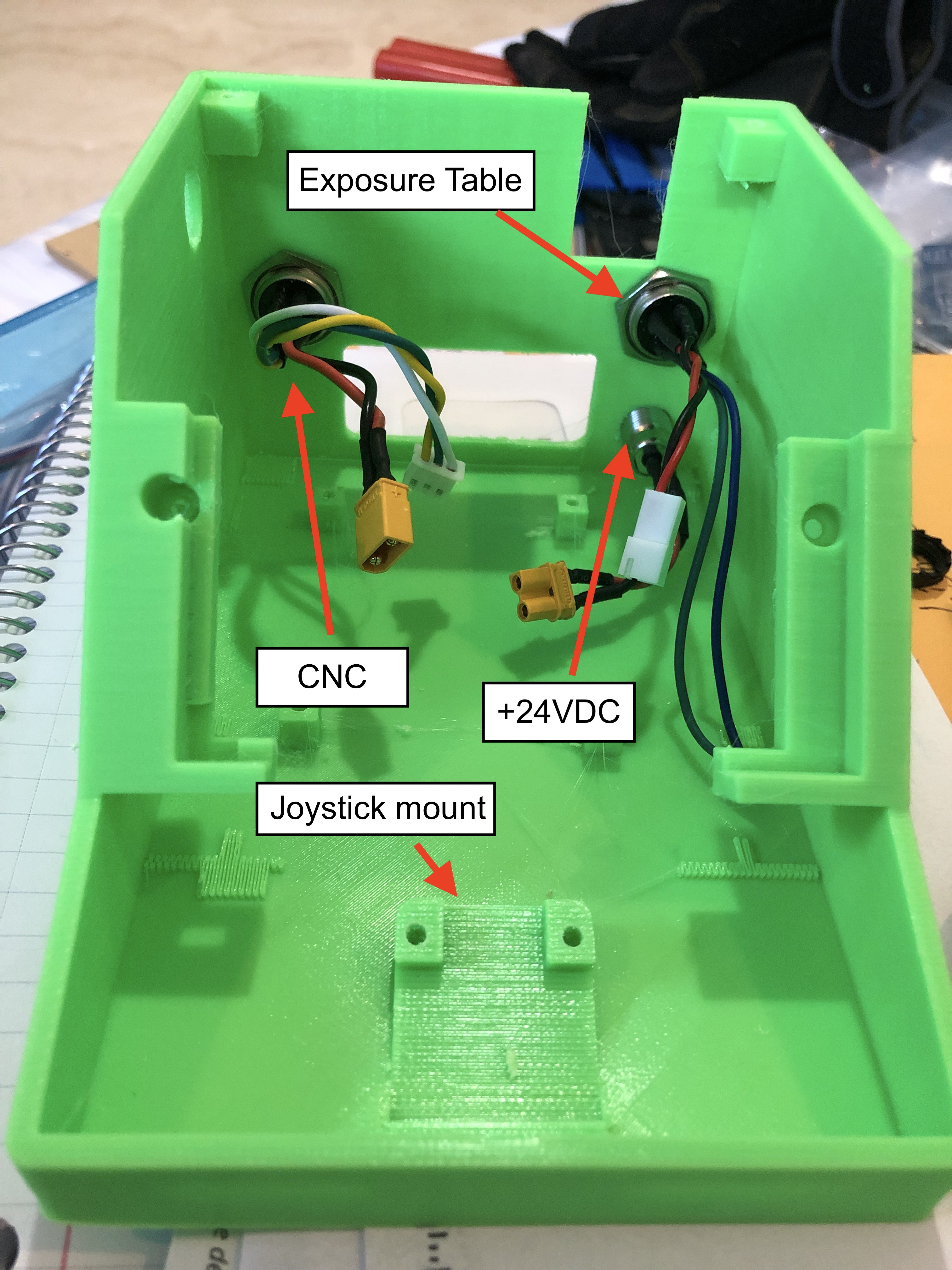
The other sections, installed in the controller base
![]()
Step 4 involves soldering the components on to the Pi Hat PCB and tuning the voltage regulator. Connect the Pi Hat to the wiring harness WITHOUT connecting the Pi Hat to the Raspberry Pi. Power the Hat with 24VDC, and then use the screw on the voltage regulator to tune it to output 5.1 VDC. Attach your voltmeter to pin 2 of the stackable header pins as the positive and pin 6 as the negative. This will make sure the voltage regulator supplies the proper voltage after passing thru the on board diode. Once the voltage regulator has been tuned, you may turn off the power and attach the Pi Hat to the Raspberry Pi
Step 5 involves installing the Pi and Hat into the case and making all of the remaining connections.
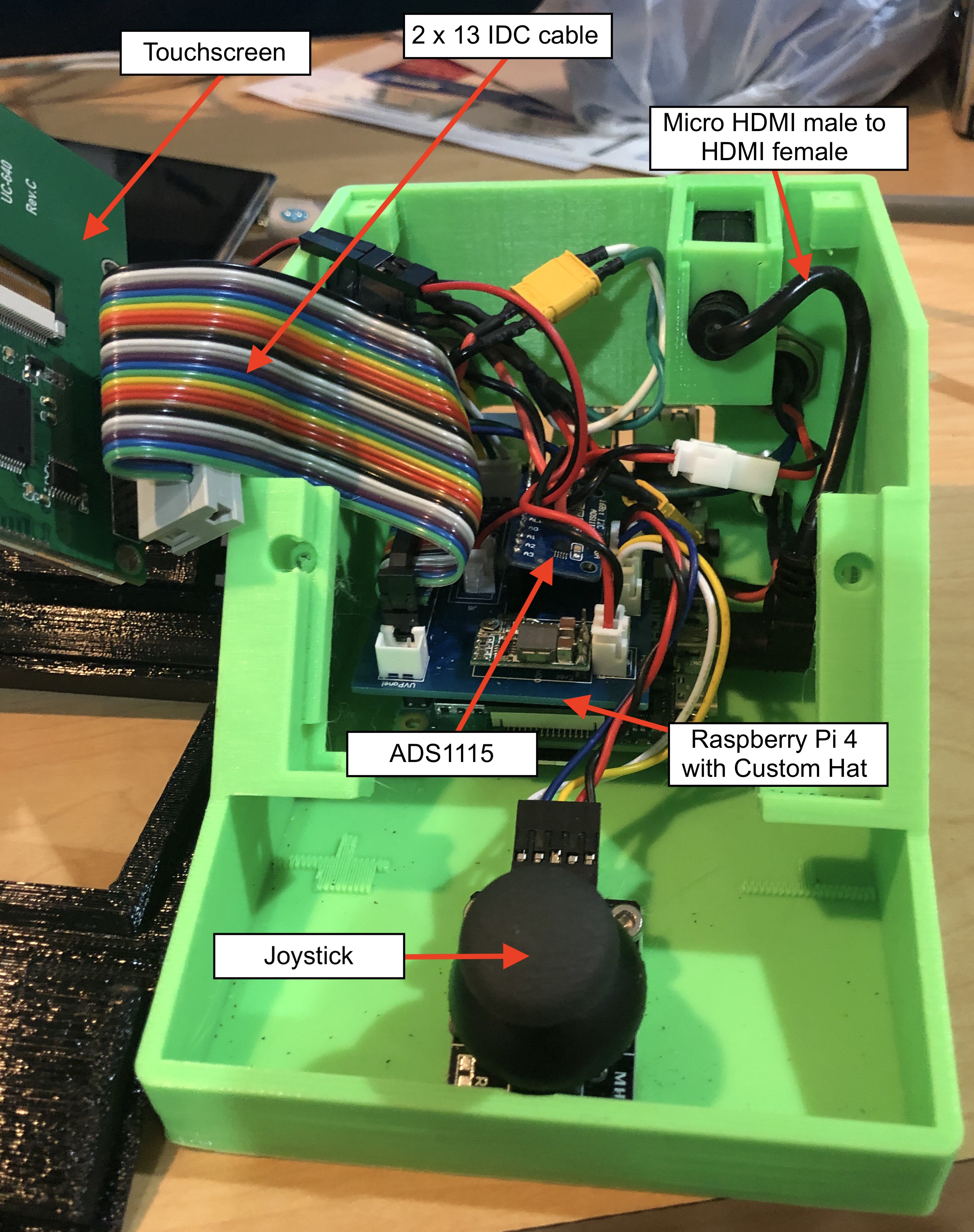
Controller base with Pi and Hat installed:
![]()
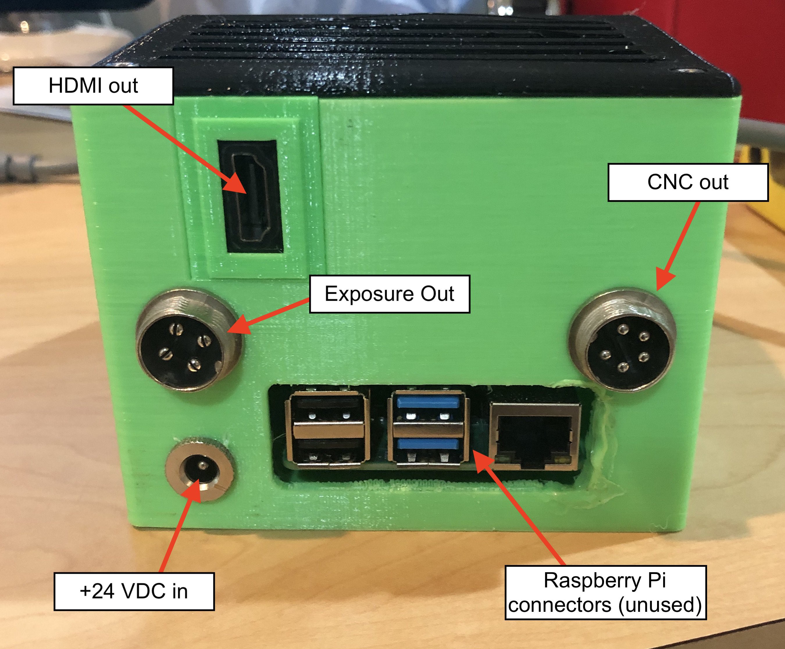
Rear view of controller:
![]()
Step 6 involves installing software and configuring the Pi. Follow the GitHub docs found here.
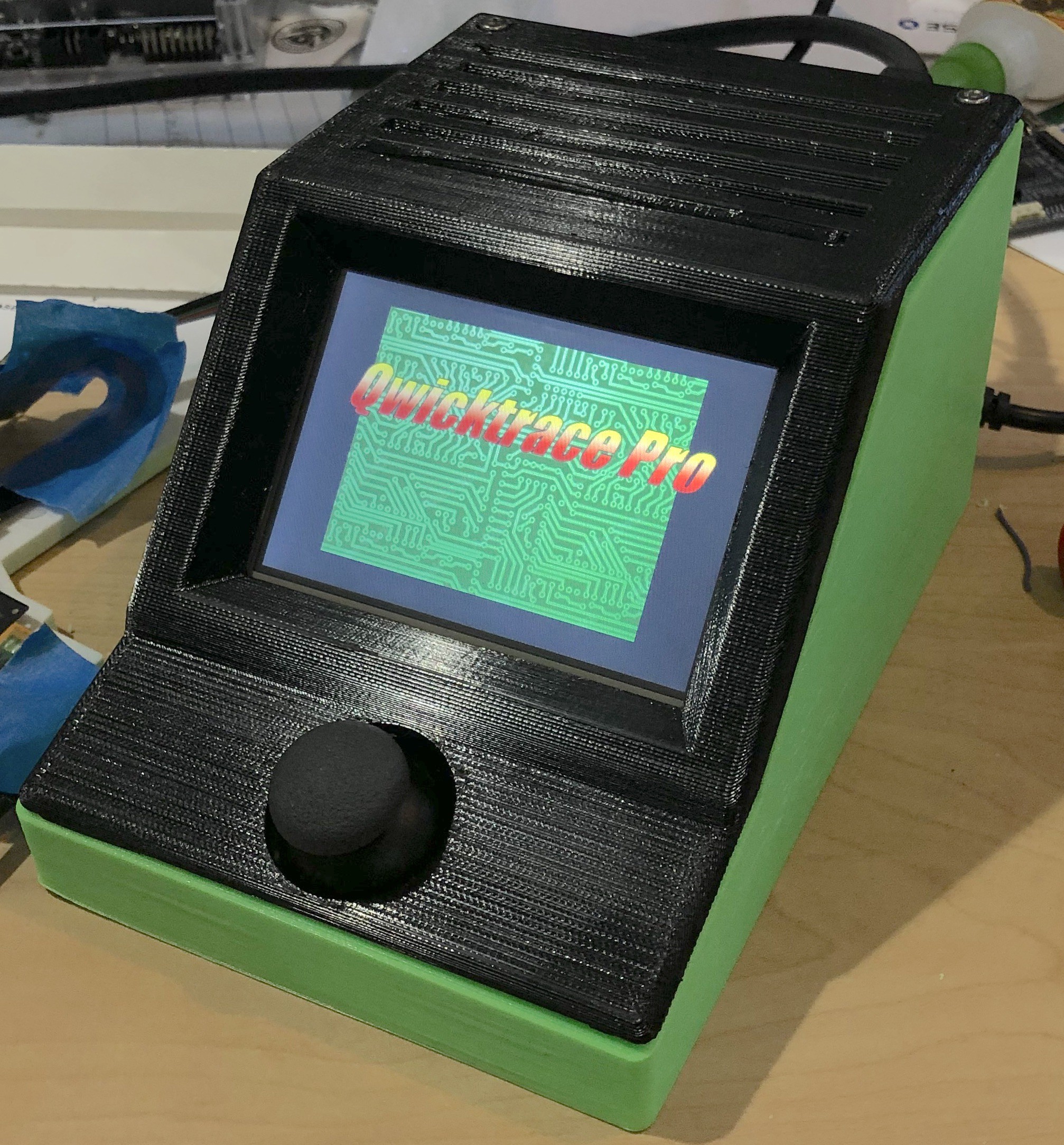
The completed controller:
![]()
-
2Building the Exposure Table
The workhorse of the QwickFab system is the exposure table used to expose photosensitive copper boards to UV light. Its major parts include:
- UV Light assembly replacement for Sparkmaker 3D MSLA printer
- 5.5 Inch replacement LCD Screen with glass for Elegoo Mars/Anycubic Photon 3D Printer
- Sharp 2k LCD MIPI to HDMI interface board
- Amber LED brake light (used as the "safe light")
- Flexible mirror sheets
- Custom PCB interface board
Step 1 involves gather all of the components needed for the build. A complete bill of materials can be found here and here. The UV Light housing can be tricky to source from non-Chinese sources. However, they can be easily found from numerous vendors on Ali Express or Bangood.
The Mars/Photon replacement screen is actually glass with a Sharp LS055R1SX04 2k LCD screen. To interface with it requires an MIPI DSI (Display Serial Interface) to HDMI adapter board. These can also be tricky to source, especially stand alone. The board is most frequently sold paired with an LCD screen, which adds about $30 to the cost. There are vendors on Ali Express or Bangood that do list the board stand alone, so if you are ordering the UV Light from one of those sites, you may also want to shop the for the HDMI adapter board there also.
Also part of the bill of materials is the custom PCB "interface board" This custom single sided PCB can either be ordered from your favorite PCB fabrication service, or you can fab it at home using your current DIY PCB board technique. The Gerber files for this board can be found here.
Step 2 involves printing the 3D parts for the build. STL files can be found here. As with the Pro Controller, I printed these parts with PETG also.
Step 3 involves creating a few custom cables necessary to connect all of the components together. There are two custom cables used:
- JST XP to USB Micro to power the HDMI board
- A long four connector cable to interface to the Pro Controller
The other cables used are pre-made: and HDMI cable, and the 5 pin ribbon cable that comes with the UV Light assembly
The JST to USB cable looks like this:
![]()
Step 4 involves building the "safe light" assembly. The Photosensitive copper boards are sensitive to ultraviolet light in the 300 to 400 nm range. The "safe light" is an high intensity amber LED brake light that emits primarily in the yellow/orange part of the spectrum, rendering its light harmless to the copper board. The safe light is used to illuminate the masked area when the end user needs to position the board or otherwise see the masked area on the LCD.
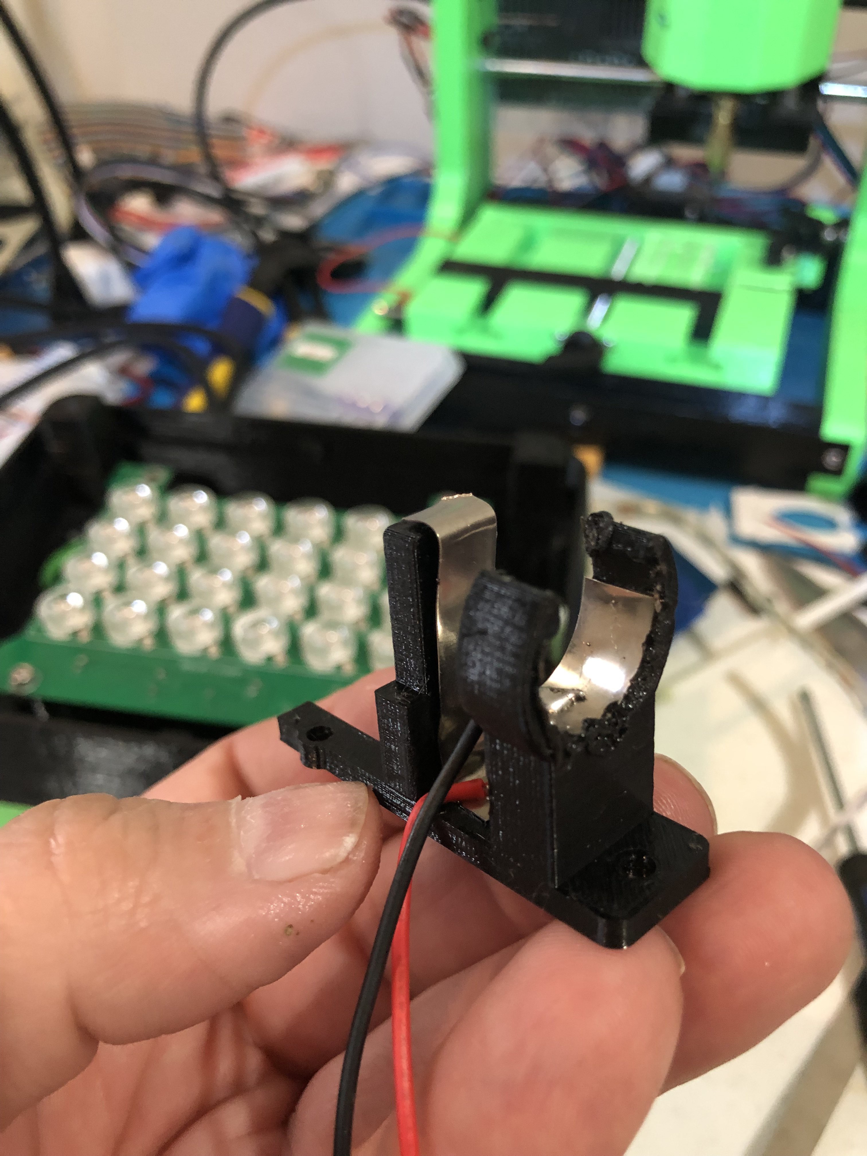
Building the safe light assembly is fairly easy to construct. It involves placing a nickel strip in the round part of the mount and soldering a black/negative wire, then placing a nickel strip at the back of the mound and soldering a red/positive wire. I simply placed the copper strip on to the mount then heated with a soldering iron to melt is slightly into the plastic to hold it in place. Crimping a JST XP connector to the other end of this wire allows the assembly to be connected to the exposure table's interface PCB.
The safe light assembly:
![]()
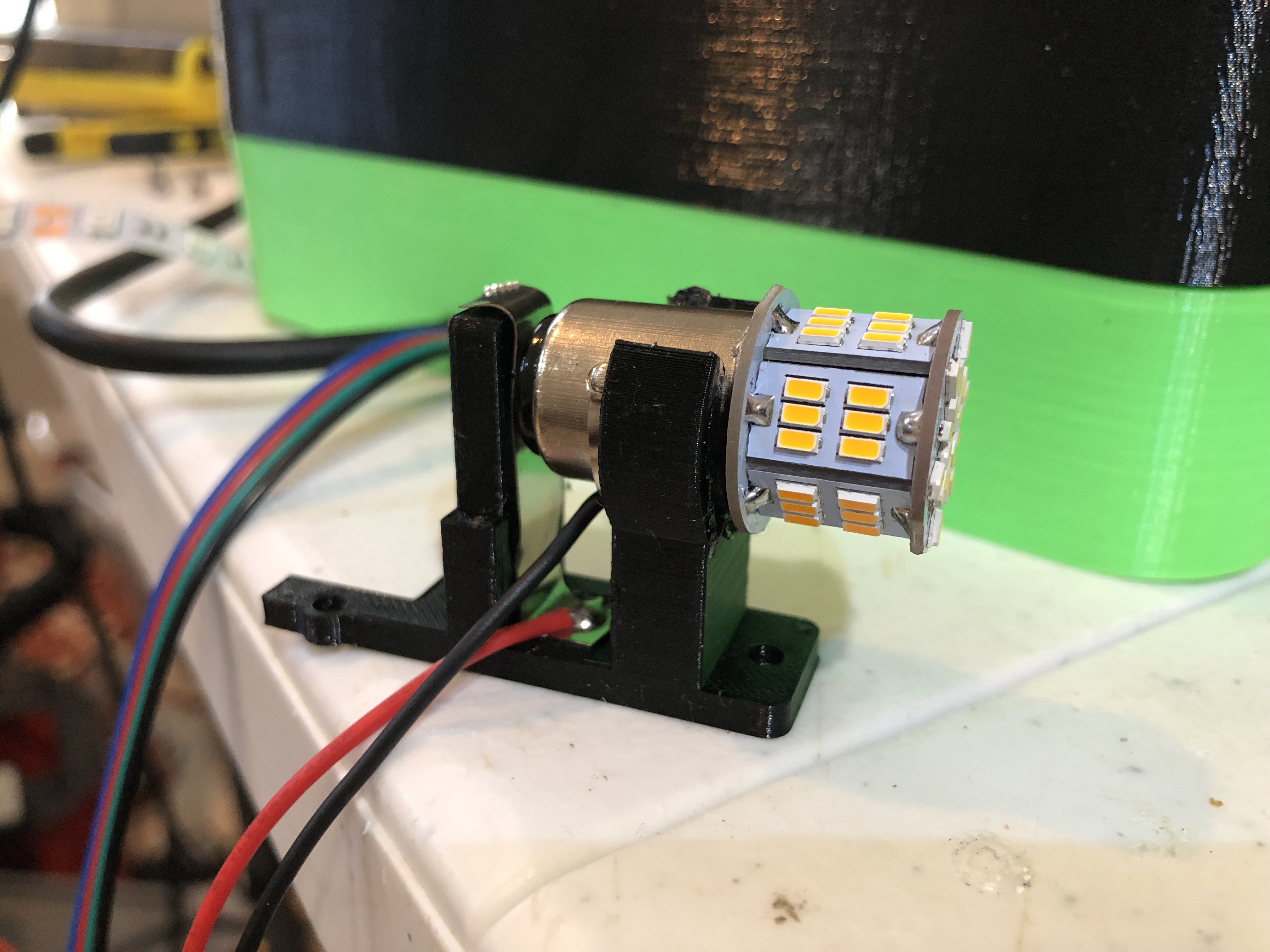
With bulb in place:
![]()
Step 5 involves attaching the "LED Layer" to the "footer", then securing the UV assembly to the LED layer. Attach the safelight assembly with an M3 screw. I then placed several strips of "flexible mirror sheets" around the area to help direct the Safelight output throughout the exposure area. The wires for the safelight, and the ribbon cable for the UV assembly are feed through the cutout down to the bottom area.
The UV assembly with safelight and mirror sheets in place:
![]()
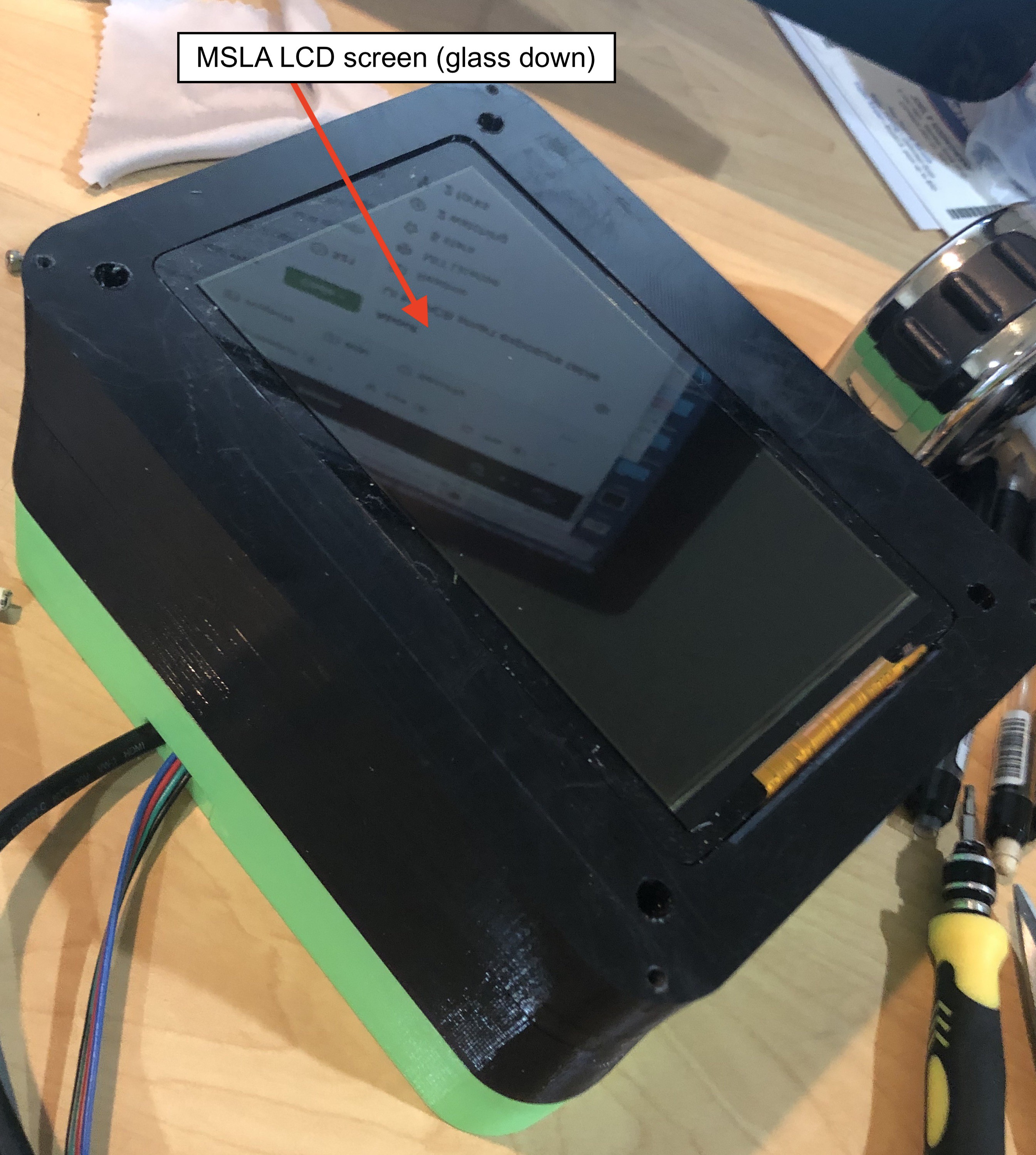
Step 6 involves assembly the LCD used to mask the PCB. It involves placing the MSLA LCD in place and feeding the cable down thru the LCD layer and into the bottom area. Discussions on version 1 of the project revealed the need to minimize the effects of parallax in the UV light to maximize focus on the PCB. To accommodate this, I placed the LCD "glass down". This means that the UV light hits the glass before it hits the masked area:
The MSLA LCD placed glass down:
![]()
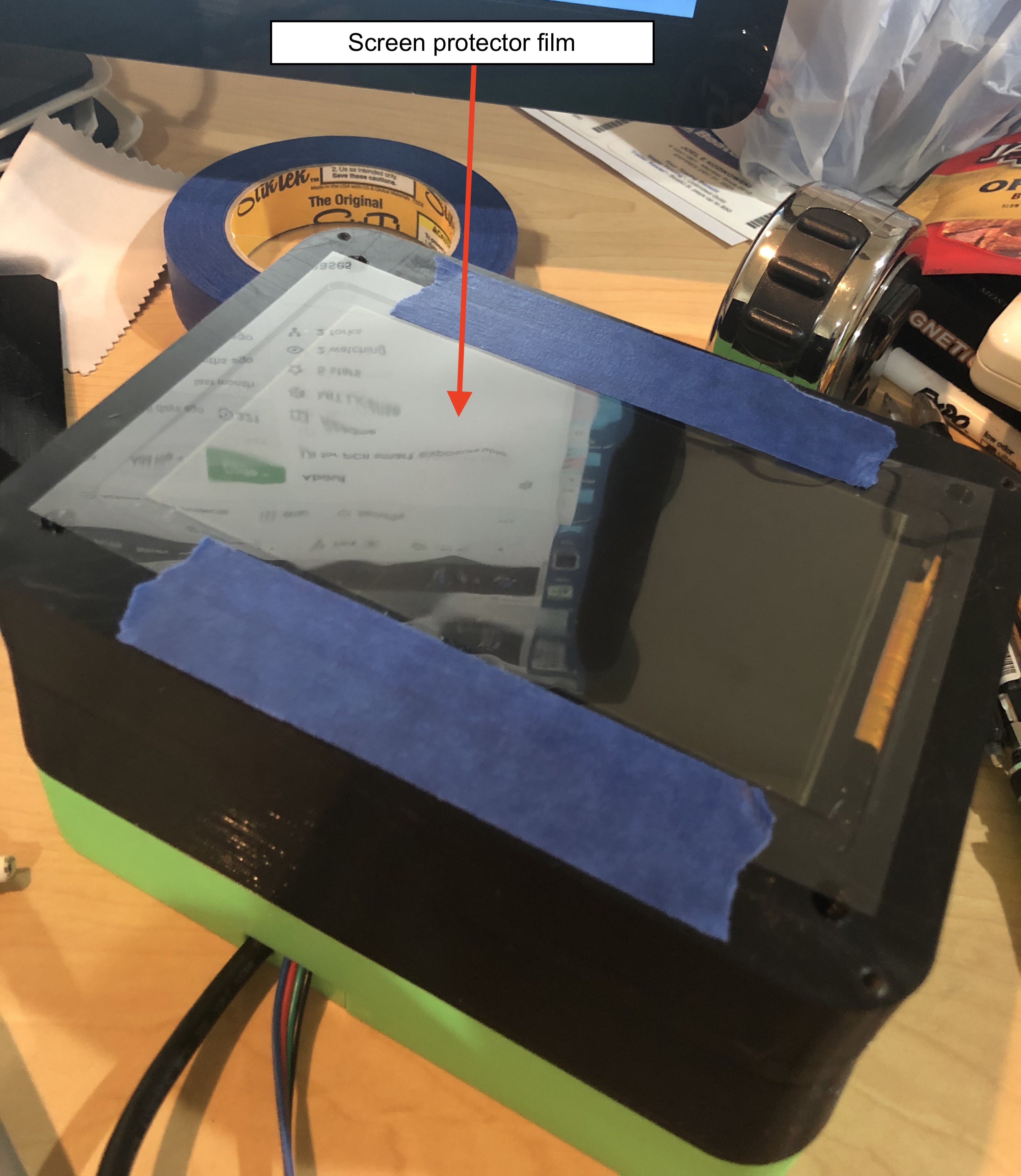
To protect the LCD screen from scratches, a thin "screen protector film" sheet is cut to size and taped down. This screen protector is much thinner than the glass, so the parallax is minimal.
LCD screen covered with "screen protector film":
![]()
Attach the "Alignment Frame" layer to the LCD layer with 3mm screws to secure the screen and protector. Once the alignment frame is in place, the table can be turned upside down and the final components can be placed in the bottom layer.
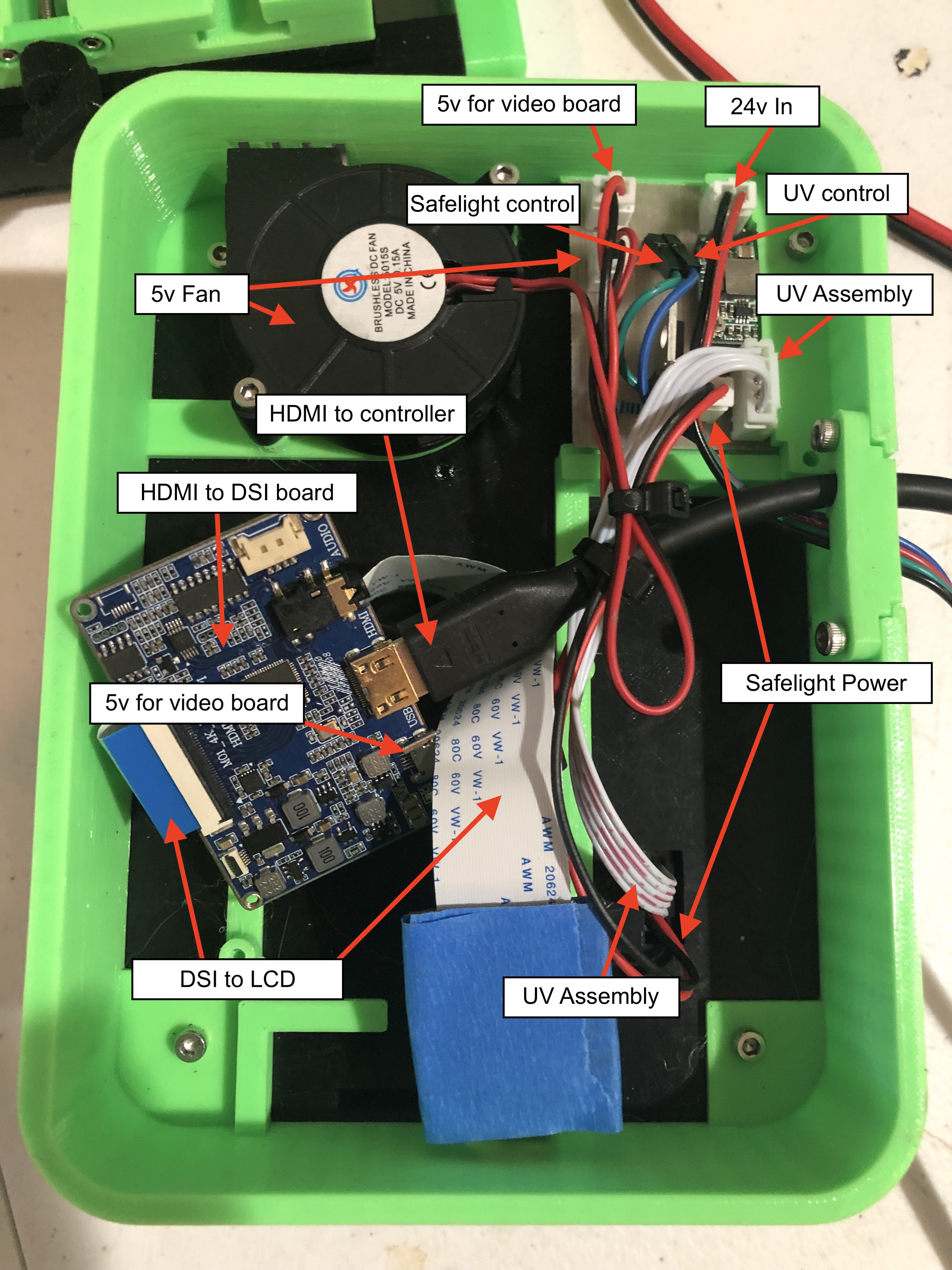
The bottom layer with custom PCB and internal parts connected:
![]()
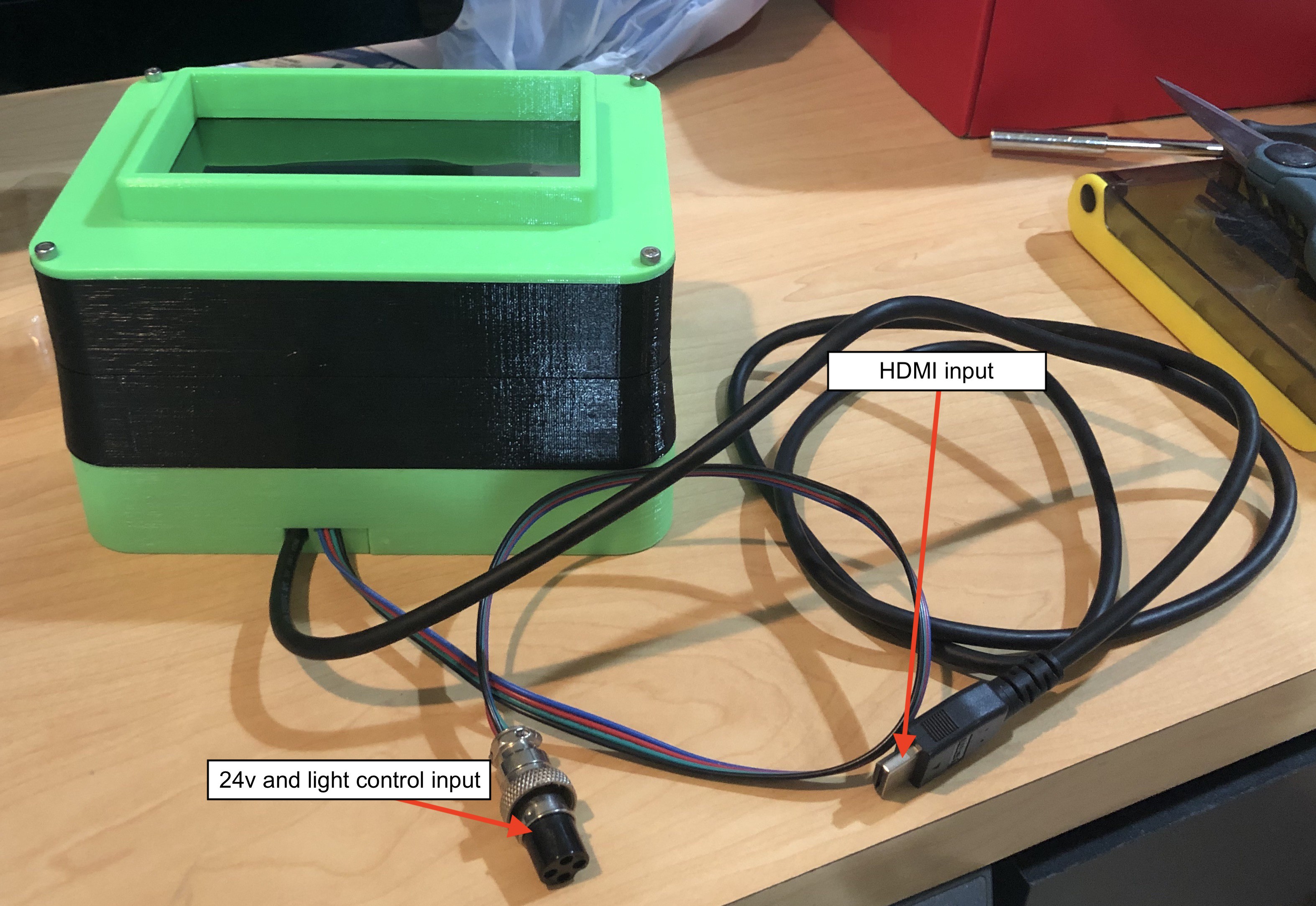
The completed exposure table:
![]()


Discussions
Become a Hackaday.io Member
Create an account to leave a comment. Already have an account? Log In.