-
1Create the base model
First step is to create the base model of the part that you want to embed the mesh into.
Here's a simple stepped ring that I created with FreeCad.

Simple stepped ring base model -
2Create the mesh holding ring
You will now need to create a small ring. This ring will be the part that the mesh is initially embedded into.

Mesh holding ring -
3Create a cutout in the base model
Now make a cutout inside of the base model which is just a little larger then the mesh holding ring. I like to start this at least 4 layers high.
I did this by creating a duplicate of the mesh holding ring in FreeCad, then slightly changing the external radius, the internal radius and the height of the part. This part was then moved inside the base model and a boolean cut was executed, resulting in a cut out inside the base model. The idea is to have the cutout be large enough to hold the mesh holding ring without excessive slop.
This picture shows a cross section of the base model with the cutout.

Cross section of the base model showing the channel created by the cutout This picture gives you an idea of how the mesh holding ring will be encapsulated in the base model.

Mesh holding ring inside the channel in the base model -
4Slice the models
Save both files as separate STL files, then slice each one and save the g-code. I used Cura for the slicing and the preview mode to figure where to modify the g-code.
In the preview mode in Cura, move up the the layers until the channel is just covered. In my case, this was at layer 12.

First layer covering the channel in the base model Make a note of the layer (12) as you will need this later. Now go down one layer and you will see the last channel layer, layer 11.

Last layer of the channel in the base model Make sure that you have saved the g-code before slicing the mesh holding ring.
Remove the base model from Cura and bring in the mesh holding ring stl. Keep the settings the same and slice the model. Record the number of layers, in this case there are 5 layers. Save the g-code.

Mesh holding ring sliced. If you are curious about the settings I used to print each one, I'll attach a Cura profile for you to peruse.
-
5Modifying the g-code
This is actually the easy part. Open the gcode for the base model in your editor. Now you will notice that the first layer in the g-code is actually Layer 0, not Layer 1, and you want to pause the printer at the last layer of the channel, which Cura preview shows as "Layer 11". If you pause at layer 11 in the g-code, you will have printed the roof of the channel and there is no way to insert the mesh holding ring. Math is pretty simple here, simply subtract 1 from the last layer of the channel as show in Cura preview.
In mine, Cura shows the last layer of the channel as "Layer 11", so the layer that I need to pause at is 11 - 1 or Layer 10.
Search for layer 10 in your editor and enter the g-code pause command. On the SnapMaker 2.0, I use the M600 command, which is actually the filament change command. Depending on your machine, you may need to use a different pause command.
Here's a snippet showing how I inserted the M600 command in the base model.
...
G0 X74.645 Y162.443
G0 X76.562 Y164.407
G0 X78.575 Y166.275
G0 X80.677 Y168.039
G0 X82.865 Y169.696
G0 X85.133 Y171.243
G0 X87.476 Y172.674
G0 X89.886 Y173.987
G0 X92.36 Y175.177
G0 X94.889 Y176.244
G0 X97.467 Y177.183
G0 X100.091 Y177.993
G0 X102.752 Y178.669
G0 X104.93 Y179.109
G0 X110.874 Y180.056
;TIME_ELAPSED:508.371818

;PAUSE FOR ADDING MESH
M600

;LAYER:10
;TYPE:WALL-INNER
;MESH:base model.stl
G1 F3600 E624.1746
G1 F4800 X113.624 Y180.193 E624.28449
G1 X116.376 Y180.193 E624.39433
G1 X119.126 Y180.056 E624.50423
G1 X121.865 Y179.782 E624.61409
G1 X124.587 Y179.371 E624.72396
G1 X127.285 Y178.826 E624.83382
G1 X129.953 Y178.147 E624.9437
G1 X132.584 Y177.335 E625.0536
G1 X135.17 Y176.393 E625.16344
G1 X137.707 Y175.324 E625.27332
G1 X140.187 Y174.13 E625.38318
G1 X142.605 Y172.814 E625.49306
G1 X144.954 Y171.378 E625.60294
G1 X147.229 Y169.827 E625.71283
...
For the mesh holding ring, I had a total of 5 layers. You want to have the pause at least 2 layers from the top, so I modified the g-code to pause at layer 2 (remember to subtract 1 from the Cura preview). This will do 2 things. First, it will make certain that enough PLA is pushed through and over the top of the mesh during printing. Second, it will offset the layers so that you have enough layers on the bottom to fit reliably in the channel.
-
6Embed the mesh
Clean you print bed and start printing the mesh holding ring. While it is printing, cut a square piece of the mesh about 1 inch larger then the diameter of the mesh holding ring. This extra will allow you to tape the mesh to the print bed to prevent it from moving during the embedding.
When the print pauses, place the mesh over the print and tape it to the bed, making sure there are no wrinkles or stretching of the mesh. I use blue printers tape because it leaves virtually no residue, is easy to remove and I have several rolls of it. Make sure you tape all 4 sides to prevent movement.
When the placement looks good, continue the print. The print head will likely impact into the nylon mesh, but that doesn't cause any issues, at least it doesn't for me. This also assures that the PLA will be inject through and around the mesh fibers securing it to the print.
Here's a time lapse video starting just after the print was paused. It shows me laying down the mesh, taping it to the bed and adjusting it with another piece of tape to the bottom to remove a wrinkle. I'm not an expert in videography, so you may need to slow it to 1/4 speed for "precise" viewing.
-
7Trim the excess mesh
One reason why I use a 2 step print process is that at this point the mesh is firmly embedded, but there is no way to remove all the little sticky out parts of the mesh, and I don't like to have a "stickery" feeling to the outside of the print. It also lacks visual appeal. By embedding this part into the main body, both issues disappear.
Here's the embedded mesh just after printing. It's important to let it cool before removing it from the bed, otherwise the print may warp, and the mesh could move slightly causing the weave to be "weird".

Mesh firmly embedded in the mesh holding ring 
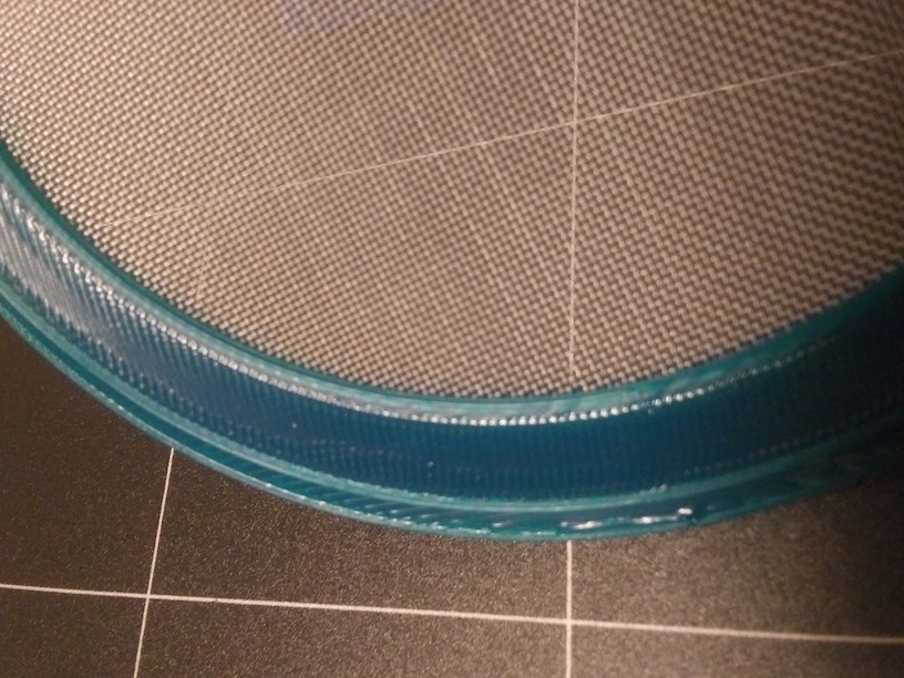
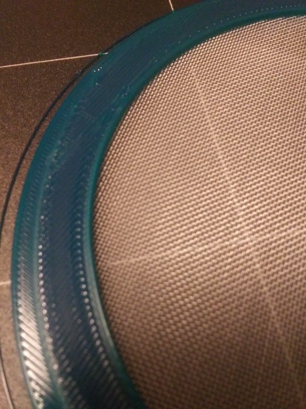
Closeup of the mesh now embedded, notice how the weave is consistent, there are no wrinkles and the print is very tight 
The mesh holding ring after printing but prior to trimming 
The mesh holding ring after trimming excess mesh It isn't necessary to get off all the excess mesh, but you don't want a huge amount still on the print.
-
8Print the base model
Clean our build plate then begin the print of the base model. I won't bore you with the starting the print, etc. Instead I will jump to the point where the printer pauses.
First a closeup of the model when M600 is encountered in the g-code. It's easy to see the channel here. The inside lip will add more support to the mesh when the print resumes.

Main body print after the M600 pause is executed Now it's time to insert the mesh holding ring. Gently lay the mesh holding ring into the channel with the smoothest side (bottom of the print) down. It may look like its setting a little high but that's normal as the print head should press it down.

Mesh holding ring laid into the channel in the main body Resume printing. In my model, the inner lip of the main body will be printed first (just how the slicer works). This first print will stabilize the mesh holding ring so that no slippage occurs.

Inner perimeter of the inside lip prints, joining the mesh with the main body and adding stability 
Overhead shot of the inner perimeter of the inside lip printing More shots of the print in progress
![]()
![]()
And the print is complete! Allow to cool and remove.

The print has completed -
9Conclusions
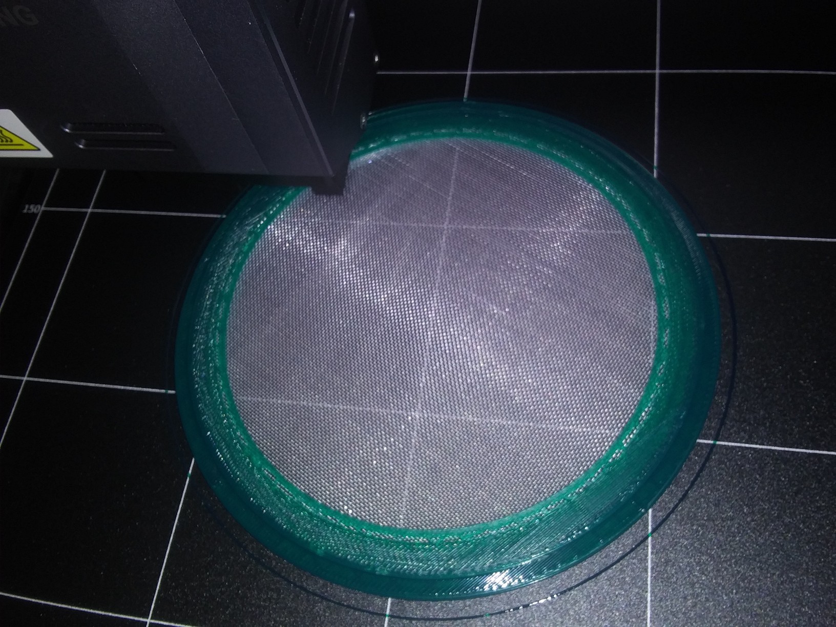
Now that the print has been completed the mesh is totally embedded and ready for use.
It is as strong as if it had been injected molded into the plastic.
Using this method, annealing doesn't result in the mesh deforming or become detached from the PLA.
As there are no top or side gaps, particle containment is not an issue.
This same process will work for other shapes too.
I haven't tested it with other types of filaments or mesh types (steel, brass, etc), but it should work for those too. Be aware that mesh types close to or exceeding the hardness of the nozzle may damage the nozzle or other parts of the machine.
Experiment and have fun!
Here are some closeups of the result. Apologies for the quality.
![]()
![]()
-
10Mesh availability
Nylon mesh of the appropriate size is difficult to find in small quantities. I had to order 114 square foot on a 6'X19' roll from the manufacturer as a minimum.
As a result, I have a large quantity of excess of size 40 nylon mesh if anyone is interested. It goes for $10 for per six square feet .
Contact me for more details.
Embedding a mesh into 3D print
Easy method of embedding a mesh into a 3D print.


Discussions
Become a Hackaday.io Member
Create an account to leave a comment. Already have an account? Log In.
Size 40 nylon mesh @ $10/six square feet = just 3 μ$/hole - practically free!
(or maybe I should go to sleep...)
Are you sure? yes | no
I think your calculations are a little off. Did you remember to include the Monofilament Nylon 6 fiber 42 threads per inch and 400 micron hole opening with 45% open area in your calculations?
Turns out I ordered the wrong size of mesh, so I've got a whole lot of 400 micron (40 mesh) left over. Discounted just for your comment to $1 per square foot. or $100 for the entire roll.
:)
Are you sure? yes | no
Oh I didn't remember anything of what I never knew :}
My lazy try at discovering how screens are spec'd came up short and confused between linear & area dimensions and apparently some amount of industry standard nonstandard approximation. "% open area" sounds like the parameter that would have made sense.
Hmm... things to do with 40 mesh screen...
Are you sure? yes | no