-
Cold start timing test
11/29/2021 at 00:26 • 0 commentsI made a cold start test connecting the GPS module to the computer using the onboard USB connector. The u-center software immediately recognizes the module and starts to display the GPS data.
In this test the antenna doesn't have a full view of the sky because it is positioned on the window sill and the wall of the house is blocking the South portion of the sky. This is clearly visible from the Satellite Position View in the u-center map, only the upper half of the map shows the visible satellites. Despite the non-optimal position, 30 seconds for the cold start is pretty good.
The design of the board can be improved a lot, I made some mistakes calculating the RF trace impedence and some other mistakes caused by my little experience in PCB design. U-blox did a great job with this module that seems to be very tolerant to noob mistakes.
The test was made using this active antenna.
-
Second reflow attempt
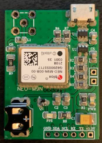
11/28/2021 at 00:32 • 0 commentsThe second reflow attempt is a success. One of the key points to take into consideration when applying the solder paste is to make sure that the stencil adheres perfectly to the surface of the pcb. Apply the right amount of paste to cover all the pads by spreading it with a sufficient pressure by holding the squeegee with an angle of about 60 degrees to the stencil. Too much pressure can cause "bleeding" of the solder paste between the stencil and the PCB.
![]()
Some of the pads, especially the ones of the GPS module, are shorted or "bridged" by the solder paste but it is fine. Once the hot plate starts to heat the board reaching the reflow temperature, the paste will be "attracted" by the pads and the solder mask ensures the separations.
-
First soldering attempt
11/21/2021 at 03:20 • 0 commentsThe GPS module is a 24 pin LCC (Leadless Chip Carrier) package which is almost impossible to solder using a conventional iron. I wanted to make experience with reflow soldering so I bought the Kester Lead Free No-Clean Solder Paste and this heating hot plate.
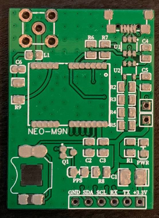
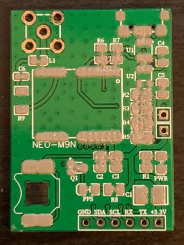
Using the stencil I made all the possible mistakes applying the solder paste, the result was this ugly looking thing:
![]()
![]()
![]()
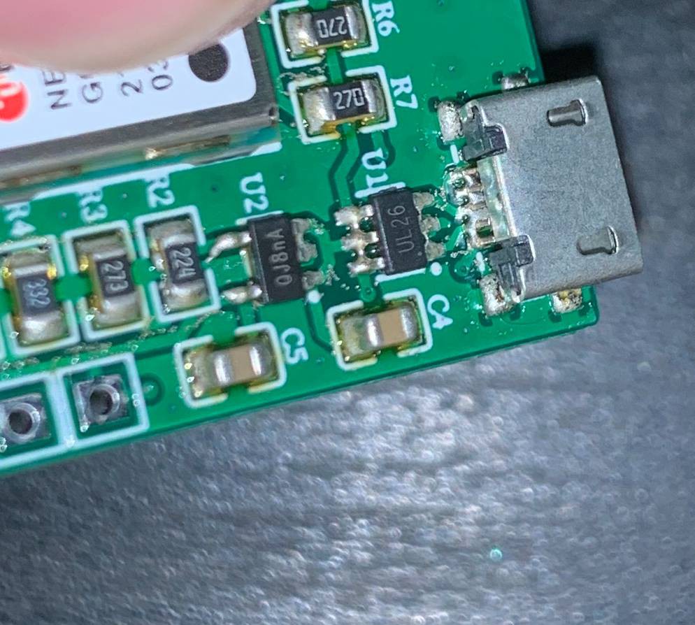
Even though I was sceptical, all the passive components are soldered pretty well but the pins of the micro USB connector and the UL26 ESD protection chip are all shorted. I tried to fix them using the solder but eventually I decided to remove the GPS module by heating the board and make a second attempt paying attention to apply the solder paste correctly.
Ublox NEO-M9N GPS breakout board
Custom PCB created to test the u-blox NEO M9N GPS module