-
Reverse engineering - first steps
01/02/2022 at 01:37 • 0 commentsAt this point it was late November.
The obvious thing to do, given the device was working, and just displaying (and outputting on the serial port) the incorrect time, was look at using it as an accurate 1-PPS source and connecting it to a Raspberry Pi zero as a network time server, although the same server would still rely on Internet NTP to get started. The GPstar also had a number of other outputs, including the disciplined 10MHz reference and programmable frequency outputs. So still a useful lab tool.
However, the star attraction is the time and date displayed on the front.
So the other choice, was to try and reverse engineer the device and see if it was possible to fix the display in the firmware. That would preserve the glorious retro display! At the same time, it would presumably be possible to fix the serial output and send the time to a Raspberry Pi and have a time server that continues even if the Internet drops out. Or even, embed a Pi or other microcontroller inside and hack a wifi upgrade...
In a previous log (https://hackaday.io/project/182779-late-90s-gps-time-unit-repair-1024-week-bug-fix/log/200777-most-recent-learnings-on-the-architecture) I described an overview of what I learned surveying the circuit and inferred from disassembly (to be documented later)
As mentioned, there is an 80C188 and an 27C010 128kByte EPROM. So after swotting up about the 80C188, which is close enough to an 8086/88 which I had programmer in assembler, lets say a very long time ago, I pulled the EPROM with a view to dumping its content.
First problem: I have a Willem EPROM programmer/reader, but it is parallel port based, and last time I checked required a Windows/XP computer to drive... the only new enough but old enough functioning PC with a parallel port in my collection runs Debian, and my efforts to locate Linux software turn up not much, although I'm still searching. I really didn't want another rabbit hole dealing with that, so while I'm waiting to borrow a TL866 from a friend I rigged up my Raspberry Pi 400 and used that to read it.
Luckily, the 27C010 is 3v3 tolerant, so I was able to direct connect it to the Raspberry PI GPIO.
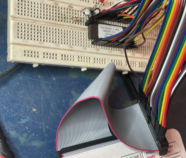
Secondly, the 27C010 has a lot of pins, so I got lucky and managed to squeeze it in...
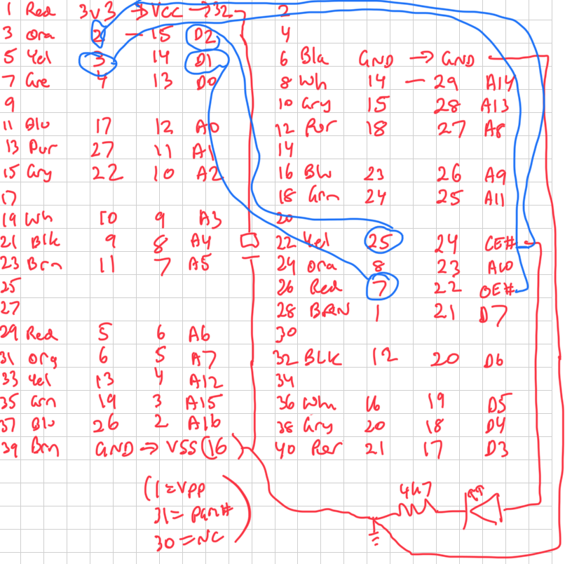
Along the way I was getting a lot of corrupt reads until I realised that a couple of the PI pins have resistor pull-ups meaning they had to be used as output only, once I swap the jumpers around I was able to get consistently the same captures.
The LED & resistor is on the CS line, the capacitors across Vcc and GND. They might be overkill, I was using them when debugging the corrupted read before I re-read the Pi bus spec and realised that pins 3 & 5 had resistive pull-ups and I switched them to drive CE/ and OE/
This is the pinout I used:
The code will shortly be on GitHub, it is a simple Python program I borrowed from somewhere else and modified.
As an experiment, I first wrote a program using bash script and it turned out it took over 10 hours to dump the entire chip :-) I then discovered I had the wires backward in the code and had to use another program to reverse the bit order. The python program however takes a couple of minutes... much more effective!
-
The 1024 week GPS bug
01/02/2022 at 01:19 • 1 commentTo recap: the week after I fixed the power supply, was when I fired the GPstar 365 back up. This happened to be 19th November 2021, the purpose of stating that idle fact will become apparent shortly.
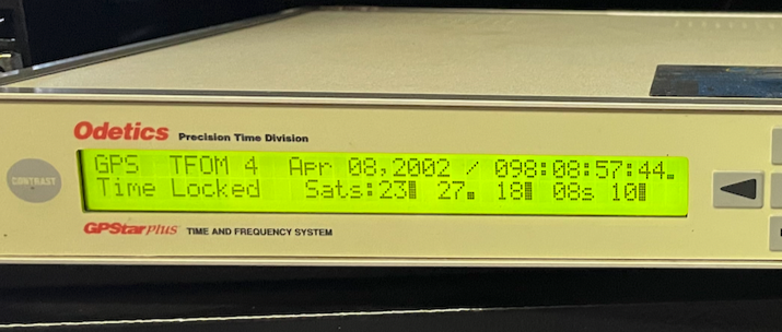
After hanging the antenna out and waiting a half or or so for the system to stabilise, I discovered to my disappointment that it was not properly tracking the time - at all - and on further investigation, the time was correct and the date was wrong. After some brief online searching, I realised the system appeared to be subject to the GPS 1024-week bug. You can read some more about it here: https://en.wikipedia.org/wiki/GPS_week_number_rollover
The 1024-week bug is caused by the use of a 1024 bit counter to represent weeks of operation, which rolls over, you guessed it, every 1024 weeks. This corresponds to exactly 19.69 years, or 19 years and 36 weeks if we ignore leap years. This counter is integral to the wider GPS system and not specific to any particular device model.
The time shown on my GPstar was 8th April, 2002, 08:57AM.
The current local time was 22 November 2021, 19:27
So, 10.5 hours from UTC (here in South Australia) and 19 years, 8 months, 14 days out - or close enough to 19.69 years incorrect!
![]()
-
Power hijinx
12/01/2021 at 11:25 • 0 commentsSo 5 weeks ago I rediscovered this GPstar Plus 365 while having a clearout, and decided to power it up and hopefully (finally, 10+ years down the track) put it to use.
So I put it on the bench, power cable and antenna connected, hit the power, and.... nothing.
Not to be discouraged after a couple of goes I disassembled the enclosure for a closer look.
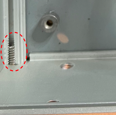
---------- more ----------The casing itself is interesting - there are four machine screws at each end, if you undo one end then the side slides out sideways. In fact if you are not careful all the panels slide out and you have things falling everywhere... kind of ingenious and fiddly at the same time. You can see the thread cavities as the are 1/4 open, where you slide in the panels...
Anyway with voltmeter in tow it didn't take long to discover the PSU had no output.
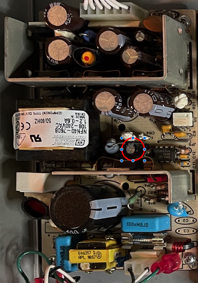
Circled is the capacitor I eventually worked out had failed.
To the left of that is a resistor which has over 300VDC across it. Given this was an open mains switch mode power supply I was already suspicious, so making sure I used a meter on 1000V mode with one hand in my pocket and well insulated leads when probing...
To the right of the circled capacitor is the control chip, a UC3842AN. It turns out this was a widely used part at the time.
To cut a long story short, it didn't take too much googling to discover that there seem to be a number of forums or blogs in Eastern Europe for some reason where people have fun reverse engineering and discussing such power supplies, and along with the data sheet and a couple of hours tracing the circuit I worked out this design was fairly close to that provided as a reference by the manufacturer.
Across the week I traced out enough of the circuit to understand how it worked.
One interesting thing is that the control chip won't actually start working as a frequency controller for the SMPS until the input voltage for it reaches around some DC voltage (I think in the order of 15, I don't have the data sheet open while writing this), in this case it was only coming up to about 8. To a very very rough approximation of reality* this is to do with ensuring the chip can properly drive the FET and the main transformer: to bootstrap power on, there is a capacitor which first charges up past that voltage and then feeds the chip with a zener regulator, this is in parallel with the actual voltage generated through a rectifier on a secondary tap of the transformer once things are up and running, also clamped by same Zener. However that secondary tap is not running at power on, and when the capacitor fails, it won't provide the necessary bootstrap voltage, and the chip won't start switching the FET. This can be confusing when first drawing up the circuit.
This all happens in the section in the middle between the two heatsinks - the upper in particular marks an isolation boundary between mains-hot and the output stage, provided by the transformer, and also an optocoupler providing feedback.
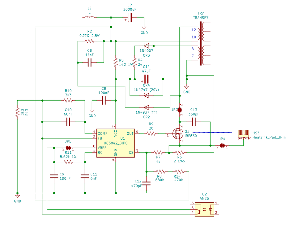
I redrew my sketch in Kicad to make it easier to read.
(Picture -
There you go, the zener CR4 is clamping the bootstrap Vcc to 20V.
The voltage between L? and R5 is full rectified mains, so watch out!
The failed capacitor was C14, 47 uF.
The 14 ohm resistor was looking decidedly brown from heat, I guess it is to limit inrush to charging the capacitor and when it is failed the voltage drop and power is larger.
A week later, when I desoldered C14 (more about that in a later post) it gave me an excuse to finally buy an ESR meter with which I confirmed that it was indeed failed, with a very high internal resistance and low capacitance.
(*I do understand all the math and circuit theory, I'm just not spending the bandwidth documenting it, but by all means feel free to post in the comments for the benefit of other readers :-) :-) )
-
Most recent learnings on the architecture
11/29/2021 at 23:14 • 0 commentsBecause I already started this project, the logs will be a mix of stuff already done and new work. I'll try and make that clear.
This post is a summary of a bunch of work over the past month: this thing is turtles all the way down.
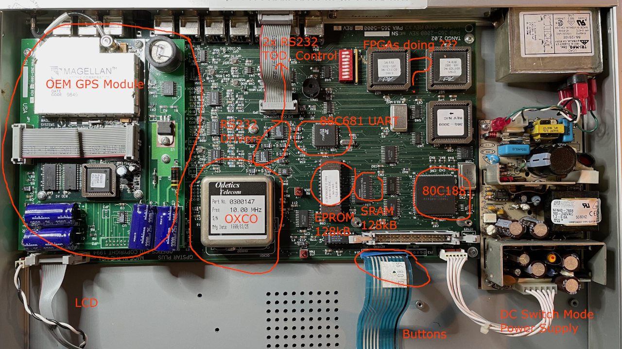
On the inside is a Magellan OEM GPS module, which is providing the time and synchronisation to the rest of the box... I'm not even going to attempt to touch the module, it is enough work to understand the microcontroller.The module which, if I am understanding the firmware correctly, provides a 1-PPS and a time feed to the microprocessor, which although is doing a bunch more complicate stuff, ultimately then updates the LCD display and outputs the time on an RS-232 port. And I'm guessing the same 1-PPS from the module is actually split 3 ways, to the microcontroller as discussed, to a BNC on the back of the box, and also it disciplines the 10MHz OXCO which then is then provides a 1kHz interrupt feed to the microcontroller...
You can see the thing was built in the late 90's. Does this mean we call this "classic" now?
The microcontroller is an 80C188, which is like a simplified 8086 with an 8-bit data bus, and includes an timer and interrupt controller and chip select logic and other features to reduce the part count when designing embedded systems, like a half way house to a modern microcontroller, the main thing is the ROM and RAM and UART are still on the outside. The other good (or bad) thing is it is quite "simple" to disassemble once you get your head around segmented addressing, which back in the day is what you needed to know to make .COM programs for DOS, so that had me really stretching the memory for a while getting back to speed.
The firmware is in a 27C010 128 kByte EPROM, which after I dumped it discovered had quite a bit of spare space. The 88C681 UART is a family commonly used in the time period which means it hopefully won't be too hard to work out where it is used, although in the end I probably won't need to understand it because I found the functions that send entire strings to it.
This thing also outputs real old-school RS-232 with -/+ 12V logic... two ports, one with a time of day stream once a second, where the first character is a '!' that is specified to always appear within 10mS of the GPS time - it is kind of interesting how this is achieved once you look at the firmware. The other is a control port with a kind of but not really GPIB like text protocol, where every message has an XOR checksum at the end.
I found the manuals for all this online quite easily, there are two, one for the GPstar 365 and one for the communication protocol. It turns out re-reading them made it easier to understand the firmware disassembly, which make sense and I probably wasted a good number of hours before I went back and did that again...
The 3 big chips to the upper right are some kind of FPGA I don't know what they do probably control timing to make sure the 1-PPS and the other signals out the back all work to spec (various programmable divisions of the 10MHz synchronised frequency reference)
![]()
Near the RS232 drivers is a 3-port jack labelled "Aux rs232" - I'm still hoping this might be a mirror of the control port which will make it very easy to mount a Pi or ESP8266 inside without feeding cables back in - when I had this running, there was no signal other than a flat -12V on what I infer to be the tx line, but I hadn't read the manual yet so I think I need to configure the control from the front panel first (I hope). I was wondering if it might be a debug serial port like we see in all newer gear but there are only two driver chips.
Just to the right of the 80C188 is a 93C46 eeprom, there is also a DS temperature sensor, so this system is talking i2c & maybe 1-wire as well.
-
Finding ways to dump an EPROM without a programmer handy
11/29/2021 at 08:18 • 0 commentsPerhaps I should do a separate project with just the EPROM dumper. I used a Raspberry PI 400 to read the content of the 27C010 128kByte EPROM. Only components was a capacitor across the power and a LED & resistor on OE# to check it was working...
-
Prelude
11/28/2021 at 10:32 • 0 commentsNow is 2021-11-28. At the time I created this Hackaday page:
- I have spent about 8 hours over 4 weeks dismantling, waiting for parts, repairing, breaking, and repairing again the switch mode PSU. At that point was when I discovered the device has the 1024 week bug
- I then in the past week spent about 24 hours over a week building an EPROM dumper using just a Raspberry Pi, jumper wires and breadboard, acquainting myself with Ghidra, and reverse engineering enough of the 80C188 code to get to a point where, when I next spend time, I can intercept a call to sprintf() and patch in the time difference to have the correct display come up, also, similarly, report the correct time on the Time of Day serial port of the device. To do this I need to buy, borrow or build an EPROM programmer, or maybe an EPROM emulator to start with :-) That won't fix the GPS location though, it is looking like the GPS position also comes from the internal engine and I can't patch the time in that ...
- then I need to take the 1-PPS output and loop it back into the case so I can hide a raspberry Pi inside it
- also a lot of learning I need to document here
- this is looking like a long term project now so I am going to aim to limit the time to 2-ish hours a week, first catching up the documentation, then, after an EPROM programmer arrives, patching. So sometime in 2022, if I don't stop before then... I have other more important projects, and of course work and family so this needs to take a back seat. It is easy to get sucked into a rabbit hole...
Late 90s GPS time unit repair & 1024-week bug fix
Repairing and fixing the firmware of a late 90s GPS time receiver
 pastcompute