This is the third version of the board because in V2 there was a problem with the AEM10300 status pin ST_STO that became low unexpectedly. In this design I added a simple voltage supervisor that monitors the storage (Lithium Ion Capacitor) voltage and when the voltage drops below 2.5V it's output pin (STAT) goes low. Then the buck boost converter is disabled and the Lithium Ion Capacitor is protected from draining below 2.5V. The RC filter delays the buck boost converter enable pin so that the host processor can be warned for an impending shut down.
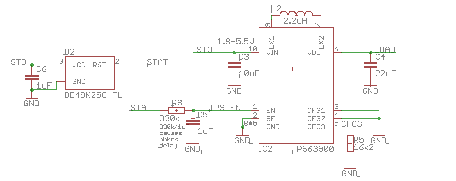
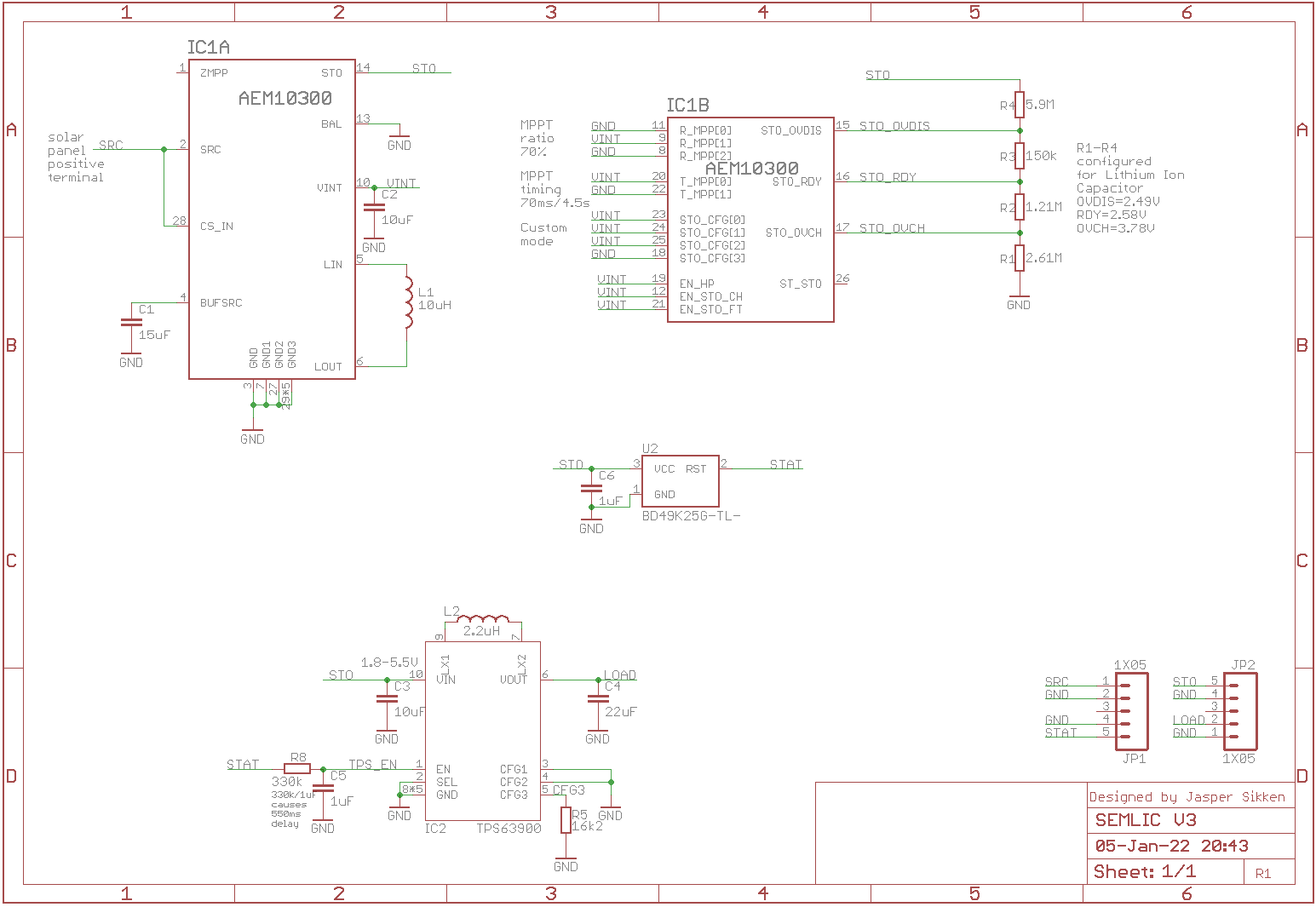
I removed the two resistor connected to TPS63900 CFG1 and CFG2 pins, because I think most user don't want to switch dynamically between two buck booster output voltage levels. Now the full schematic looks like this.
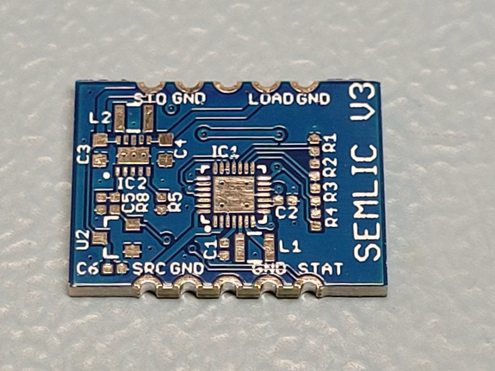
I have ordered 10 PCBs from Elecrow and the bare board looks like this.
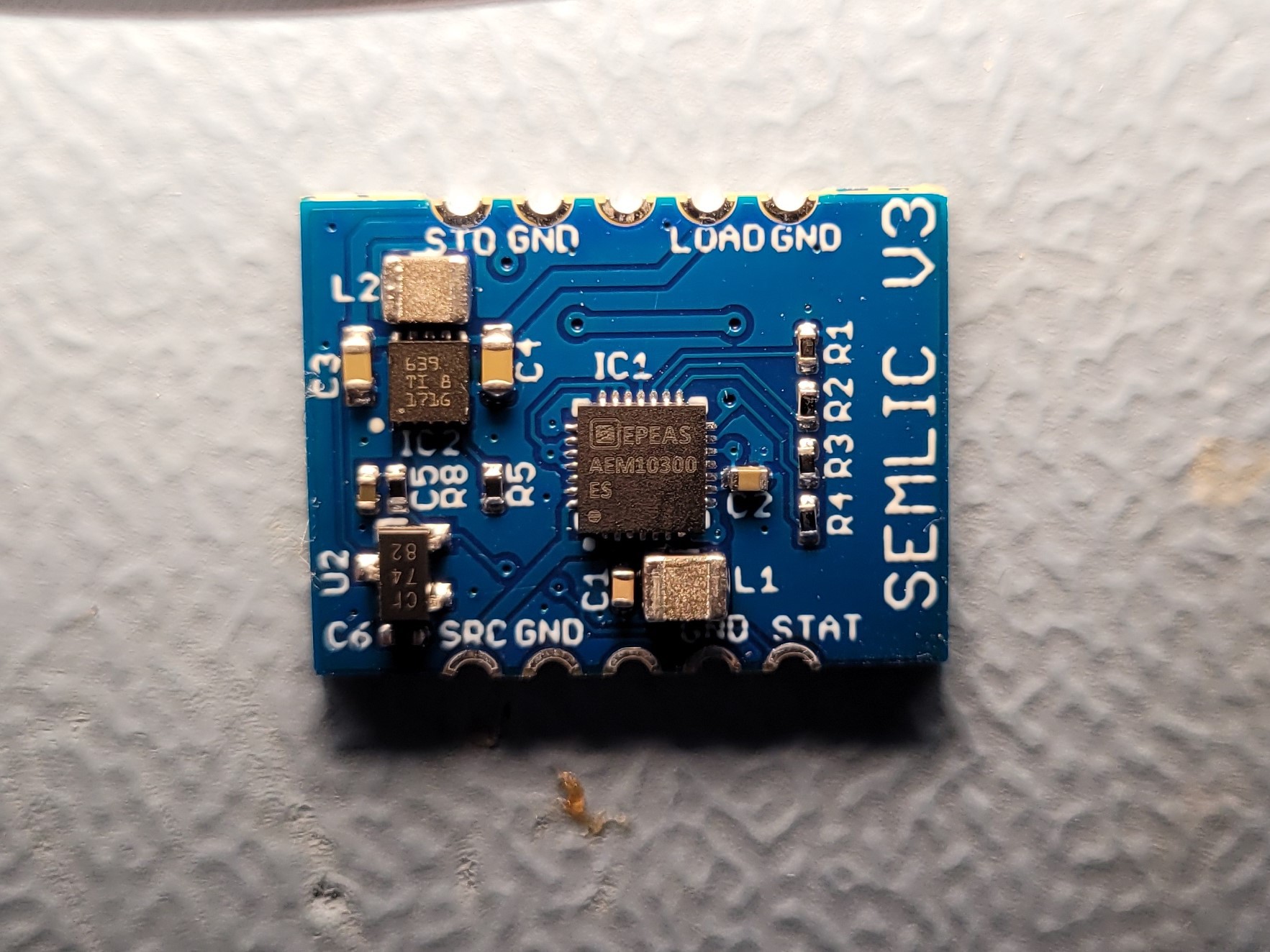
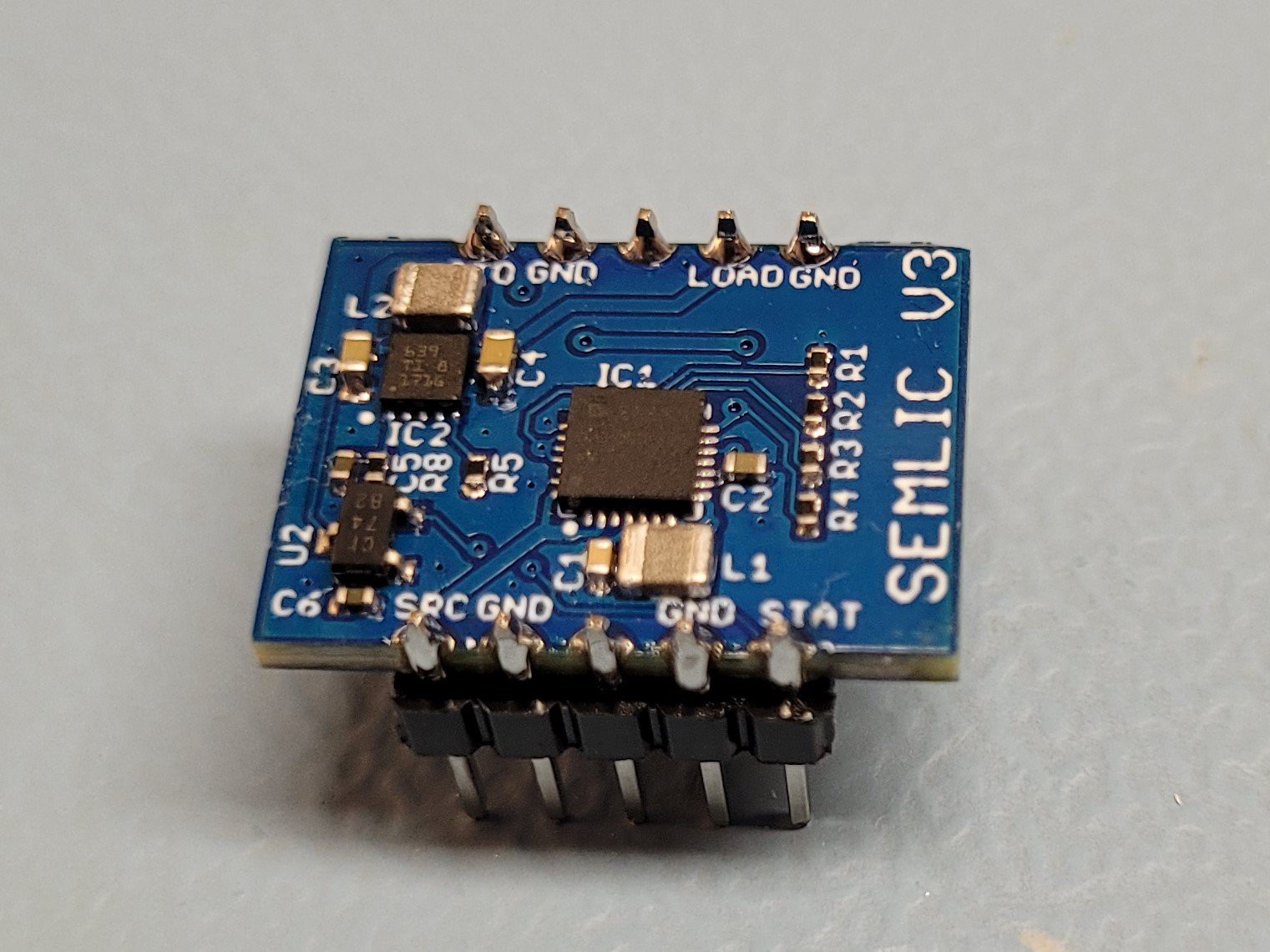
I assembled one board
Soldered it onto headers
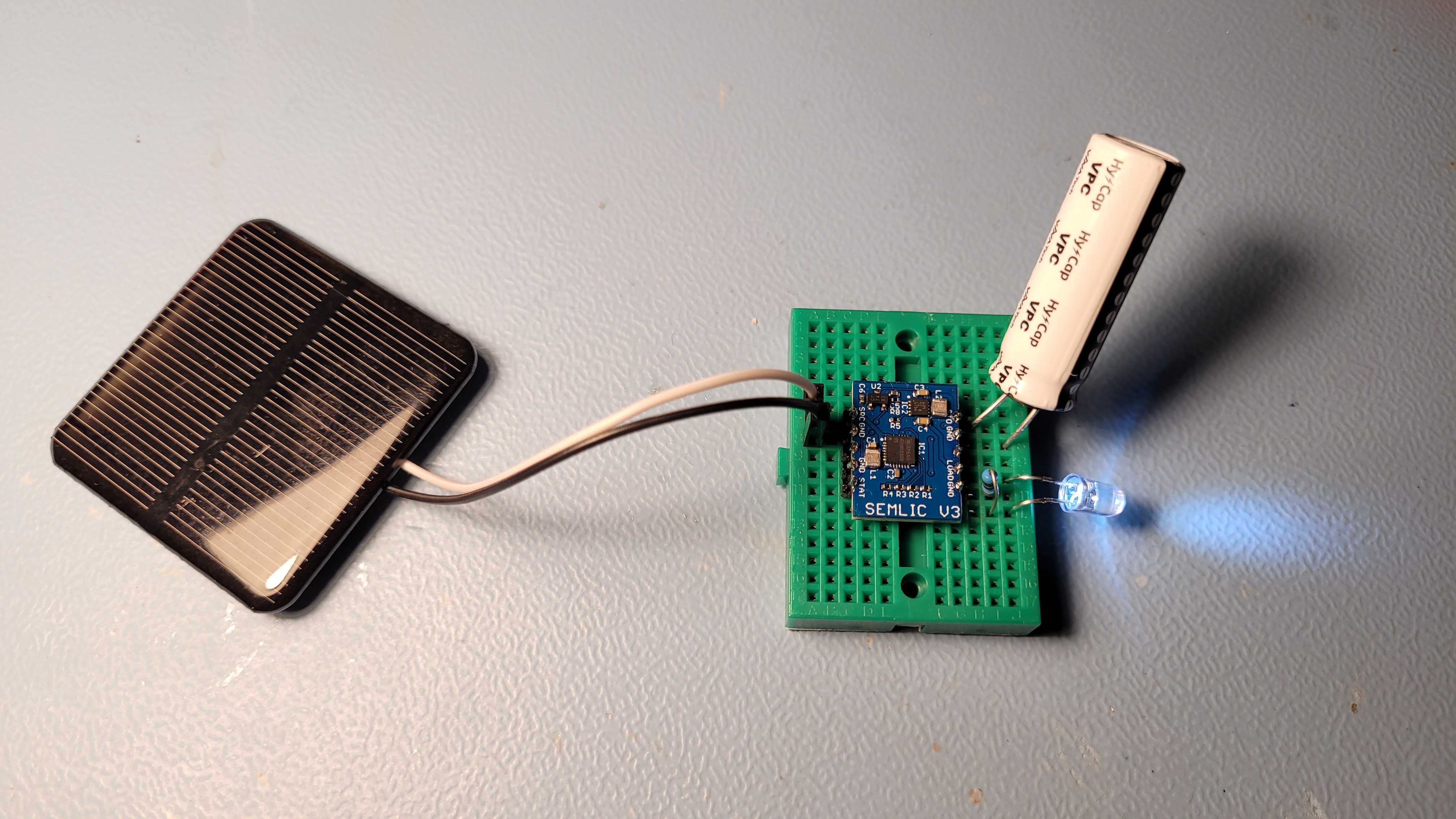
Plugged in a 2V/160mA solar panel and a Vinatech 250F 3.8V Lithium Ion Capacitor and a LED.
And I have performed design verification
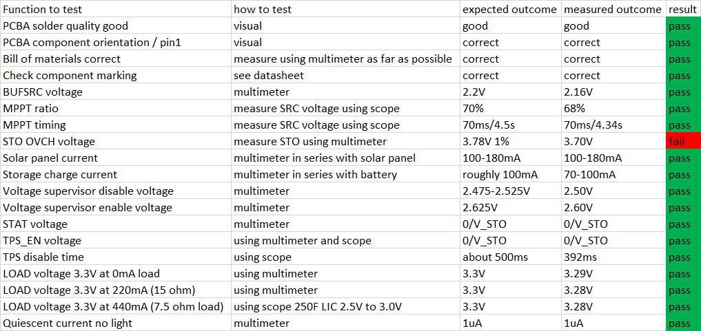
and it almost works as expected. Wow, I am almost ready to start production. I heard from E-peas by mid of February AEM10300 should get qualified so that sounds good. Next step is to build a field test device and to monitor its voltage over a few weeks. Hopefully no new issues show up. In the mean time I can make final touches to the PCB and order the first fully assembled batch of 50 or 100.
 Jasper Sikken
Discussions
Become a Hackaday.io Member
Create an account to leave a comment. Already have an account? Log In.
hi Rafael, follow me on Twitter. I try to think of you when I have few boards assembled
Are you sure? yes | no
Are you sure? yes | no
Hi Rafael, FYI, I have just assembled the first board and it seems to work. I wiill continue the testing coming week.
Are you sure? yes | no