-
Finishing it off
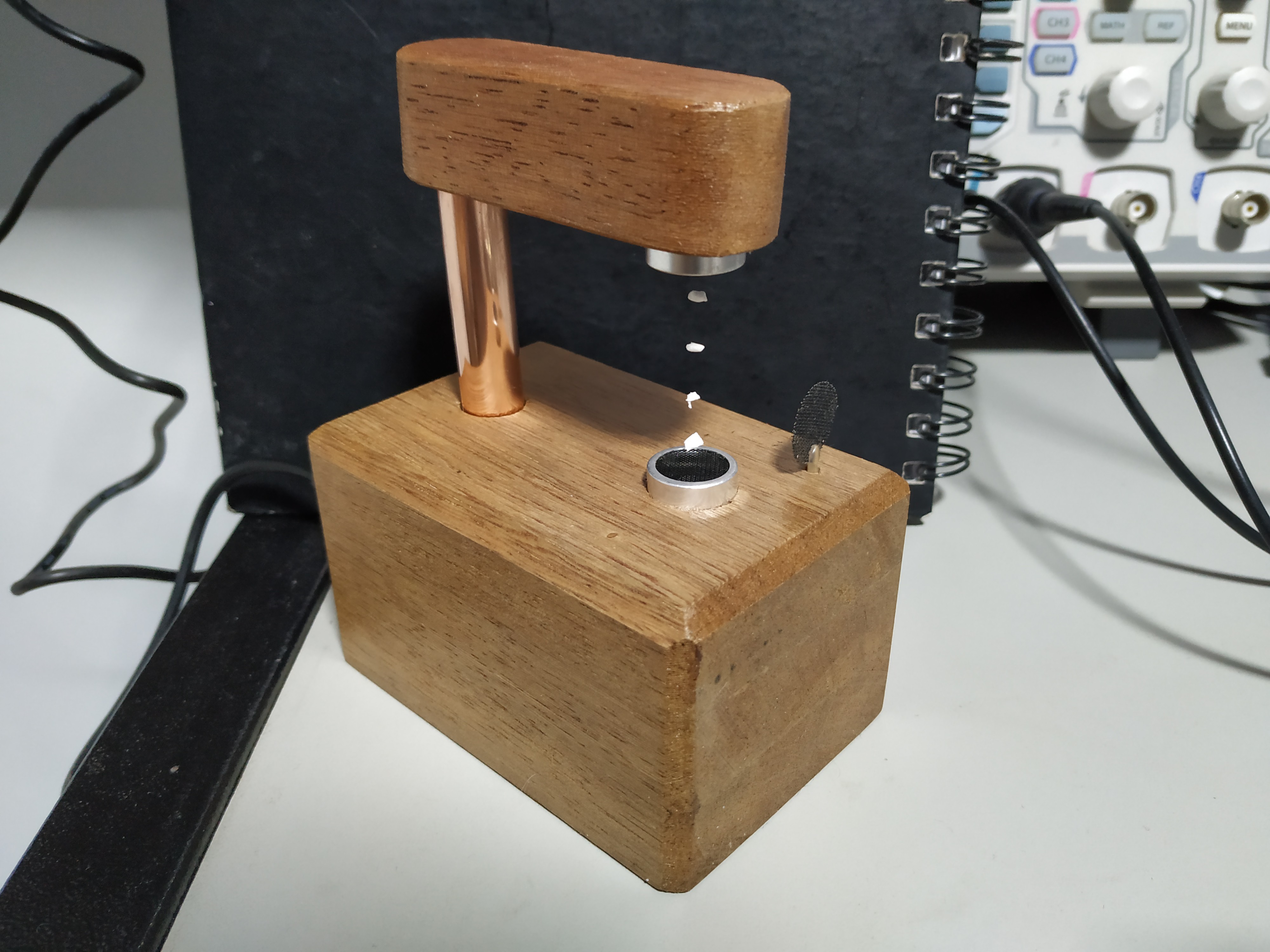
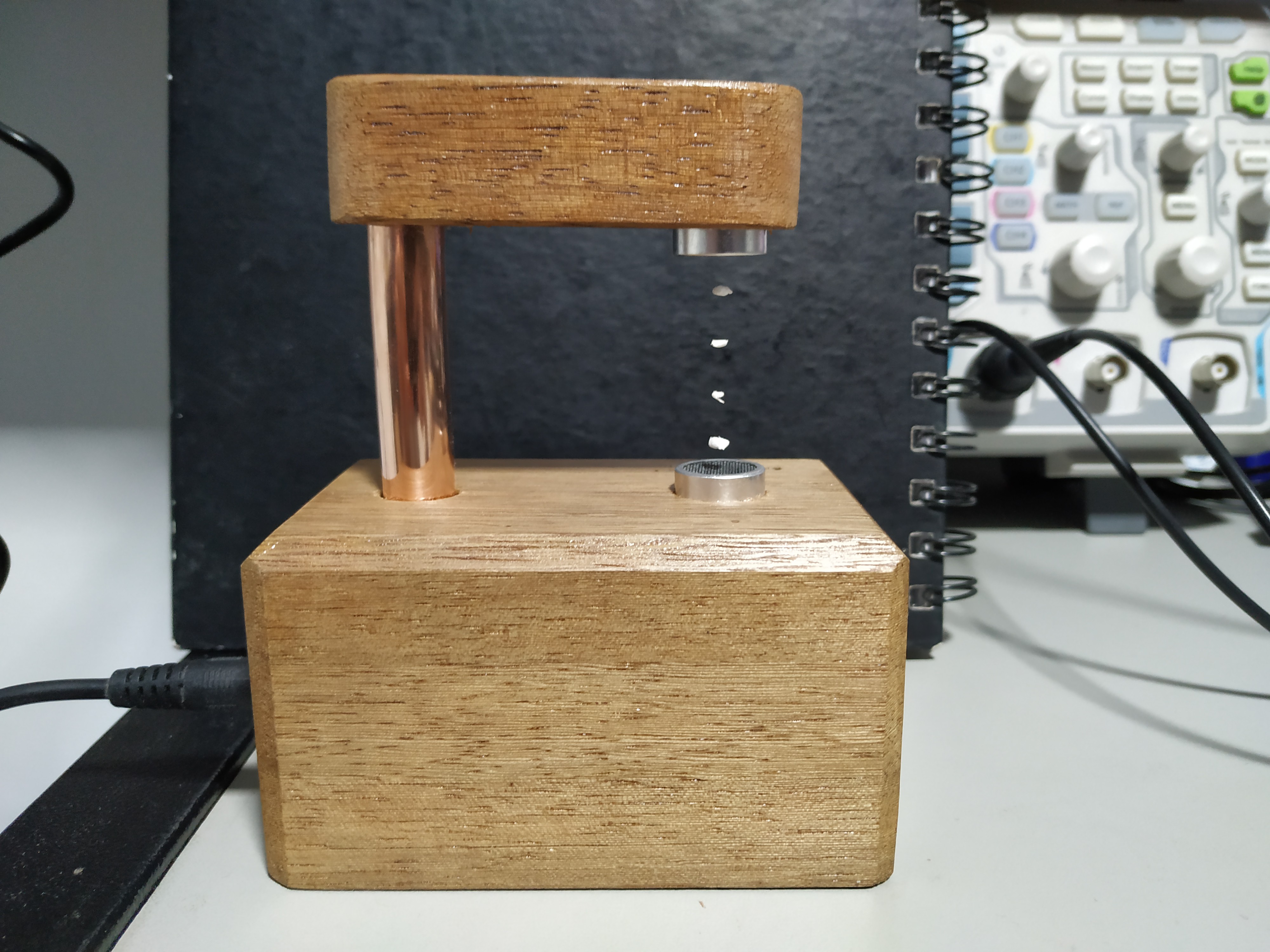
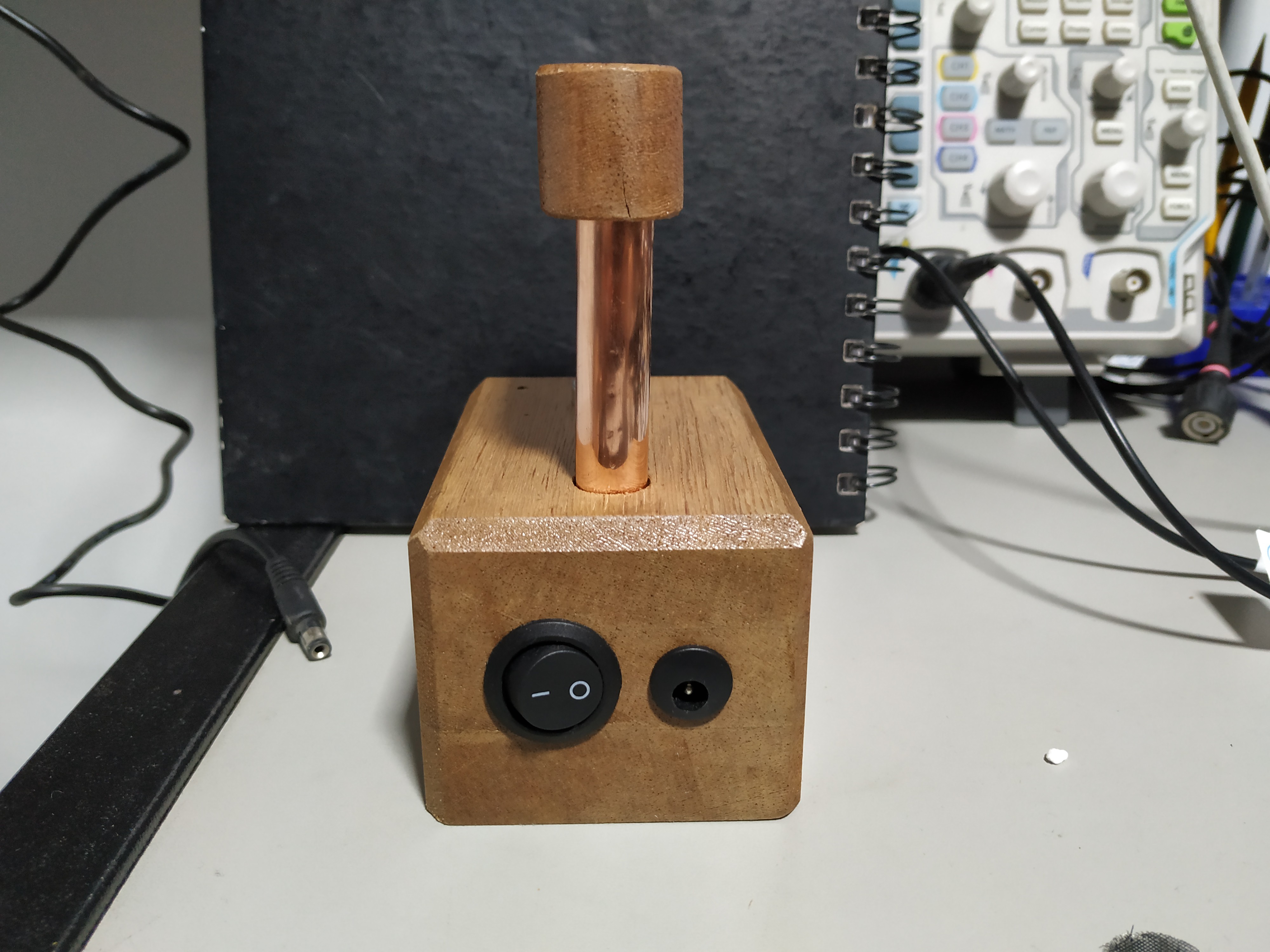
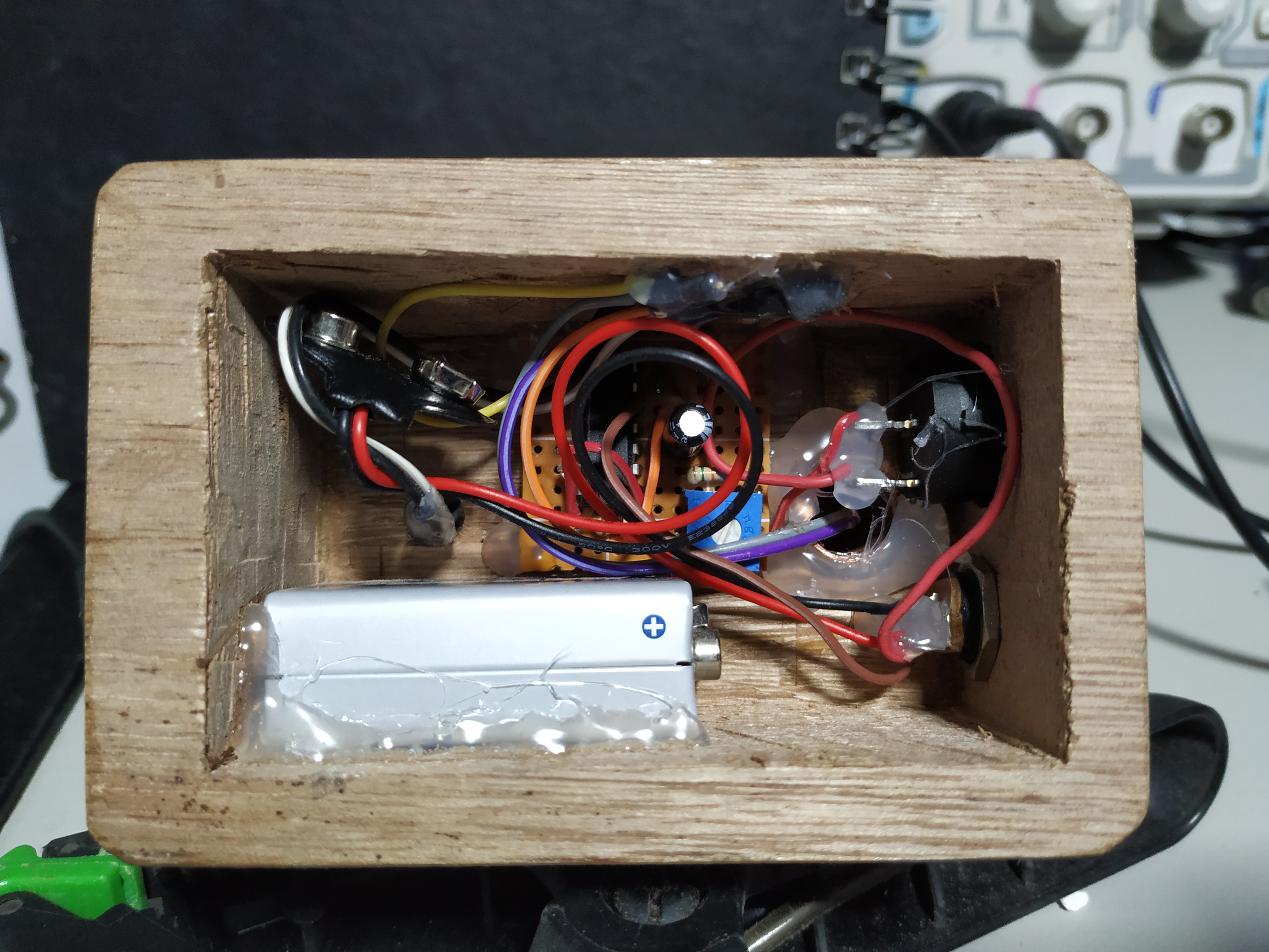
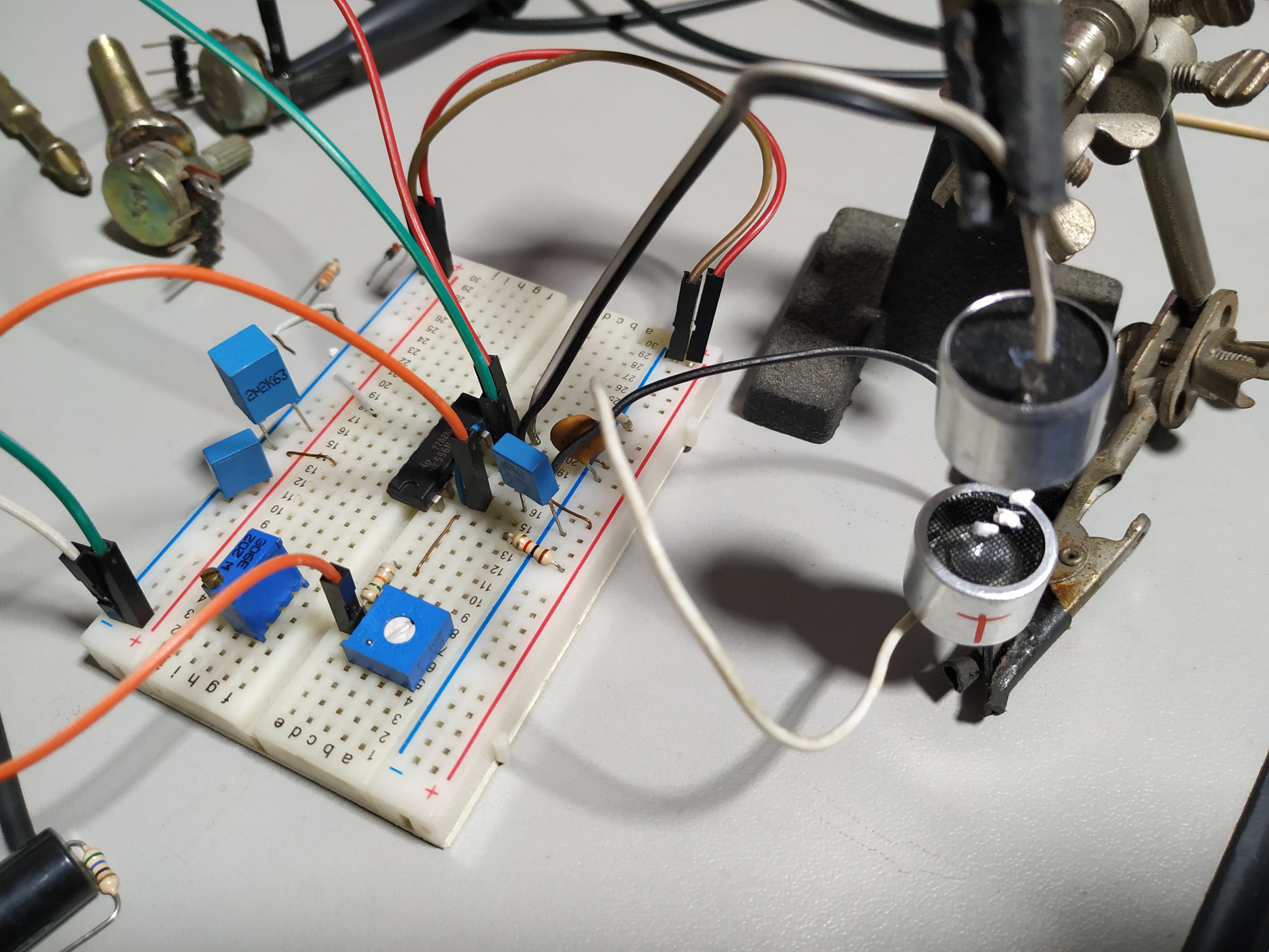
12/24/2021 at 20:52 • 0 commentsBuilt the circuit on a perfboard, got some wood and copper tubing and finished it off. Not much to say, the circuit is exactly as the first schematic, using both timers on the 556. I tried using a 9V battery, but it wasn't enough, the circuit needs at least 12V to work properly.
![]()
![]()
![]()
![]()
-
New prototype
12/21/2021 at 08:26 • 0 commentsWith the schematic on hands and shuffling through my things to find where I had these transducers, I built the new prototype. Instead of using both 555 on the 556, I got it to work with a single 555. The downside is that the circuit must be powered with at least 12V for it to work properly.
![]()
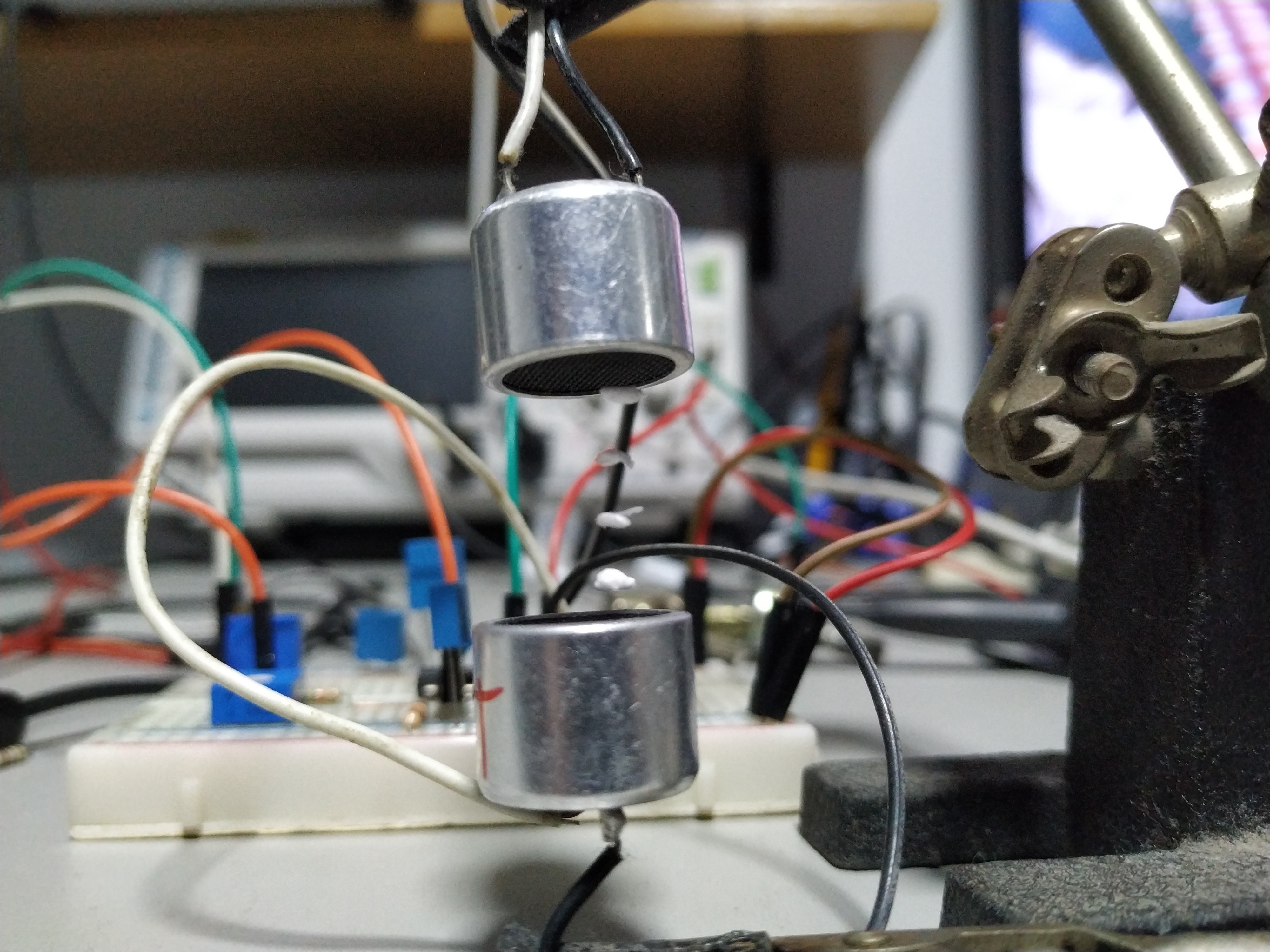
Here it is levitating four polystyrene pieces.
![]()
-
First prototype and schematics
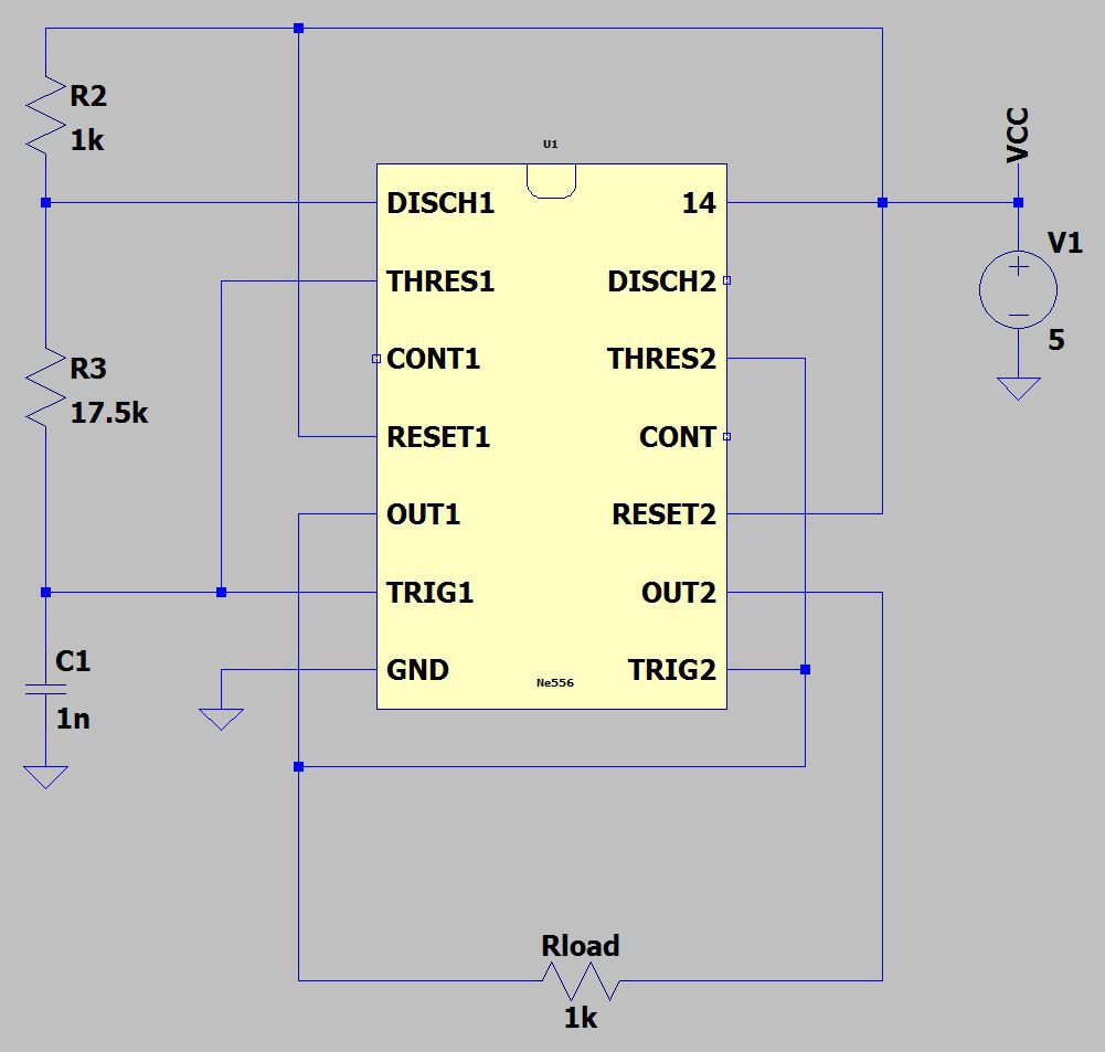
12/21/2021 at 08:18 • 0 commentsMy first prototype used two 555 (actually a 556) to levitate the small polystyrene pieces. The idea is simple, you generate a 40kHz signal with the 555 in astable configuration and feed it to both transducers. Adjust the distance between the transducers and fine tune the frequency.
The second 555 was used in an inverting configuration, that way you can make a self-oscillating H-bridge, increasing the power delivered to the transducers.
This is the circuit I'll be building this time. Rload is actually the transducers and R3 will have a potentiometer to fine tune the frequency.
555 ultrasonic levitation
Accepting the challenge made in a previous Hackaday post.
 Kuro
Kuro