Sam Ettinger
-
Origami time
02/06/2022 at 17:44 • 0 commentsOn 2-2-2022, I established that I don't need 2 PCBs. I just need one that folds.
I knew I wanted to try sandwiching an ATtiny84A between two flex PCBs, but before this I had been envisioning two disconnected PCBs, held in place with some structural solder or something along those lines. But then I saw this cursed connector by Joey Castillo, which got me thinking about a folding connector instead. Joey got it to work for a single-sided 5-trace Micro-USB connector, would it work for a two-sided 24-trace USB-C connector?
![]()
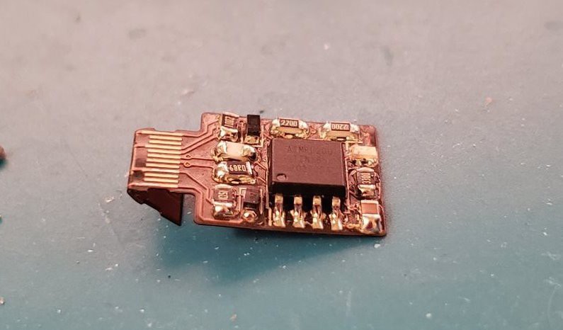
I'm delighted to say that the folded flex USB-C works. For this demo I didn't want to use one of my precious BGA chips, so I went with a hand-solder-friendly ATtiny85 circuit like the Nanite or Digistump uses.
Of course, using two flex PCBs adds some thickness. With OSH Park flex PCBs, an ATtiny84A sandwich would be around 0.9mm thick. Other vendors default to thinner substrates, but their prices are significantly higher for wee PCBs like mine. Anyway, I'm no longer adhering to the 0.7mm thickness requirement, let's get weird 😎
-
The single-sided boards that I tried (and don't plan to pursue further)
02/06/2022 at 05:43 • 0 commentsI realize now that a lot of the content I'd put in the "Project Details" section gets rapidly obsoleted, so I should be putting it in project logs instead. For example, the four demonstration projects that I described are no longer the ones I care about—I got one of them to 67% functionality and learned enough in the process that it wasn't worth pursuing the other designs. Here is some info about those designs, which originally was in the "Project Details" section.
Demo 1: RGB LED that can't be programmed over USB
![]()
![]()
![]()
![]()
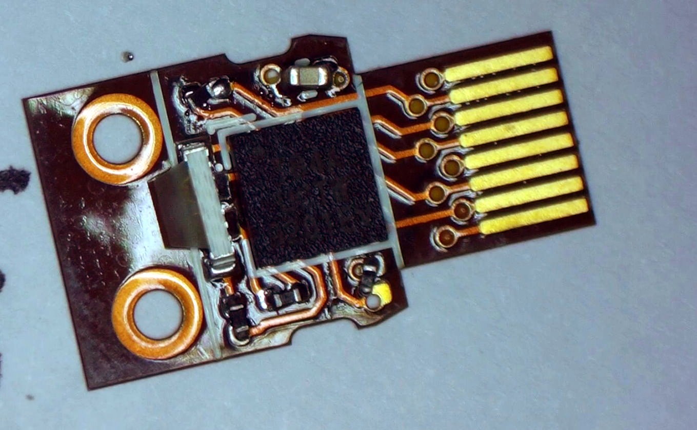
When initially assembled, that 8-row FFC connector serves as a handy way to program the microcontroller. Once programmed, the connector can be sliced off; the remaining part fits snugly inside a USB-C cable. An RGB LED pokes out of the end, along with a tab that lets you pull the PCB back out again. Out of spite for, uh, myself, I have labelled that the "cowards' tab," encouraging myself to remove the tab and make the board impossible to extract. This would reduce a useful cable into little more than a soothing blinking light for all eternity.
In a twitter thread, I documented the process of assembling this board. It was very fun! I learned that a layer of conformal coating was not sufficient to cover the components—the contacts in the USB-C cable quickly scraped away the coating and consequently led to shorts and burnt-out LEDs. I also learned that gently pulsing green and blue (as opposed to red green and blue) looked extremely soothing, so I felt less bad about abandoning the red channel in future designs.
Even if the conformal coating had worked, the layout created its own issues. I should have controlled the RGB LEDs using the OCR0A/OCR0B/OCR1A/OCR1B pins for easy PWM adjustment. Instead, I had to resort to binary code modulation to achieve any sort of brightness control. It's working alright, as shown here (and further down that thread). And honestly it's a good excuse to play with binary code modulation, it's fun!
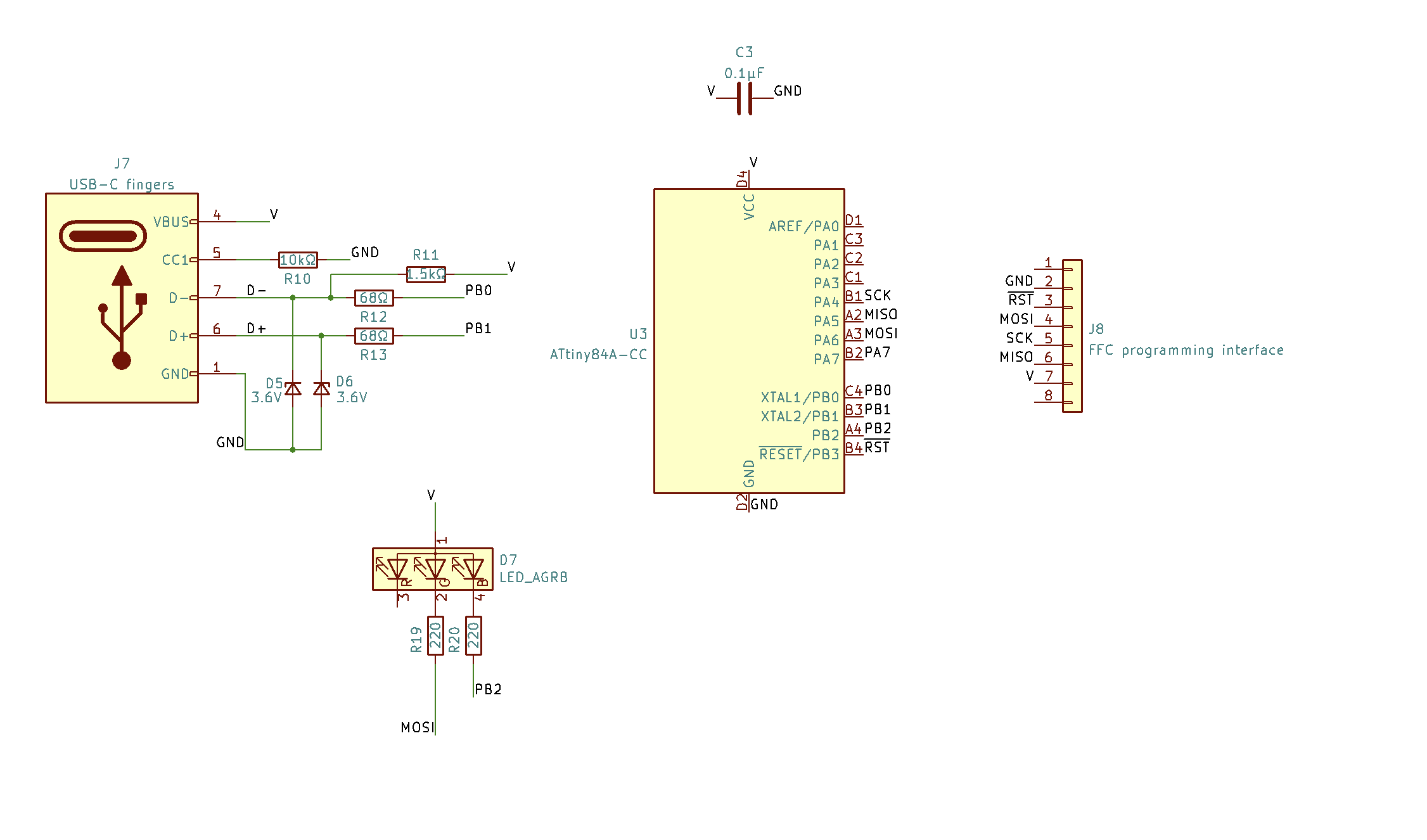
Demo 2: RGB LED that can be programmed over USB
![]()
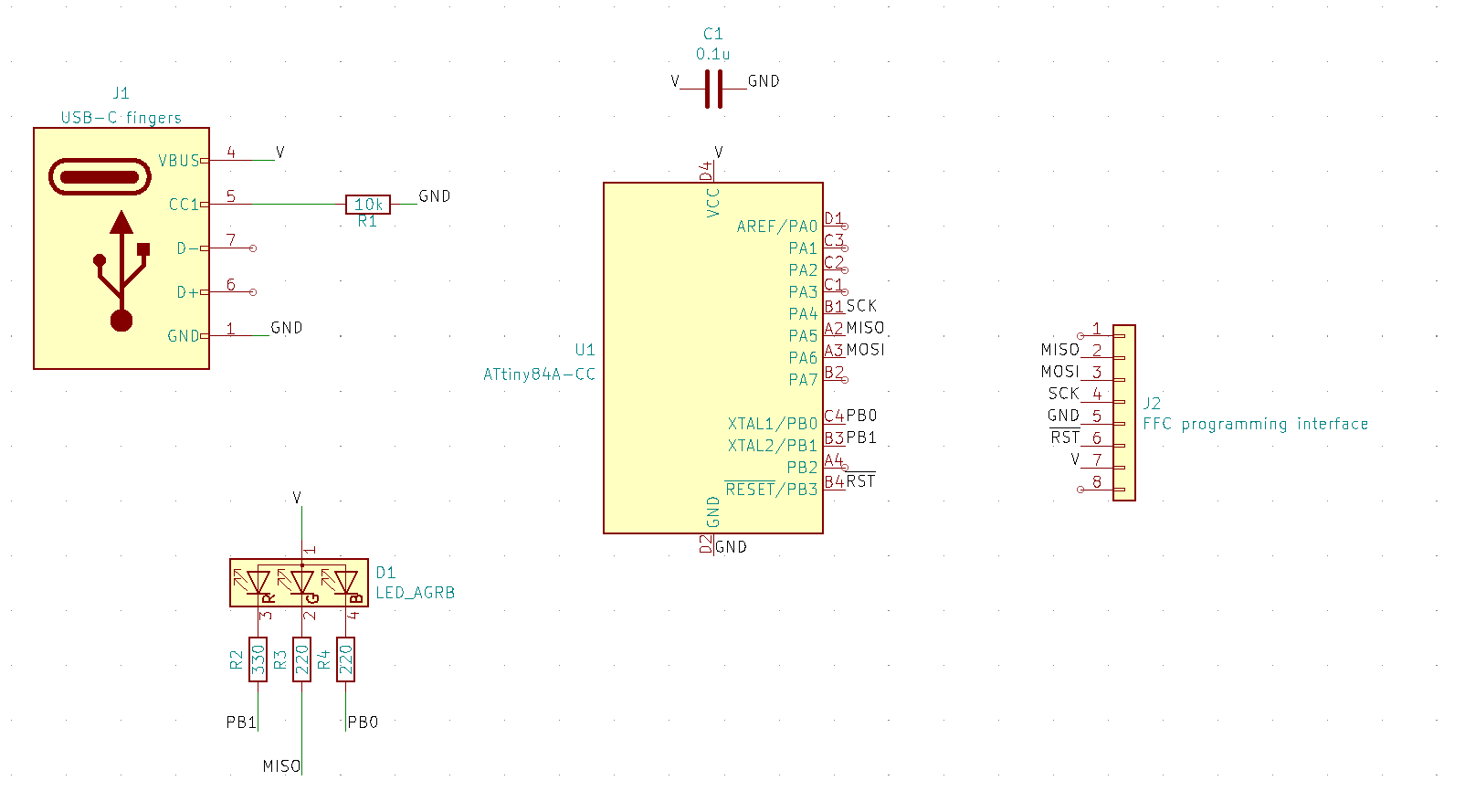
It would be nice to use the USB data lines to program the microcontroller! I didn't attempt this for the Demo 1 because I wanted to keep the board as uncluttered and simple as possible. When I started routing this, I didn't find a way to connect all three LED channels, so I've elected to give it green-and-blue LED control only.
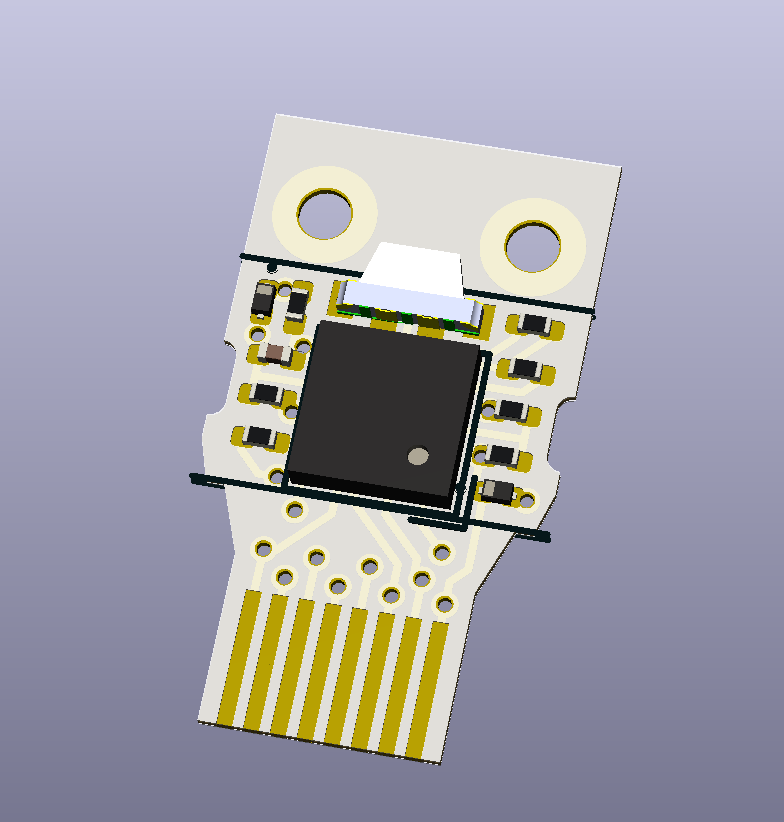
All that's required are five extra components: a pullup for the D- line, small resistors on the D- and D+ lines, and zener diodes as level shifters. This is the low-complexity approach used on the Digispark and its derivatives. I have not attempted to make this board yet. Also, look at the 3d render above; doesn't it look like an owl? I love it.
There is an interesting issue with the USB communication. In the USB-C standard, the D+/D- lines are only connected on one side of the plug! It assumes that the USB-C port has D+/D- connectors on both sides, so the plug orientation should not matter. But our USB-C port only has D+/D- connectors on one side. We've reintroduced the classic USB behavior of having to flip the device over 3 times before it works!
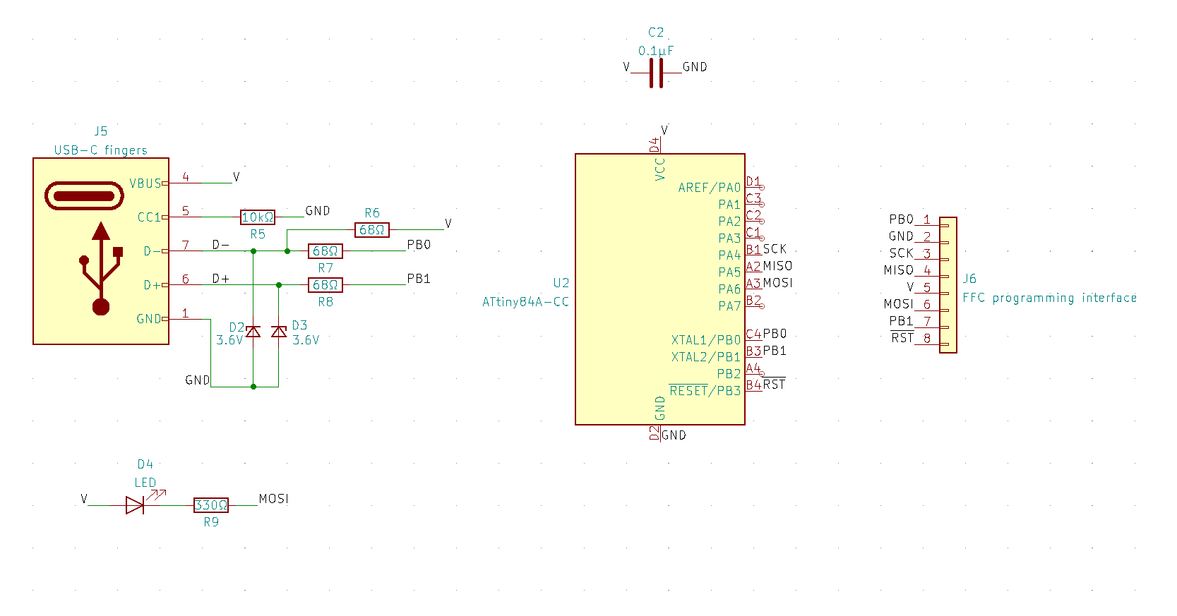
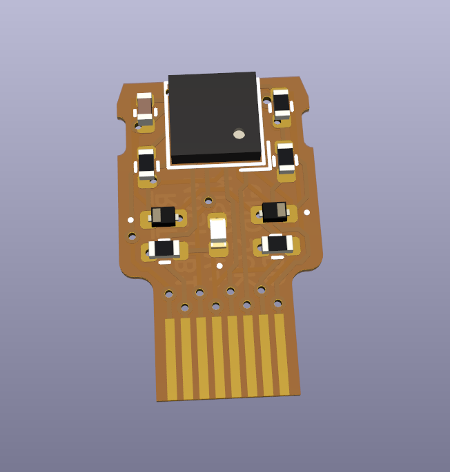
Demo 3: Basically a Digispark
![]()
![]()
In this version, the FFC portion is meant to stay attached! And all the components are 0402-sized with generous spacing so I can worry less when soldering. As a result it can be used in a slightly more "normal" fashion—still operable by sticking it inside a USB-C cable, but now there's a breakout of sorts.
Demo 4: "Coulda used a 555"
![demo4render.png]()
In the past I've poked fun at the "coulda used a 555" refrain by, among other things, using three microcontrollers where a 555 would suffice, and using a 555 Schmitt Trigger where a single SPST button would suffice. As luck would have it, there is a BGA 555 IC that is just shy of 0.6mm tall! I've had to pair it with a 10μF capacitor that is a bit taller, but it's a fun idea to explore later.
-
Repo updated!
01/20/2022 at 01:14 • 0 commentsI've finally gone and pushed some updates to the git repo. Demo 2, the one that's programmable over USB, was not in the repo until now; this is because I completely forgot I hadn't routed the PCB before I published the project! When I did start routing, I didn't find a way to connect all three LED channels, so I've elected to give it green-and-blue LED control only.
In addition, I've added a fourth demo, which uses two 555 BGA ICs instead of an ATtiny84A. This is thanks to some "Coulda used a 555" comments on the post that made the Hackaday blog. Sadly I couldn't get those boards in time to enter the 555 contest, but it's still worth a go I think.
I have a few ideas for how to address the short-circuit problems I encountered with the PCB I assembled previously. The obvious solution is to slap another flex PCB on top, which will create a double-sided USB connector. However, that would end up being about 0.85mm thick, which I worry would cause too much downward scraping force on the flex PCBs. There are vendors with thinner polyimide substrates, which I will look into.
-
Some updates
01/01/2022 at 19:38 • 0 commentsI failed to maintain a Single Source of Truth for this project—there's this HaD.io project, the git repo, and a twitter thread. The twitter thread has newer details than the other two, so here's are the highlights!
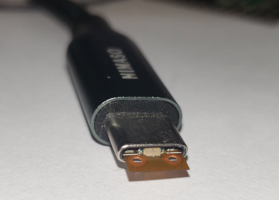
After the thread started getting attention, I went ahead and just cut the flex connector off, thereby locking in the code that was on the ATtiny84A at the time. It did nothing when I put it in a USB-C cable connected to a wall wart, I have not tried plugging it directly into a computer at this time. But I did jury-rig a power-only setup using a micro-USB breakout and a USB-C breakout. Red and blue worked, but then something crackled and damaged the red and green LEDs. I know, right? What a surprise, pushing the exposed components against long parallel rows of conductive fingers caused problems! So I soldered a new LED on and applied two layers of conformal coating. That worked great for the duration of one tweet, then red stopped working. The conformal coating that I have is not strong enough to resist the scraping motions of the USB contacts, apparently. But I was left with a very pleasant blue-and-green doodad, which was fine by me. That was a good stopping place and I haven't had the chance to go back to it since then.
I've since measured the OSH Park PCB to be closer to 0.2 mm (8 mil), thicker than I imagined. This makes it a bit harder to do what I want to do next, which is a """proper""" double-sided port made of two flex PCBs sandwiched around a microcontroller. If the current setup is 0.7mm, putting another 0.2mm board on top will be way too thick. Two possible things to try:
- an even shorter microcontroller. Do you know of one? The ATtiny20 in WLCSP-12 is at most 0.53 mm tall, are there any other options out there?
- cut a hole in the second flex PCB so the microcontroller can poke through but the other components are shielded. This needs a diagram to illustrate what I mean, I think, but I can't make one at the moment.
A USB-C connector on a flex PCB
Let's use an ATtiny84A as a structural element!