strange.rand
-
Integration with Home Assistant, bug fixes
11/23/2022 at 21:38 • 0 commentsJust a quick update. The Power Monitor works almost a year without severe issues. As I expected, the OLED started to fade, so switching the display off base on a light sensor (or whatever) is essential (but won't be implemented in this hardware version).
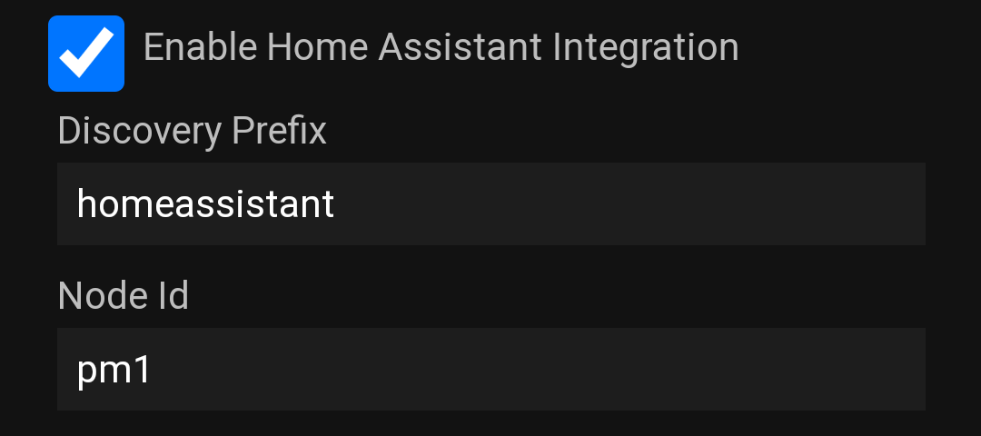
As I'm playing with Home Assistant, I decided to add auto-discovery to the device to simplify integration. New options on the settings page:
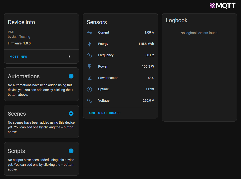
And this is how HA displays it:
Additionally, many bug fixes were added recently to improve stability and code quality. BTW, the charts were entirely removed.
That's all for now.
-
Time sync, reset energy (manual), and charts
01/19/2022 at 07:24 • 0 commentsHere is a short (hopefully) log about the recent updates.
Time sync (NTP)
During searching for an optimal NTP library for ESP32, I've found out that the time syncing functionality can be added simply by including <time.h> header.
First, we need to configure time. It can be done in two ways:
- using configTime(<GMT offset>, <DST offset>, <NTP server>)
- using configTzTime(<timezone>, <NTP server>)
The second option is a great way to automatically handle switching to daylight saving time. The required timezones can be found here: zones.csv. Then we can use getLocalTime method to retrieve a local time. Time syncing will be executed automatically every hour (by default).
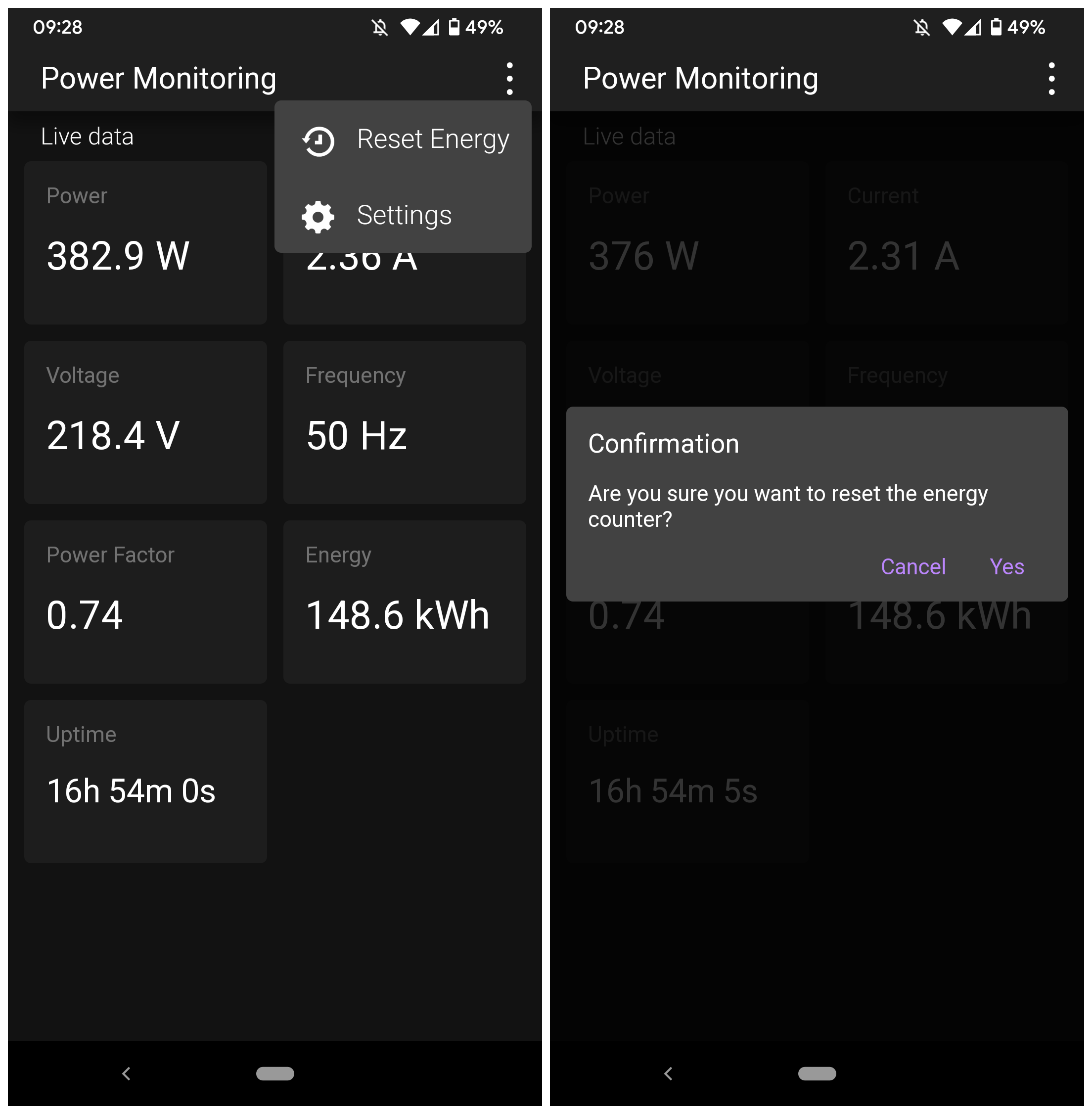
Reset energy
It can be done using a new menu:
![]()
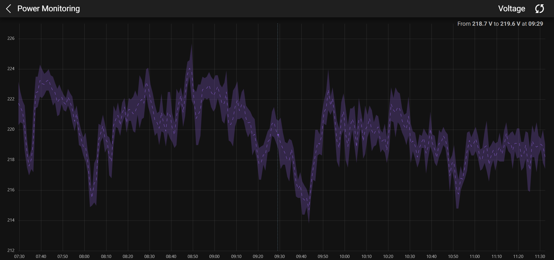
Charts
This is the most controversial functionality (or the most useless one). I wanted to store and show power and voltage for the last 12 hours (it's enough for basic stuff). Let's do quick math:
12 × 60 × 60 = 43200 datapoints
(4 + 4 + 4) × 43200 = 12 × 43200 = 518400 bytes
It is a lot, so I decided to aggregate data per minute, that's reduces needed memory to 8640 bytes. After additional thinking, the decision to store min and max was made, so the final structure looks like this:struct ChartData { uint32_t date; float minVoltage; float maxVoltage; float minPower; float maxPower; };Two circular buffers are used to store the values. One is processed and cleared every minute, and one is for "permanent" storage.
CircularBuffer<ChartData, 720> chartBuffer;
CircularBuffer<TempChartData, 60> tempChartBuffer;
ArduinoJson library is not used to build the final JSON response to additionally reduce memory consumption.
Selecting a proper chart library was hard. I started from Google Charts, then tried ChartJS, one or two other libs, and then finally uPlot. It is small, fast, and has enough features to display what I want though, it also has a big disadvantage – pure documentation.
![]()
Even considering that the chart supports zooming and panning, using it on the smartphone isn't comfortable. But it was an interesting process to build it. One additional thing I like to try here – streaming data directly from the circular buffer without an intermediate char array (it'll drastically reduce memory consumption).
Next steps
- An automatic reset of the energy counter
- Refactoring
- Bugfixes
-
Settings and WebApp
01/07/2022 at 12:08 • 1 commentMany things were added/improved during the last few days:
- Settings added (EEPROM storage is used)
- Improved serving of static files
- Introduced an automated build process for WebApp (using Webpack)
- build-in dev server with hot reload
- production build
- minification of files
- file compression (gzip)
- inline SVG icons (to serve fewer files)
- Restructured WebApp
- Added caching
- Added notification about an update available (PWA specific, more details later)
- Possibility to install the app is added
- Improved UI/UX
![]() ---------- more ----------
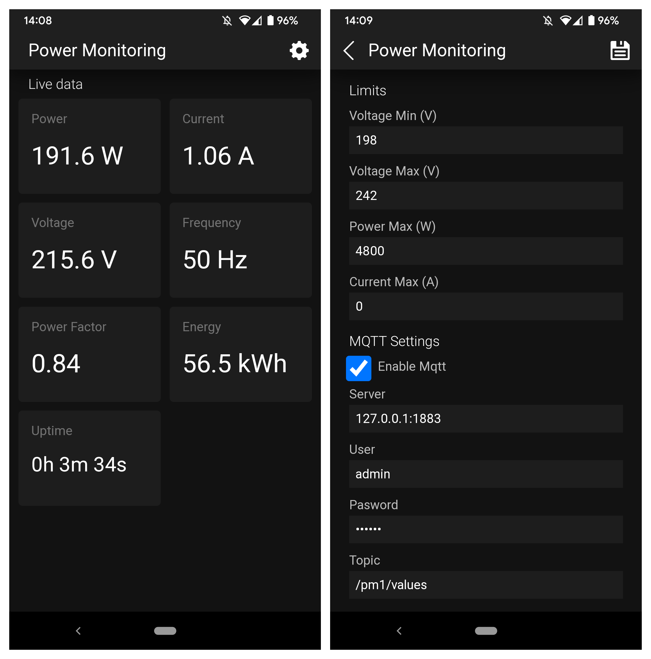
---------- more ----------Settings
Now we can configure:
- Limits: min/max voltage max power and current
- MQTT: server, port, user & password, topic
- System: OTA password and how often the module should request new data from the sensor
There is no validation on the server, so I wouldn't say that everything is super secure and production-ready, but it works. To simplify server-side code, all fields are combined into a single structure so in that way, we can read/write everything at once.
The only tricky part was receiving a JSON to later parse it using the ArduinoJson library.
server.on("/power/api/settings", HTTP_PUT, [](AsyncWebServerRequest *request){}, NULL, _saveSettings);
... ... ...
void _saveSettings(AsyncWebServerRequest *request, uint8_t *data, size_t len, size_t index, size_t total)
{
    ... ... ...
}
Depending on the body size, a request callback can be executed once or a few times. In my case, I had two executions of the callback, and getting a single JSON result requires additional logic (plus an intermediate buffer). The current code looks like this:
void _saveSettings(AsyncWebServerRequest *request, uint8_t *data, size_t len, size_t index, size_t total)
{
    if (total > sizeof(dataBuffer))
    {
        request->send(500, CONTENT_TYPE_TEXT, "Content is to big");
        return;
    }

    memcpy(dataBuffer + index, data, len);

    if (len + index < total)
        return;

     // JSON parsing here
}
The dataBuffer defined in main.cpp. First of all, we check whether the total body size is bigger than our intermediate buffer if yes, we won't be able to receive data and have to report an error. Then we copy the data into the buffer starting from the particular index, and if we haven't received all data (len + index < total) stop execution. In that way, only the last executed callback will do real work (parsing and saving).
As you probably noticed, the current approach is not suitable for a multi-user scenario when two users simultaneously save settings. Maybe, I'll fix it in the future.
Static files and automated build process
Web server configuration was simplified a lot:
server.on("/", HTTP_GET, [](AsyncWebServerRequest *request)
              { request->redirect("/power/index.html"); });
server.on("/power/", HTTP_GET, [](AsyncWebServerRequest *request)
              { request->redirect("/power/index.html"); });

server.serveStatic("/power/", SPIFFS, "/");
server.serveStatic("/power/images", SPIFFS, "/images");
The two first directives redirect a user to index.html, next two serve all static files. Additionally, all static files are compressed by gzip (during the build) to use less space and speed up loading. All SVG icons used from CSS were embedded into the resulting CSS file to have fewer requests and simpler caching.
Playing with Webpack took me more time than the rest of things altogether. But it was interesting, and now it is easier to develop new changes.
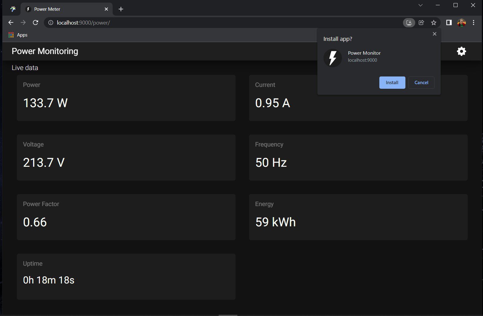
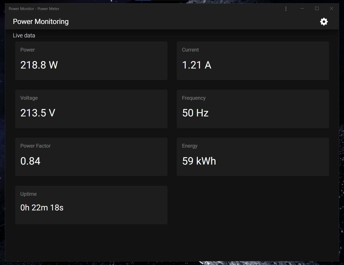
Progressive web app
From the beginning, I wanted to have a progressive web application (PWA) that could be installed on the phone/desktop like a native app. I will not talk about how it works in detail because it is a broad topic, but more information can be found on web.dev/progressive-web-apps or any other resource.
![]()
![]()
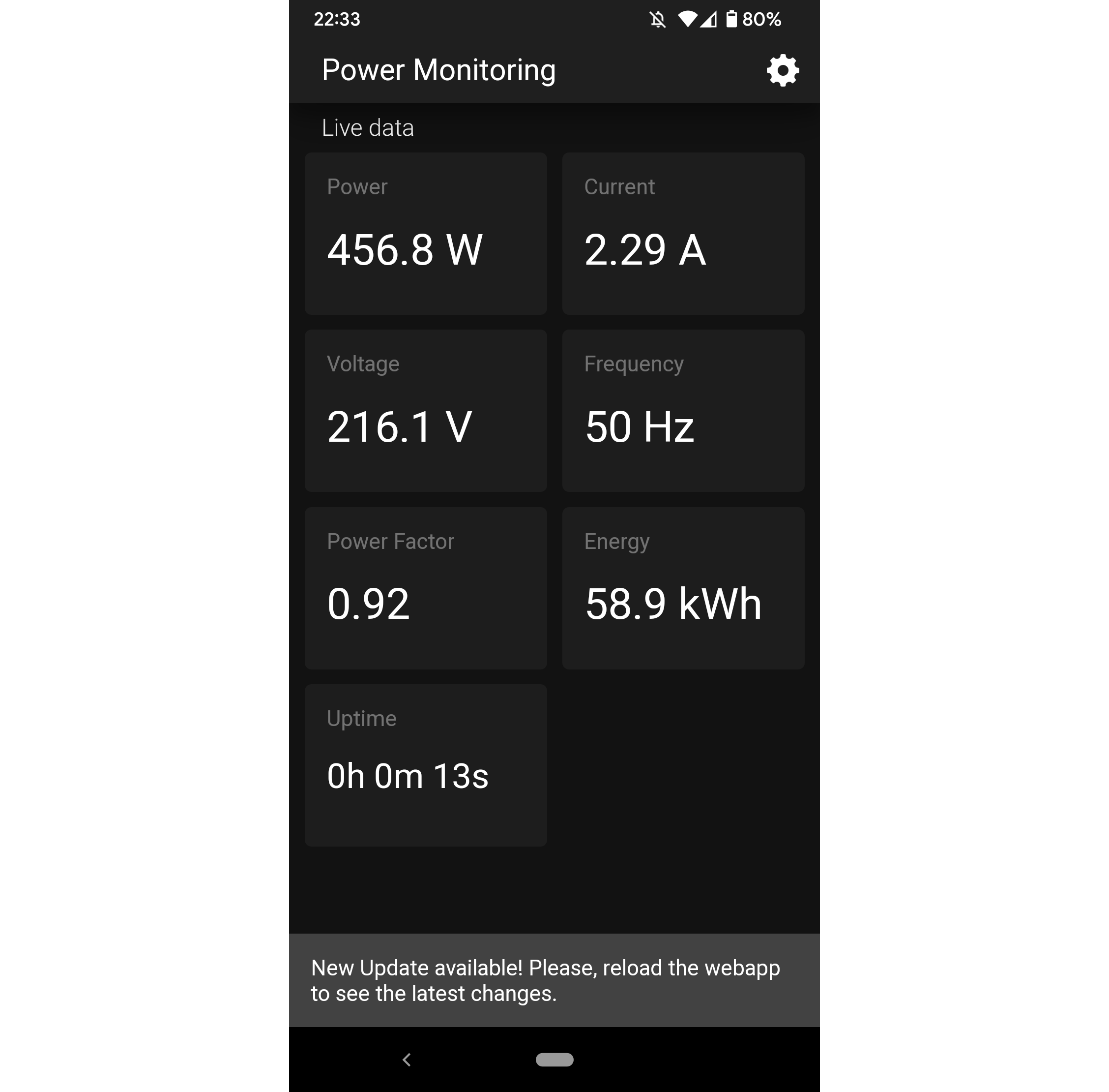
The app uses the cache first strategy, so all files are loaded from the browser cache (even if the network is available). This approach has one pitfall: even when the app is updated on the device/server and the user opens it in a browser, it will see the cached version instead of the new one. To get a new version, the user has to:
- close the app and open it again
- manually refresh the page
The simplest way to handle such a case is to notify the user about using an outdated version. I don't think this functionality is truly needed for this particular app, but it was an excellent time to learn something new.
![]()
I've almost forgotten to add one more important note about PWA. To make it installable, the app should satisfy a few criteria:
- The web app is not already installed
- Meets a user engagement heuristic
- Be served over HTTPS
- Includes a web app manifest that includes:
- short_name or name
- icons - must include a 192px and a 512px icon
- start_url
- display - must be one of fullscreen, standalone, or minimal-ui
- prefer_related_applications must not be present, or be false
- Registers a service worker with a fetch handler
All points except 3rd one are implemented in the application. I don't want to add SSL/TLS support to the device, though it is theoretically possible. In my case, a standalone server with a public IP and dedicated domain is proxying requests to the module. It already has a valid SSL certificate and auto-update functionality using Let's Encrypt. By the way, this is the reason why I configured everything to be served from /power/ instead of the root /.
Next steps
As for now, almost everything planned has already been implemented. The only important thing left is resetting the energy counter at the beginning of the month. I also have a few additional ideas that might be implemented too:
- New property on the settings page to configure screen brightness
- Possibility to reset energy counter via the web UI
- Power/current chart for the last 24 hours (without persistent data storage, so it'll show nothing after the reboot)
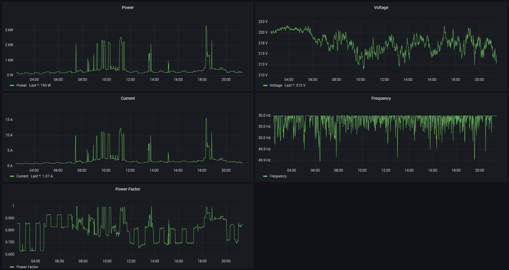
I already have all charts in the Grafana, but adding something to the device itself looks interesting and relatively simple, so why not?
![]()
-
Firmware
01/02/2022 at 07:55 • 0 commentsHow to upload firmware
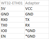
WT32-ETH01 requires a standalone USB to UART adapter for firmware uploading. Wiring:
![]()
Pins IO0 and EN should be connected to GND only to start uploading firmware and then disconnected to allow the normal boot.
To configure wired ethernet, we have to add a few defines. It can be done in the code (in that case, the defines should go before "#include <ETH.h>") or in the platformio.ini using build_flags.
[env:ESP32-PM1]
platform = espressif32
board = esp32dev
framework = arduino
monitor_speed = 115200
build_flags =
    -D ETH_PHY_TYPE=ETH_PHY_LAN8720
    -D ETH_PHY_ADDR=1
    -D ETH_PHY_POWER=16
    -D ETH_CLK_MODE=ETH_CLOCK_GPIO0_IN
Code structure
I like keeping different things in different files instead of having a bulky "main.cpp". Let's see what functionality can be separated:
- Network: connect, configure, reconnect, etc.
- Pzem: get data, reset energy counter (in the future)
- Display: show required information on the screen
- Webserver: configuration, all handlers for URLs, update clients via WebSockets
- MQTT: connect, reconnect, configuration, send data
- Module: some base, reusable functionality
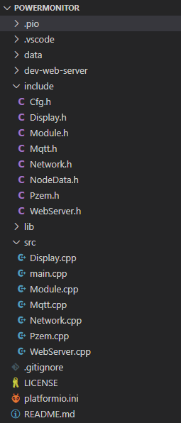
So the current structure is:
![]()
For example, Mqtt.h describes everything related to MQTT. If you want to use a variable that is defined in main.cpp, you have to define it as an external in the Mqtt.h (e.g., extern EventGroupHandle_t eg).
FreeRTOS
As you probably know, the Arduino core for ESP32 uses FreeRTOS, which gives us a lot of possibilities. Let's analyze our needs and check what tasks we have:
- Get data from the PZEM module
- Update display
- Send updates to web clients
- Send data to MQTT broker
The first task is repeatable, and in my case, it should be executed once per second. The next three tasks should be executed only if we have new data to process, so they are event-based.
First of all, we have to define a few things:
EventGroupHandle_t eg;
QueueHandle_t qMqtt;
TimerHandle_t tRequestData;
SemaphoreHandle_t sema_PZEM;
Then in the setup function:
eg = xEventGroupCreate();
qMqtt = xQueueCreate(4, sizeof(MqttMessage));
sema_PZEM = xSemaphoreCreateMutex();

xTaskCreatePinnedToCore(taskRetrieveData, "RetrieveData", TaskStack10K, NULL, Priority3, NULL, Core1);
xTaskCreatePinnedToCore(taskUpdateDisplay, "UpdateDisplay", TaskStack15K, NULL, Priority3, NULL, Core1);
xTaskCreatePinnedToCore(taskUpdateWebClients, "UpdateWebClients", TaskStack10K, NULL, Priority3, NULL, Core1);
xTaskCreatePinnedToCore(taskSendMqttMessages, "tMqtt", TaskStack10K, NULL, Priority2, NULL, Core1);
tRequestData = xTimerCreate("RequestData", pdMS_TO_TICKS(Cfg::requestDataInterval), pdTRUE, (void *)0, reinterpret_cast<TimerCallbackFunction_t>(requestData));
The request data method is just one line of code
void requestData()
{
  xEventGroupSetBits(eg, EVENT_RETRIEVE_DATA);
}
It fires an event using the event group (eg) defined above. Theoretically, we can do real work here, but without blocking, so better to have a separate task.
EVENT_RETRIEVE_DATA is defined in the Pzem.h like this
#define EVENT_RETRIEVE_DATA (1 << 1)Below you can see simplified code for retrieving the data. It waits for the event, takes a semaphore and retrieves the data, then gives the semaphore back, fires events to update display and web clients, and finally, composes MQTT message and pushes it to a queue. All other tasks are based on the same principles.
void taskRetrieveData(void *pvParameters)
{
    for (;;)
    {
        xEventGroupWaitBits(eg, EVENT_RETRIEVE_DATA, pdTRUE, pdTRUE, portMAX_DELAY);

        if (xSemaphoreTake(sema_PZEM, TICKS_TO_WAIT12) == pdTRUE)
        {
            // read data from PZEM here

            xSemaphoreGive(sema_PZEM);
            xEventGroupSetBits(eg, EVENT_UPDATE_DISPLAY | EVENT_UPDATE_WEB_CLIENTS);

            MqttMessage msg = composeMessage(data);
            if (xQueueSendToBack(qMqtt, &msg, 10) != pdPASS)
            {
                debugPrint("Failed to add to the mqtt queue");
            }
        }
    }
}
As a result
- We have a neat and clear code structure
- Software timer is used to initiate a repeatable task
- All other tasks are data-driven
WebSockets
One of the project's features is the web app that shows real-time data. The simplest and fastest way to implement this functionality is using WebSockets.
The WebSocket API is an advanced technology that makes it possible to open a two-way interactive communication session between the user's browser and a server. With this API, you can send messages to a server and receive event-driven responses without having to poll the server for a reply.
The code we have to write is minimal as all sophisticated logic is implemented inside the ESPAsyncWebServer library. All we need to do is to put the required data inside a buffer and then send it using
ws.textAll(buffer);The web client is a simple HTML page with additional CSS styles and JS code. I'm thinking about rewriting it in a bit more fancy way but without using frameworks (pure JavaScript/"Vanilla.js" only).
All code can be found on GitHub.
-
Heating
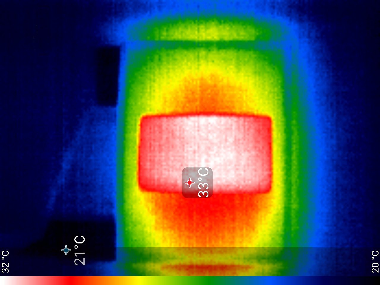
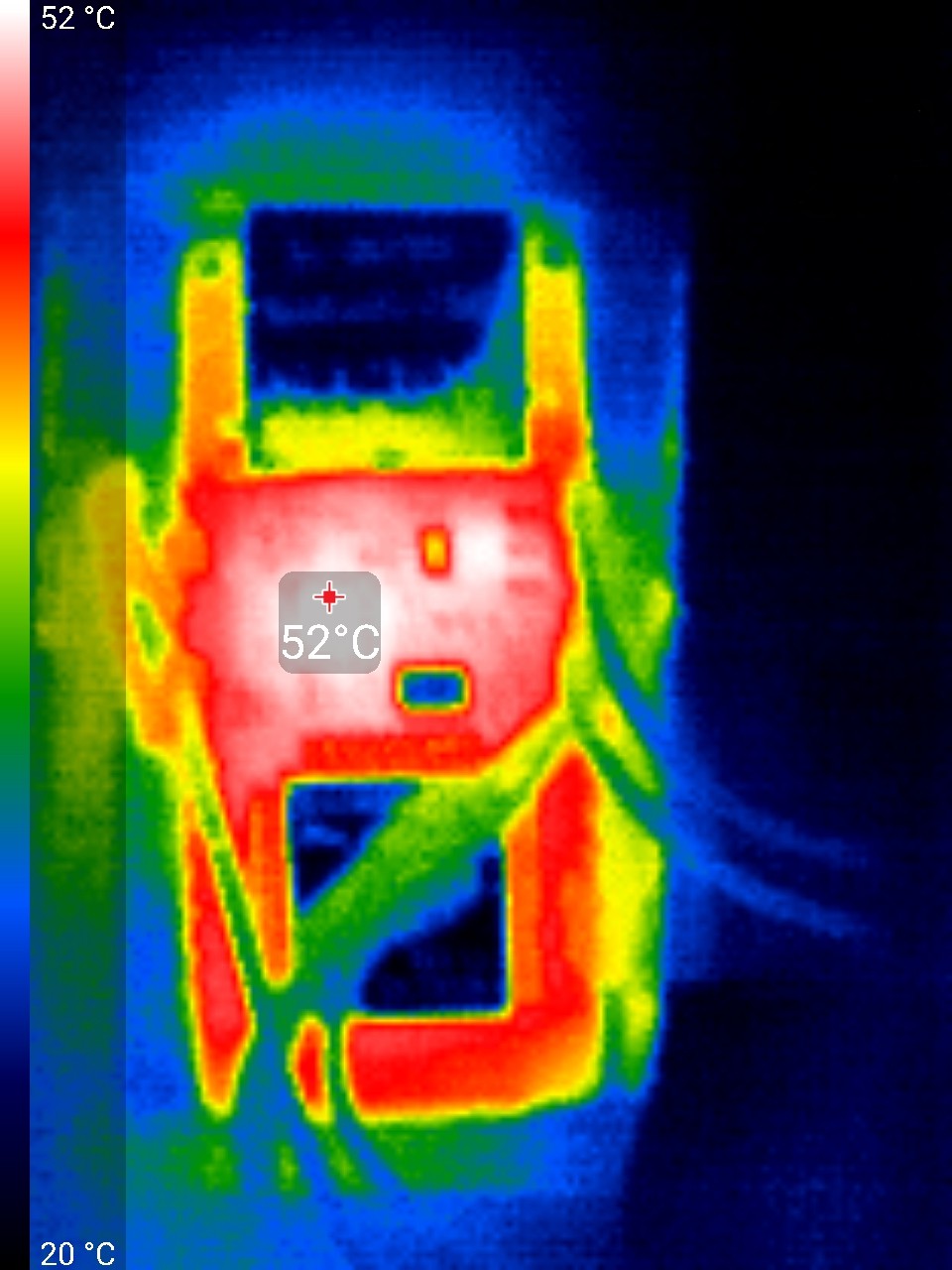
01/01/2022 at 17:02 • 0 commentsA few thermal photos of the module and its components:
![]()
Front view ![]()
WT32-ETH01 I didn't expect that this board could produce so much heat.
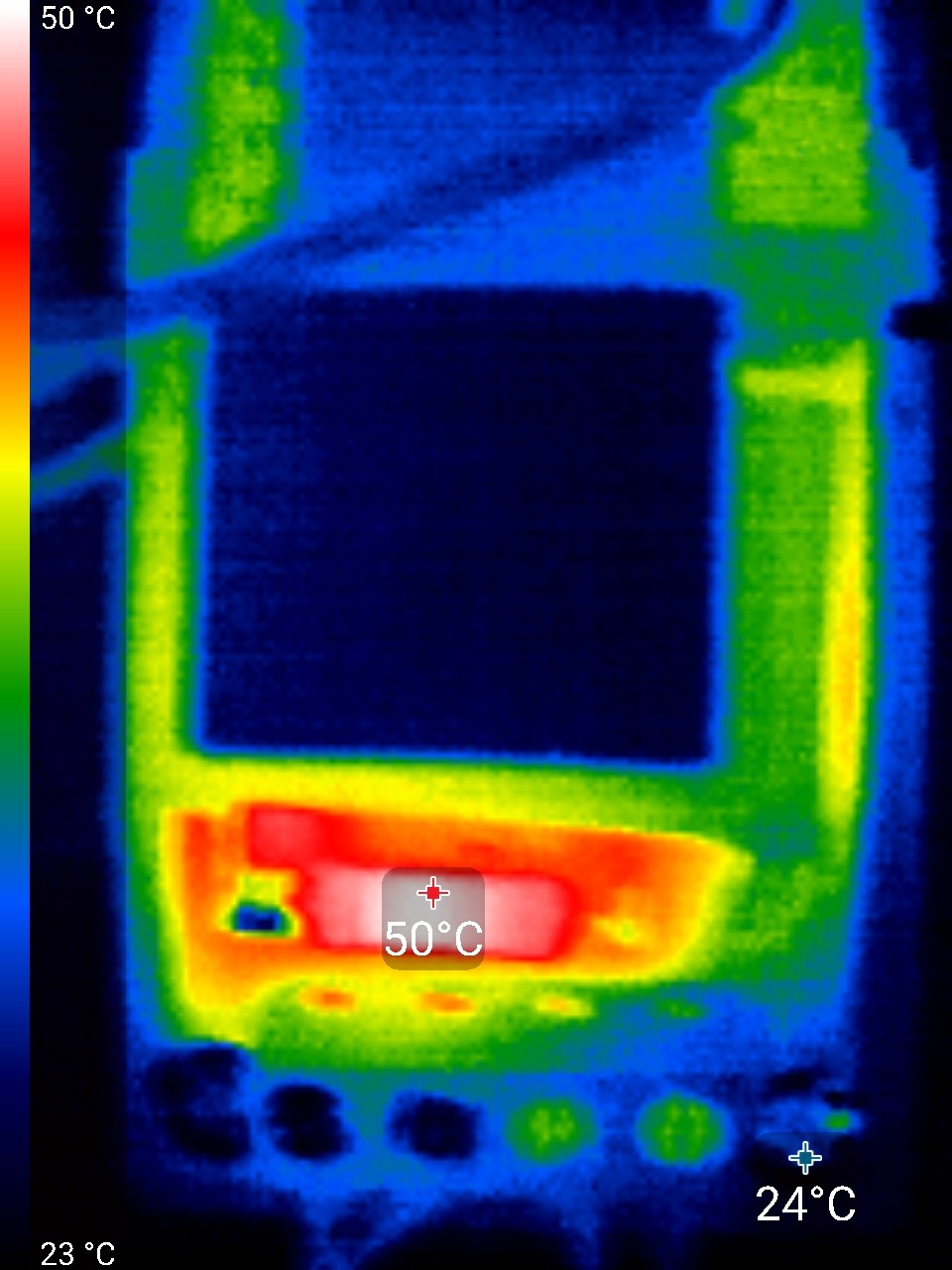
![]()
PZEM-004T v3.0 The hottest part here is a resistor.
Overall, it is okay, but better to use something more thermally resistant than PLA for 3D printed parts.
-
Hardware
12/31/2021 at 14:59 • 0 commentsThe module consists of 3 main components:
- PZEM-004T v3.0 – an upgraded version of energy meter
- WT32-ETH01 – well knows ESP32 but with wired ethernet connection
- OLED display (SSD1308 128x64)
A few words about the component choice. WT32-ETH01 was chosen because I don't want to rely on WiFi and need a wired ethernet connection. There are a few alternative bords, but this one is relatively small and cheap. Instead of an OLED display, I'd rather use a color TFT (IPS), but they require an SPI bus that we don't have on WT32-ETH01.
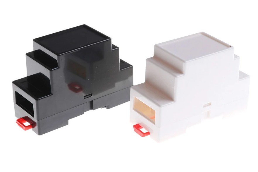
The module should be mounted on a DIN rail, so compatible housing was ordered from Aliexpress.
![]()
PZEM-004T PCB does not fit into the bottom part of the housing; it is a bit too wide in the middle, where the latch is, though it can be easily fixed with a file.
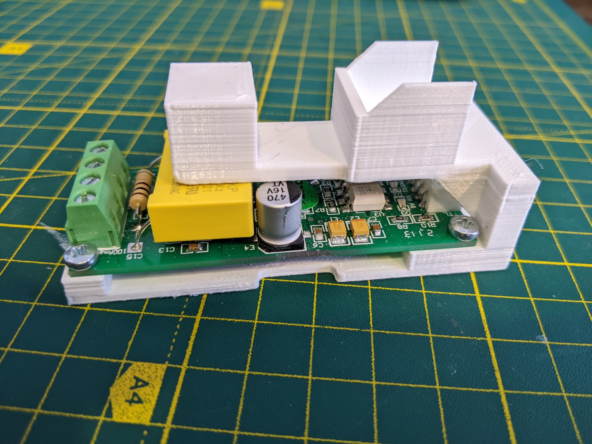
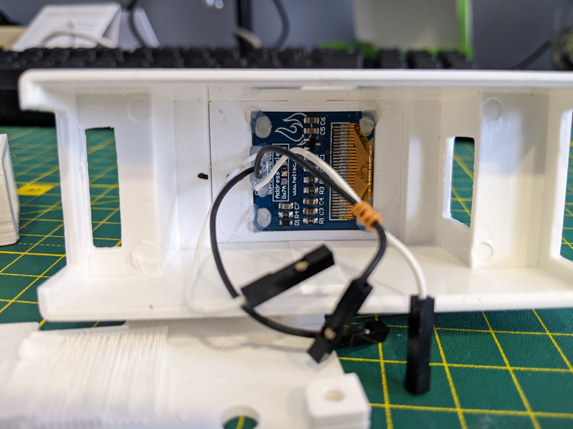
To secure everything in place, I modeled and 3D printed a custom "holder" that you can see in the photo below:
![]()
It has holes to screw PZEM-004T PCB, and it also stops WT32-ETH01 from moving around (especially when connecting ethernet cable).
To secure the screen, one more part was 3D printed and the screen was hot-glued to it. Then the whole sandwich was hot-glued to the housing itself. All required holes in the DIN rail housing were made by drill and a file (they are way from perfect).
![]()
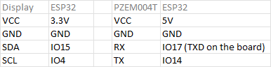
The final part is to wire everything up. I use thin, manually crimped silicon wires for this (also from Aliexpress). Pay attention that RXD pin is not usable on the board, so IO14 was used instead.
![]()
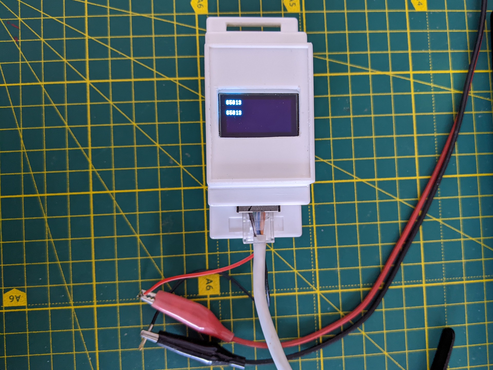
Unfortunately, I didn't find a neat way of connecting power to the module, so I just left wires.
![]()
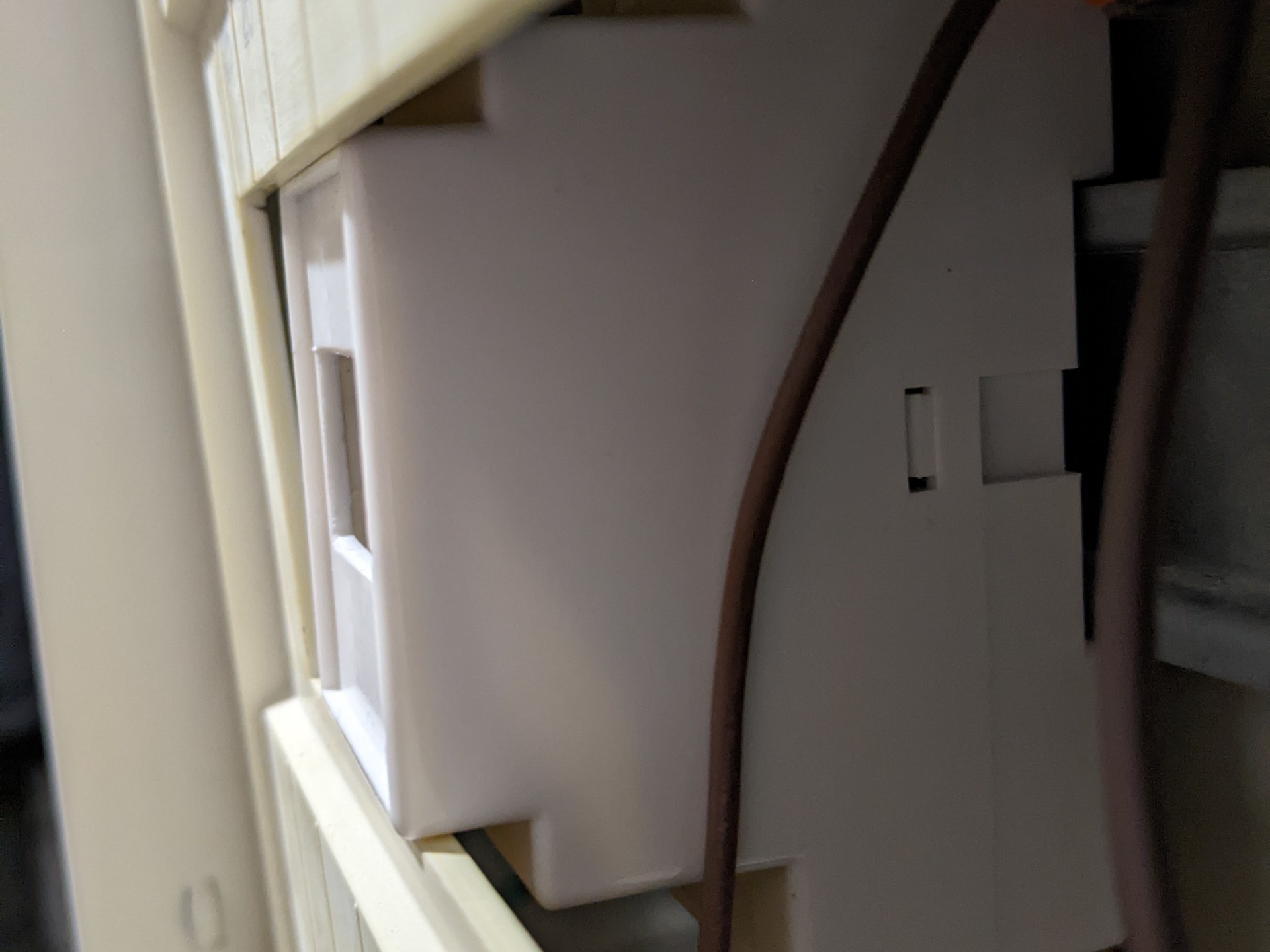
A fun part here. The DIN rail housing is a bit non-standard, so it was impossible to feet it properly in the electric shield. Luckily, this can be fixed with a bit of sanding.
![]()
![]()
One more thing was planned but forgotten in the process – adding a button or photoresistor, so the screen can be turned off:
- after some period (in the case of using a button)
- when there is on light (in the case of using a photoresistor)
It would significantly prolong the life of the OLED screen.
The next log will be about software, as it is ready to some degree.
Power Monitoring
A device based on PZEM-004T that monitors power, current, voltage, frequency, etc.