-
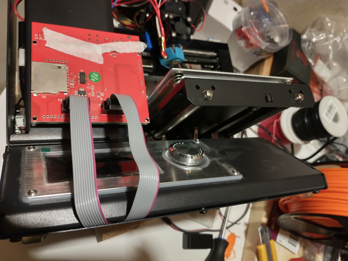
1Replace the stock mainboard with the RAMPS/Mega boards
https://www.instructables.com/Replace-Monoprice-Select-Mini-Controller-With-Ardu/
Ensure that the LCD display cables come out of the bottom of the housing, at the front of the case.
![]()
-
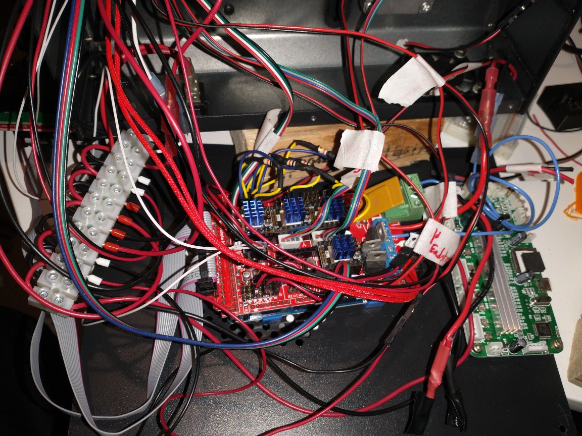
2Set up the RAMPS board for UART with the TMC2208 stepper drivers
https://www.instructables.com/UART-This-Serial-Control-of-Stepper-Motors-With-th/
See the yellow and blue wires and the 1k resistors below
![]()
-
3Replace the hotend
Use the same mounting hardware as the 1.75mm hotend
-
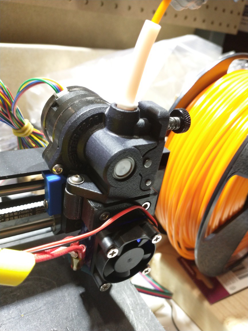
4Attach the Orbiter Extruder
Use 2x M3x20 screws (button or socket head). Washers are recommended, but not required.
![]()
-
5Make an extension cable for the orbiter extruder motor
Ensure that the male end is accessible from the top of the printer, to allow the extruder motor to be swapped out easily
-
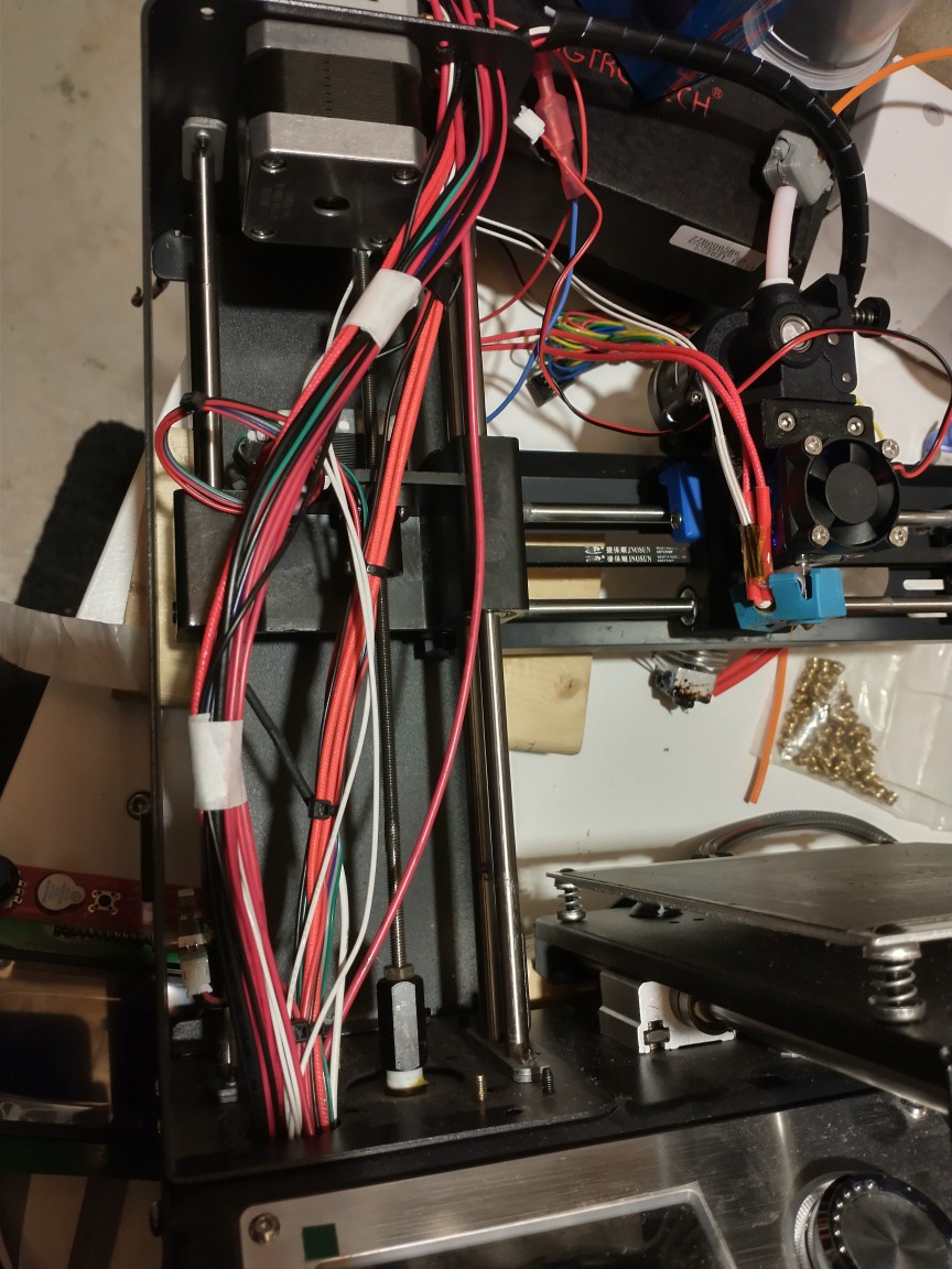
6Remove the front of the Z-axis tower to route the printhead and extruder cables.
Zip tie the cables (not pictured) to prevent interference with the Z-axis movement
![]()
-
7Re-attach the Z-axis tower front cover
-
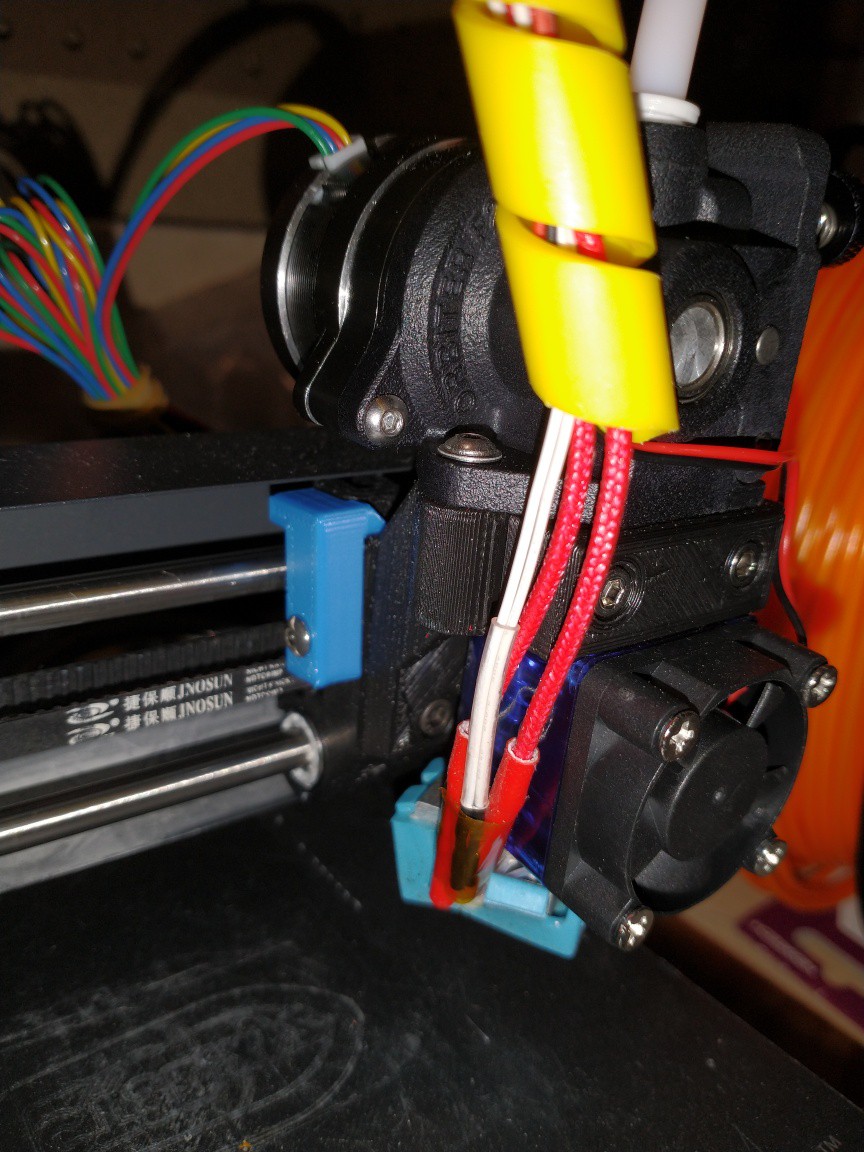
8Print an offset spacer for the X-carriage
Secure using 1x M3x10mm screw (button or socket head). This will ensure that the extruder will not contact the Z-axis tower before the X-axis endstop is triggered. See the blue part pictured below.
![]()
-
9Print the LCD panel mount
-
10Secure the LCD panel to the mount
Use 4x M3x10 screws threaded directly into the plastic. Button head or socket head are suitable
MPSM V2 Direct Drive for 2.85/3.00mm Filament
These modifications will allow this printer to use a direct drive extruder, and print using 2.85mm/3.00mm filament
Discussions
Become a Hackaday.io Member
Create an account to leave a comment. Already have an account? Log In.