 Jesse Farrell
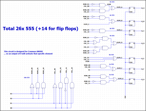
This block takes in 4 bits representing a single digit of the 7-segment display and maps them to a 7-bit output representing digits 0-9. There are two approaches I could take to design this circuit (or atleast two that come to mind). Either I could (a) find the Boolean logic related to each element and create a network of gates that will decode the value on the fly, or I will (b) implement the logic as a MUX. After a bit of tinkering I found that the "Boolean" approach was far more efficient.
Using some Karnough maps, I created the final design can be seen below. Note that I will be using a common anode 7-segment, so to turn on a segment, the output should be 0.
Here are the maps I used for each element. I'm a little rusty on gate simplification so there may be some redundency hidden here.
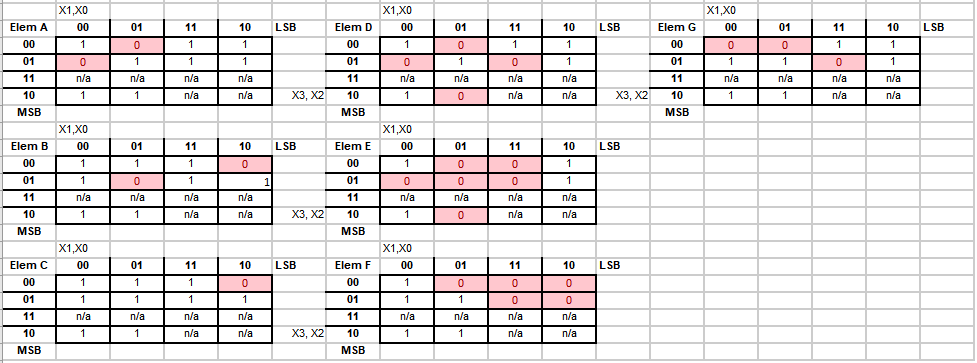
NOTE: there was incorrect logic for elelement B, this was discovered during validation (0010) is not a case where B is off
Discussions
Become a Hackaday.io Member
Create an account to leave a comment. Already have an account? Log In.
You can find a decoding network in the datasheet for the SN7447, a TTL 7-segment LED driver from way back. It may not be as minimal as your network because they could afford to use as many emitters as they needed for the gates, this being TTL.
Are you sure? yes | no
Thanks for the heads up, I thought the schematic probably existed somewhere but I was too determined to do it my own way as a learning exercise ( and to refresh my Karnaugh map knowledge)… that being said I probably should have checked other designs once I finished
Are you sure? yes | no