danjovic
-
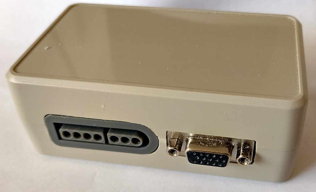
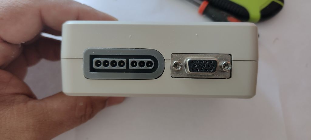
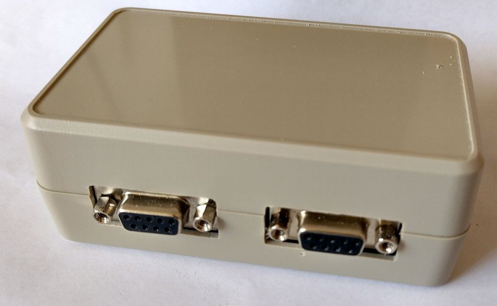
In the box
04/21/2022 at 14:35 • 0 commentsCut the box to fit the board. It demanded a lot of handiwork, which is ok for a diy project, but may render a serialization inviable. In that case two options should b considered
- Machine a COTS box on a CNC.
- Custom 3D print (that nowadays can be ordered online)
![]()
![]()
![]()
![]()
-
Changing the Mode LED
04/12/2022 at 00:14 • 0 commentsNot satisfied with the brightness of the bicolour LED I have lowered the values of the resistors but unfortunately the load was too high for the pin 13 (clock of the HC596) because this pin have already an LED internally.
I have used a neopixel on the pin DATA but it did not worked well because the colour of the neopixel kept changing with the normal data flux (to the HC595). I did nod expected that because the timing is completely different from what the neopixel expects.
I have used then the only remaining pin - TX that so far I have saved for debugging. The solution was to use the #ifdef and #ifundef directives to select either print the debug data on the serial terminal or drive the neopixel
#define _LED 1
// #define DEBUG // uncomment this line to debug on serial
#ifndef DEBUG
Adafruit_NeoPixel pixels(1, _LED, NEO_GRB + NEO_KHZ800);
#endif
...
#ifdef DEBUG
  Serial.begin(9600);
  Serial.println("Debug");
#endif
...
I have updated the schematics and the PCB to include the changes.
![]()
![]()
Video showing the mode change
-
Controller priority
04/09/2022 at 18:55 • 0 commentsAs the standard jaguar controller can not be differentiated from an open circuit, the SNES controller has precedence. In other words the controller operation is mutually exclusive and the SNES controller has a higher priority on the control of the ouputs.
void sampleAndProcessControllerData(void) {

  // clear reports
  atariKeypad[0] = 0xff;
  atariKeypad[1] = 0xff;
  atariKeypad[2] = 0xff;
  atariKeypad[3] = 0xff;

  sampleJaguarController();
  if ( sampleSNESController() )
    processSnesSampleData();
  else
    processJaguarSampledData();
}
New firmware was uploaded to github. -
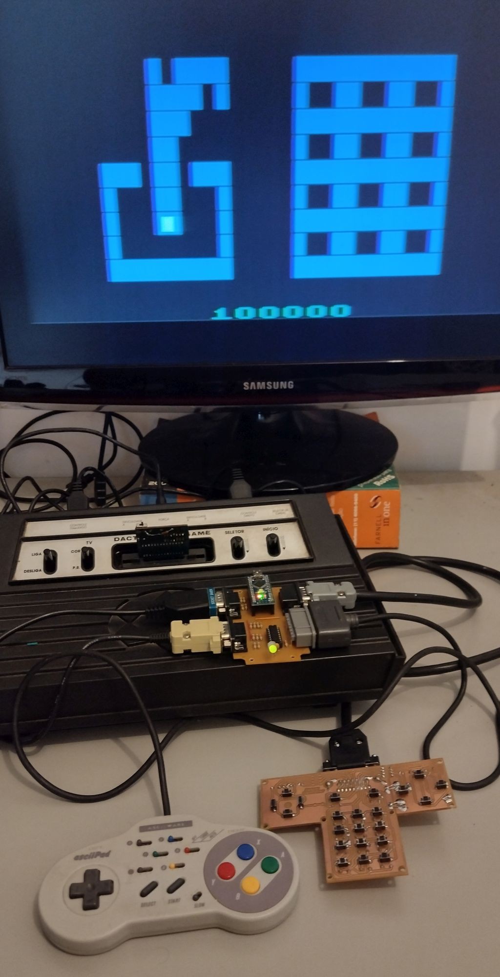
Beta: Jaguar controller working
04/09/2022 at 18:09 • 0 commentsVideo of the interface with the home-built Jaguar controller. On the video I have swapped the sides of the joystick and keyboard because of the low contrast of the red square missile used to mark the keys.
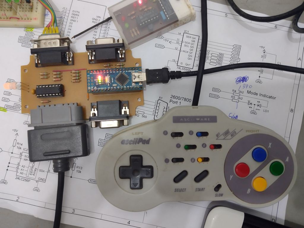
My setup:
![]()
-
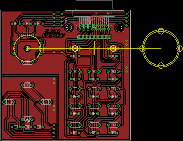
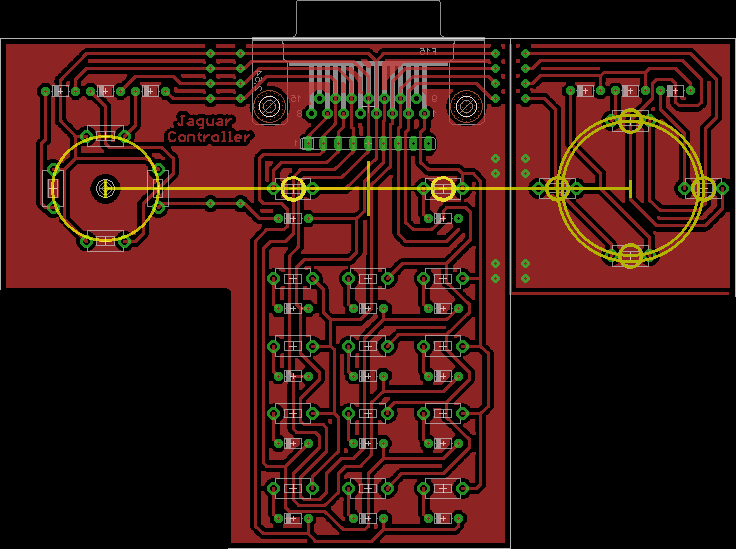
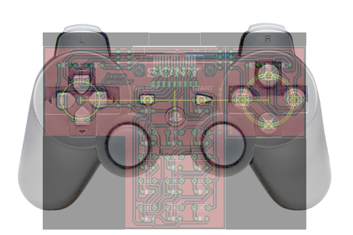
Jaguar controller wannabe
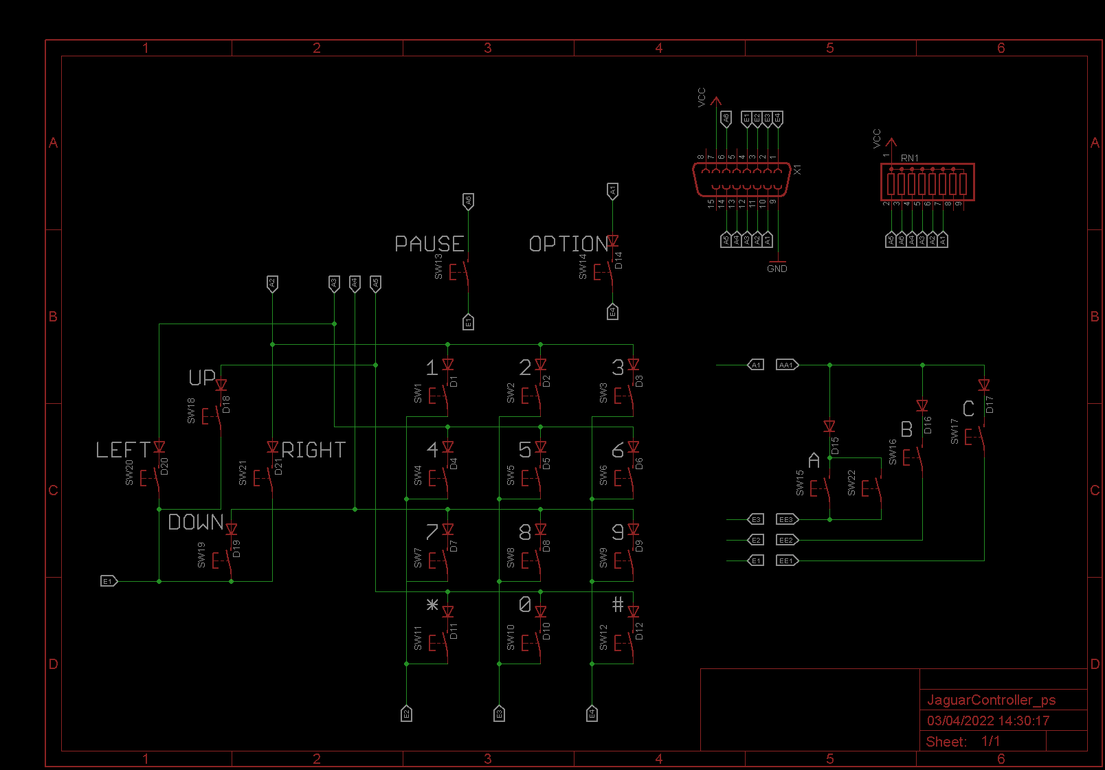
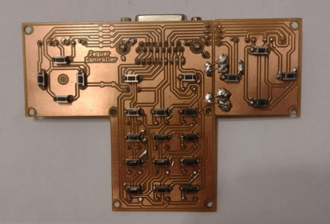
04/03/2022 at 09:39 • 0 commentsI have designed a Jaguar controller board using tactile switches. The directional, action, option and pause buttons were placed so the board could fit under the upper cover of the body of a broken ps/2 controller.
To get around the limitation of Eagle (100mm wide) the left side of the PCB with the action buttons were rotated and translated to the right side of the board.
The assembled version should form a T shape. there are some vias to connect the boards and also to provide mechanical stability
The PCB is single sided, and uses only the top layer, where the tactile switches should be mounted. the other components, diodes, resistor network and DB-15 connector should be mounted on the bottom layer.
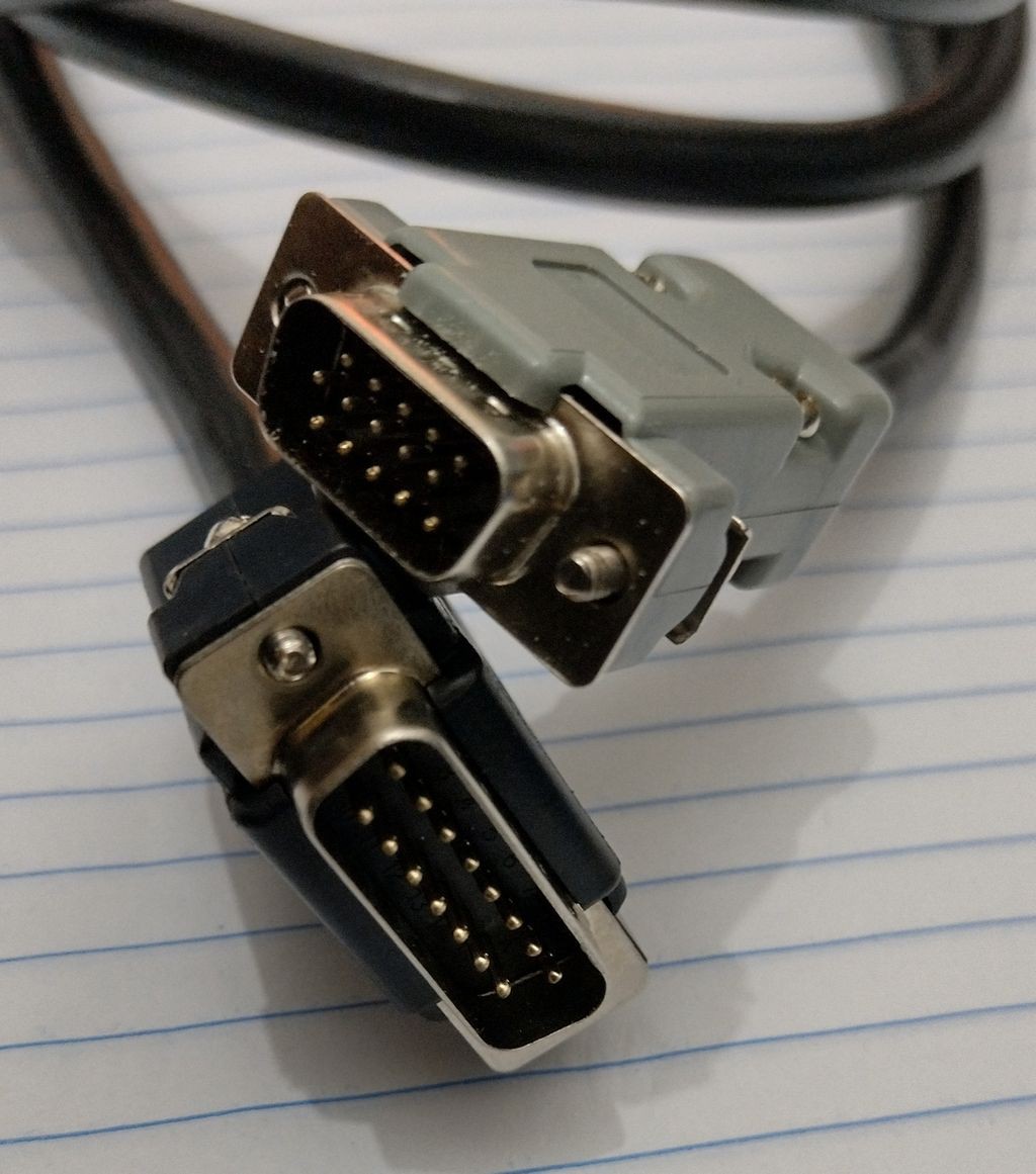
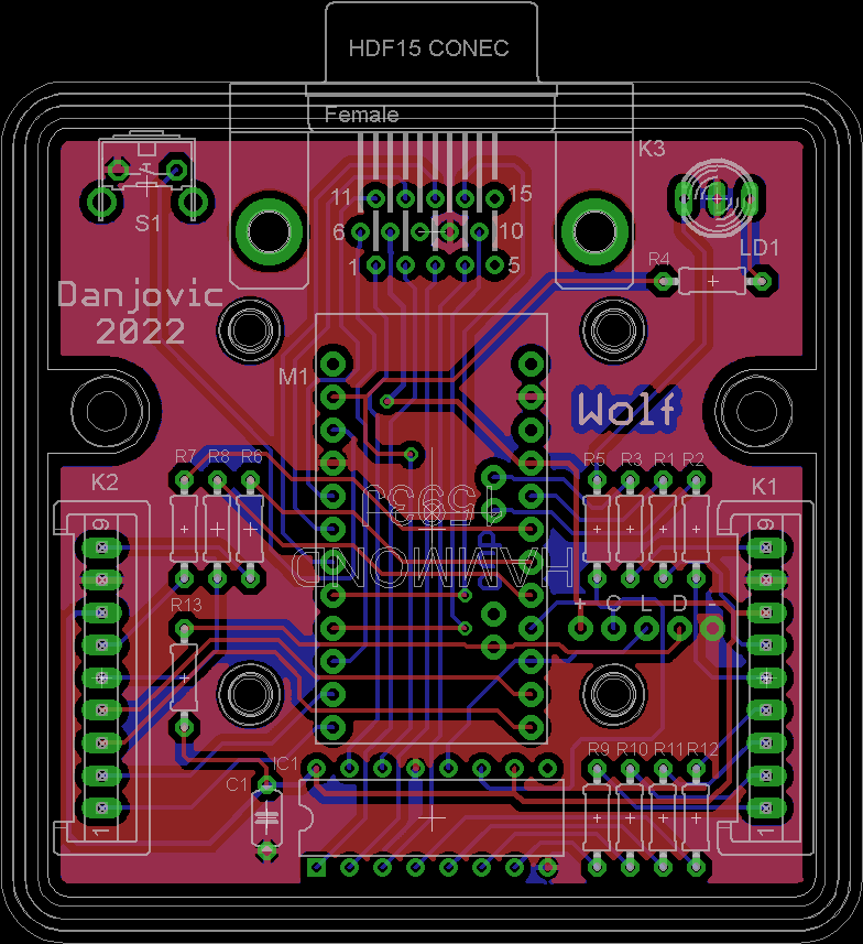
I made a DB-15 to HD15 cable to connect this controller to the Wolf board.
![]()
Schematic diagram![]()
After assembly I realized that I should have designed the board with the buttons on the component size.
![]()
-
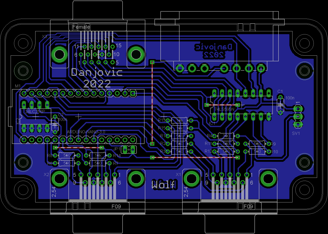
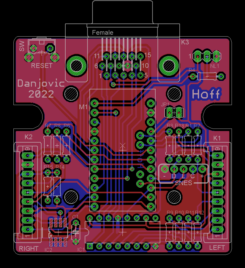
The Wolf and his Cub
03/28/2022 at 00:56 • 0 commentsDespite being possible to use off the shelf components to make DIY reproduction easy, I am not satisfied with the design.
Then I worked on a shorter version of the board that uses the DB-9 replacement cord directly soldered to the board. Same goes for the SNES connector, that should be make of a severed extension cord.
This alternative design fits into a Hammond 1593J box, that is cheaper and smaller.
-
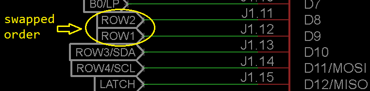
Making the keyboard emulation work
03/28/2022 at 00:23 • 0 commentsAnother debugging session, this time to make the keyboard emulation work. Found a software bug, a pin swapping and a short circuit.
## The software bug was an incorrect logic operation. I wanted to isolate the column bits and used the 'and' operation instead of the 'or'. That caused all the COL pins to get grounded, being interpreted like all keys being pressed at the same time
## The pin swap was causing the keys 123 being swapped with the keys 345. I have swapped the order of the rows 1 and 2.This one was fixed by software, just swapping the constants on the switch() inside the interrupt routine.
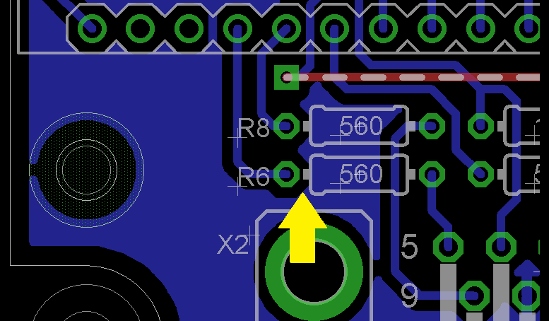
## The last one was causing the first row of keys ( 1 4 7 * ) to never be actuated. I first checked all the code and macros and nothing seemed to be causing such behaviour. Then I disconnected the circuit board from the videogame and shortcircuited the pins 5 and 4 to check the wiring was ok. Then I measured the continuity from Arduino pin A0 to the resistor R6 and it was ok. Finally I have measured the continuity from pin A0 to GND and found a short circuit close to the left pad of R6And here is the keyboard emulation working
-
Debugging
03/20/2022 at 22:58 • 0 commentsStarted to debug the code. So far the SNES controller reading is fine, operating mode selection is fine, Left port driving is fine.
![]()
For this project I have used variables to store the state of the input controls and for the output data to interface with the videogame, thus isolating the sampling functions from the logic funcions and from the driving functions. That makes the code development way more easier than some of my previous projects.
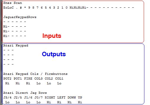
/// Input reports

unsigned long  snesScan;
// bit     31 30 29 28 27 26 25 24 23 22 21 20 19 18 17 16 15 14 13 12 11 10 09 08 07 06 05 04 03 02 01 00
// Gamepad Lo Lo Lo Lo Lo Lo Lo Lo Lo Lo Lo Lo Lo Lo Lo Lo Hi Hi Hi Hi  R  L  X  A RG LF DW UP St Sl  Y  B
// NTT-pad Ec Hi  C  .  #  *  9  8  7  6  5  4  3  2  1  0 Hi Hi Lo Hi  R  L  X  A RG LF DW UP Nx Pr  Y  B

volatile uint8_t jaguarKeypadRow[4] = {255, 255, 255, 255};
//   row   /   bit   7   6   5   4   3   2   1   0
//    0              Hi  Hi  Ps  A   U   D   L   R
//    1              Hi  Hi  C1  B   *   7   4   1
//    2              Hi  Hi  C2  C   0   8   5   2
//    3              Hi  Hi  C3  Op  #   9   6   3

/// Output reports

volatile uint8_t atariKeypad[4]     = {255, 255, 255, 255};
//   row   /   bit   7   6   5   4   3   2   1   0
//    0              Hi  Hi  Hi  Hi  Hi  3   2   1
//    1              Hi  Hi  Hi  Hi  Hi  6   5   4
//    2              Hi  Hi  Hi  Hi  Hi  9   8   7
//    3              Hi  Hi  Hi  Hi  Hi  #   0   *

//   7    6    5    4    3    2    1    0
//   0    0   POT2 POT1 FIRE COL3 COL2 COL1
volatile uint8_t atariKeypadColsFirebuttons;

//   7    6    5    4     3    2    1    0
//  J3/4 J2/5 J1/6 J0/7 RIGHT LEFT DOWN UP
volatile uint8_t atariDirectionalsJaguarRows;
To help me to debug I have also wrote a function that prints the state of such variables whenever they change,
-
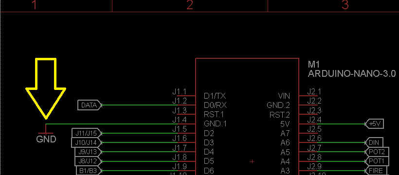
Fixed: Missing GND connection
03/20/2022 at 11:27 • 0 commentsDuring the debug of the code I have found a missing GND connection
It was already fixed and the updated schematics and PCB were submitted to GitHub
-
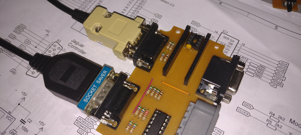
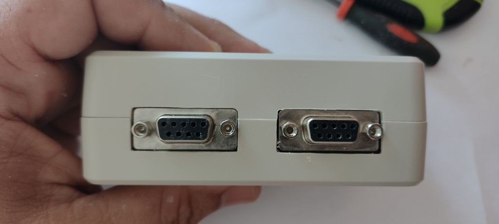
Cables/adapters to the console
03/19/2022 at 06:22 • 0 commentsTwo options for connecting to the console
- Build a cable from a replacement cord and a DB-9 connector
- Use a cable extension plus a "socket saver" adapter
![]()
![]()
Wolf
Use a Jaguar or SNES controller as a joystick and a keypad in Atari 2600 and 7800
 This one was fixed by software, just swapping the constants on the switch() inside the interrupt routine.
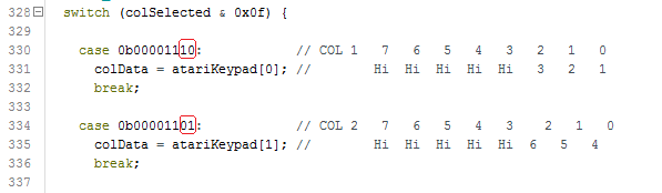
 It was already fixed and the updated schematics and PCB were submitted to GitHub