 SimonXi
After 2 weeks, the PCB finally has arrived at my place, and this is how it looks in its complete form,
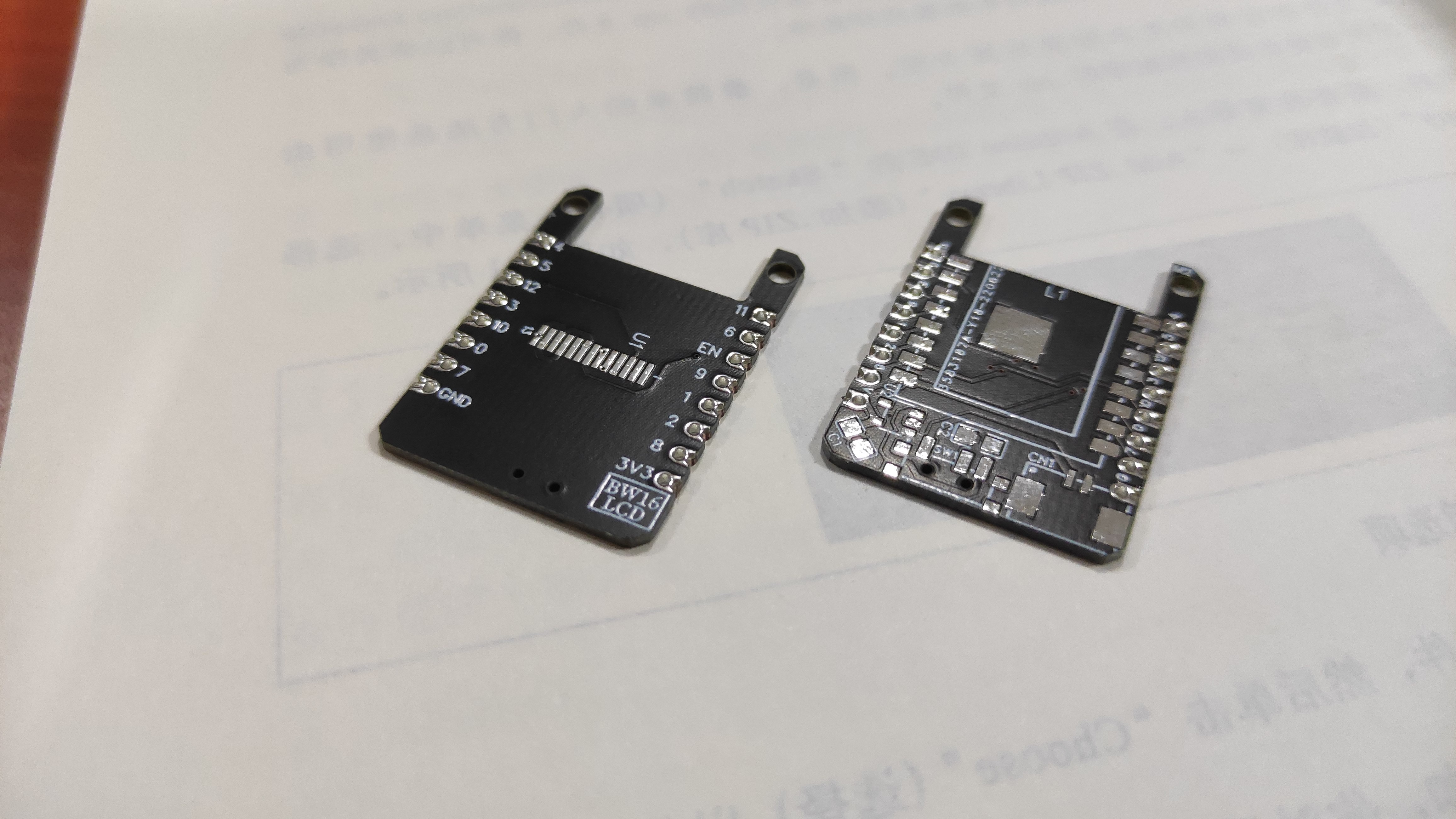
front and back (before soldering)
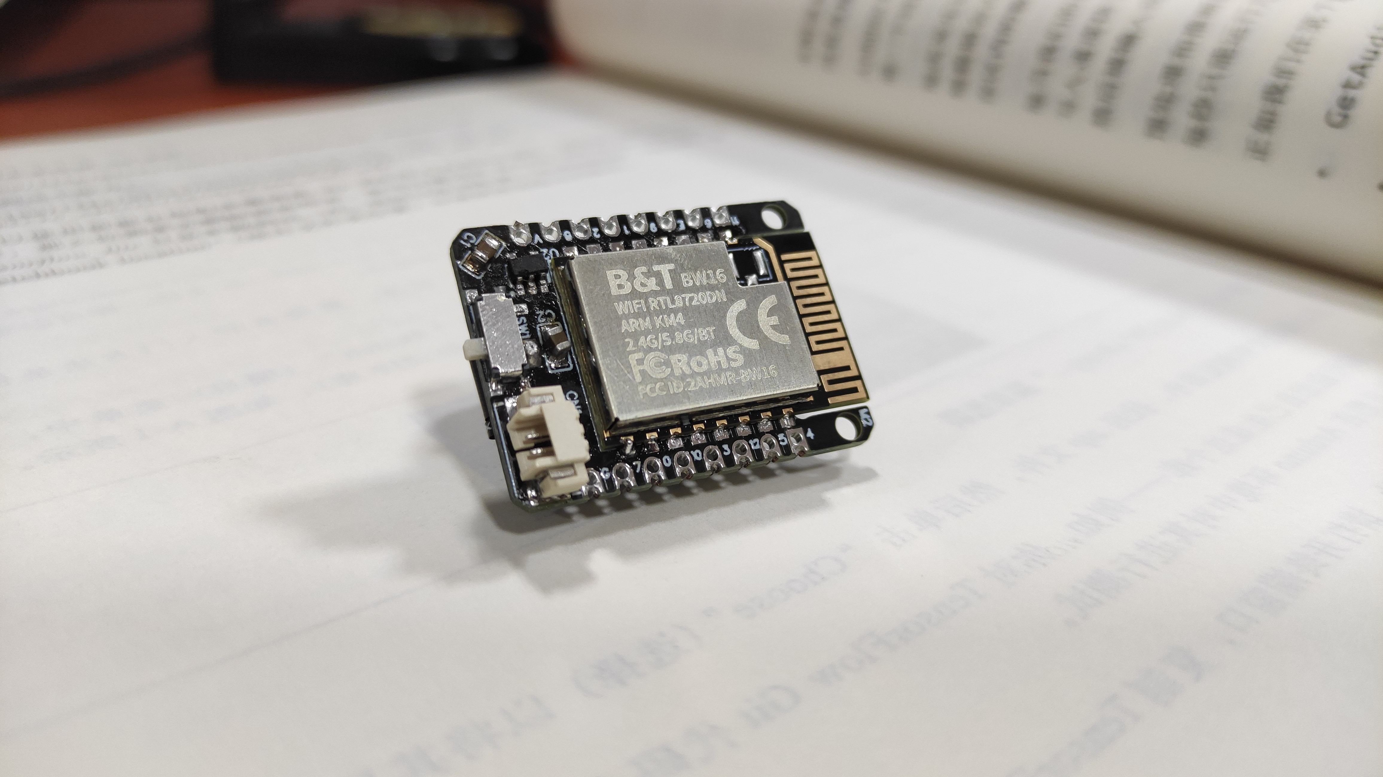
Front view
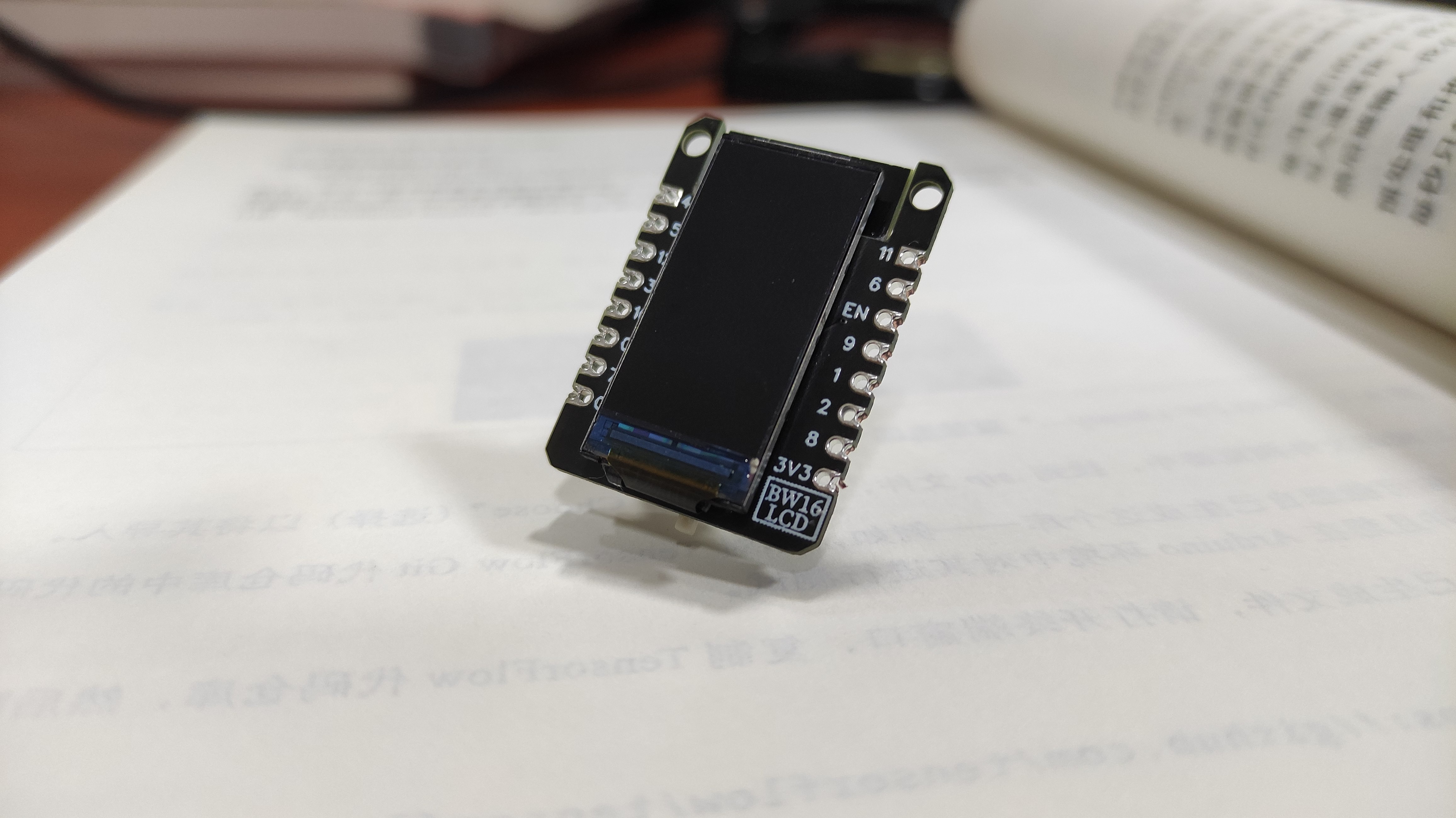
Back view
As you can see, it looks quite nice with the screen attached. However, I got the screen FPC connector pitch wrong and now it only works without the display T _ T
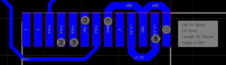
The width here is supposed to be 9mm wide, but it's 10.1mm now. This has taught me an important lesson -- when designing with 3rd party library/symbols, always check the dimension before use!!
For now I can use isolated copper wire to make the connections, but it will be a mess as compare to soldering onto the PCB.
Anyway, I will test with this version first, then fix the issues found and get a new version out, hopefully this time it will take less time~
Discussions
Become a Hackaday.io Member
Create an account to leave a comment. Already have an account? Log In.